Burator. PCB Drilling Machine
Hello! This resource has a lot of people who are engaged in electronics and independently produce printed circuit boards. And each of them will say that drilling PCBs is a pain. Small holes have to be drilled by the hundreds, and each solves this problem for itself.
In this article I want to bring to your attention an open project of a drilling machine that everyone can assemble himself and he will not need to look for CD drives or object tables for the microscope for this.
The design is based on a fairly powerful 12 volt motor from China. Included with the engine, they sell another cartridge, a key and a dozen drill bits of different diameters. Most radio amateurs simply buy these engines and drill boards while holding the tool in their hands.
I decided to go further and, on its basis, make a full-fledged machine for similar engines with open drawings for independent production.

For the linear movement of the engine, I decided to use polished shafts with a diameter of 8mm and linear bearings. This makes it possible to minimize the backlash in the most crucial place. These shafts can be found in old printers or buy. Linear bearings are also widely distributed and available as they are used in 3D printers.
The main frame is made of plywood 5mm thick. I chose plywood because it is very cheap. Both the material and the cutting itself. On the other hand, nothing prevents (if it is possible) to simply cut all the same parts out of steel or plexiglass. Some small parts of complex shape are printed on a 3D printer.
To raise the engine to its original position used two ordinary stationery gum. In the upper position, the engine itself is turned off using a microswitch.
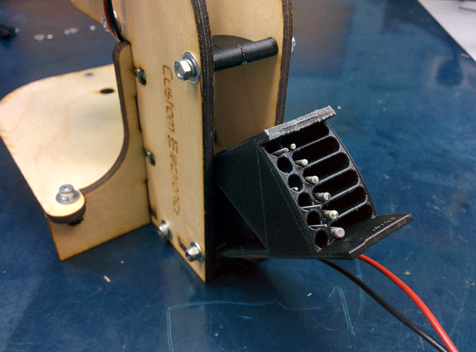
On the reverse side, I provided a place for hreneniyu key and a small pencil case for drills. The grooves in it have different depths, which makes it convenient to store drill bits with different diameters.
But all this is easier to see once on video:
It has a slight inaccuracy. At that moment I got a defective engine. In fact, from 12V they consume at a idle rate 0.2-0.3A, and not two, as stated in the video.
The whole process is shown in detail in the video:
If you follow just such a sequence of actions, then it will be very easy to assemble the machine.
This is how a complete set of all components for assembly looks like this.
In addition to them, the assembly will require a simple hand tool. Screwdrivers, hex keys, pliers, nippers, etc.
Before starting to assemble the machine it is desirable to process the printed parts. Remove possible overflows, supports, and also go through all the holes with a drill of the appropriate diameter. Plywood parts along the cut line may stain with fumes. They can also be treated with sandpaper.
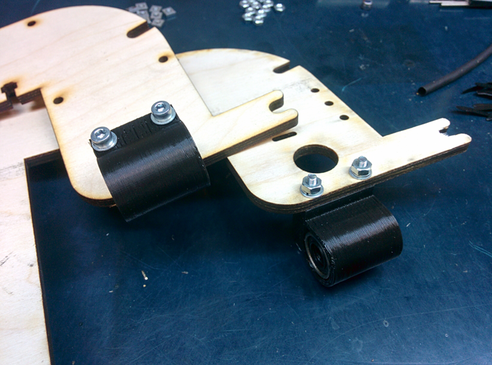
Once all parts are prepared, it is easier to start by installing linear bearings. They slip into the printed parts and are screwed to the side walls:
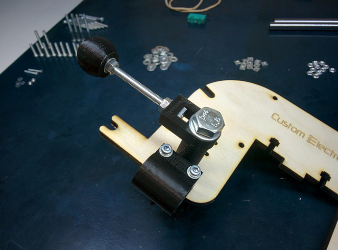
Next, set the handle with gear. The shaft is inserted into a large hole, the base of the handle is installed on it and all this is tightened with a bolt of 8 mm. The handle itself is the screw on the M4:
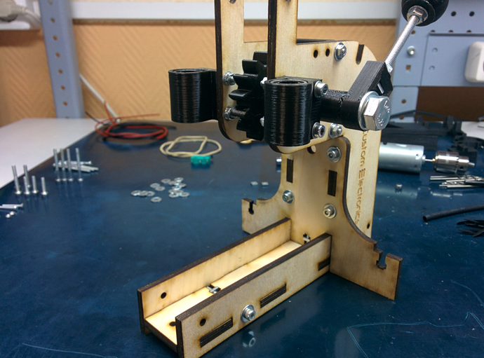
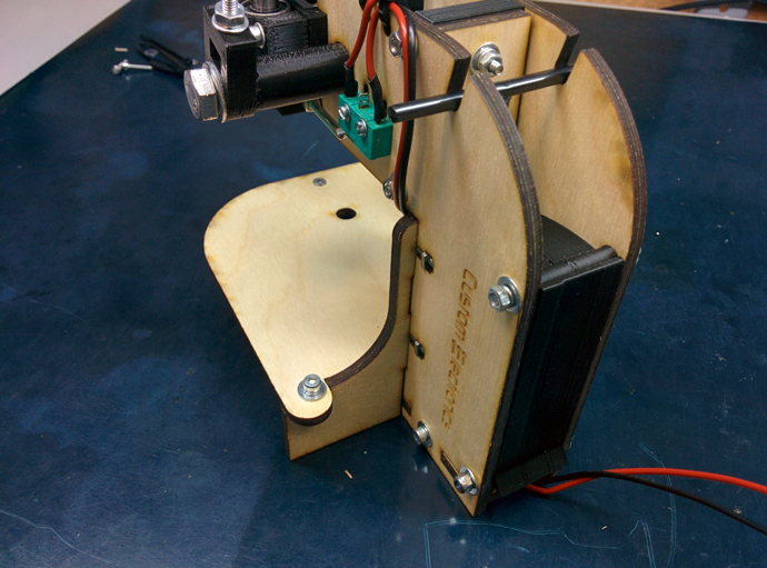
Now you can assemble a plywood base. First, the side walls are mounted on the base, and then a vertical wall is inserted. There is also an additional printed part at the top, which sets the width at the top. Do not apply too much force when tightening the screws in the plywood.

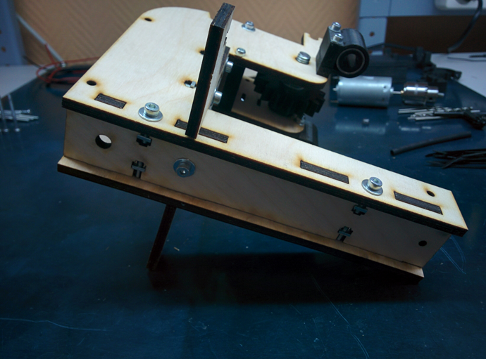
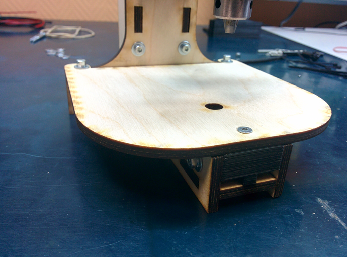
In the table in the front hole, you need to make a countersink, so that the screw with the head soaked does not interfere with drilling the board. A printed fastener is also installed at the end.
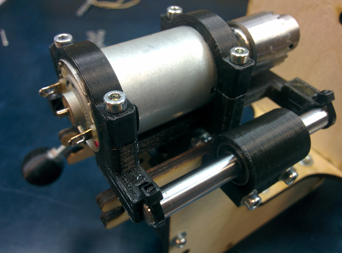
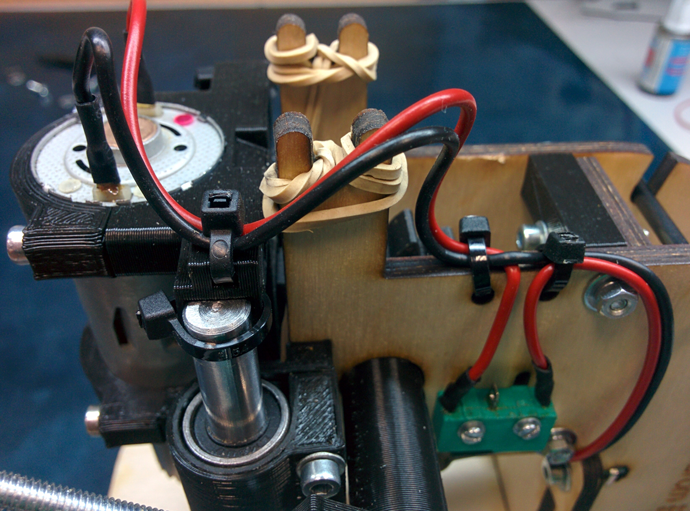
Now you can proceed to the assembly of the engine block. It is pressed with two parts and four screws to the movable base. When installing it, care must be taken that the ventilation holes remain open. On the basis of it is fixed with clamps. First, the shaft is inserted into the bearing, and then the clips snap onto it. Also install the screw M3x35, which in the future will press the microswitch.
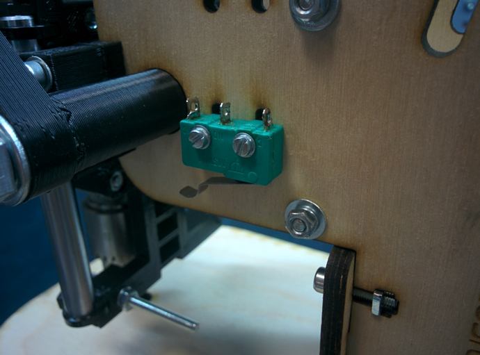
The microswitch is installed on the slot with a button in the direction of the engine. Later his position can be calibrated.
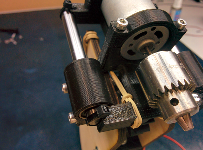
Elastic bands are thrown over the bottom of the engine and threaded through to the "horns." Their tension must be adjusted so that the engine rises to the very end.
Now you can solder all the wires. On the engine block and near the microswitch there are holes for the clamps to secure the wire. Also, this wire can be held inside the machine and withdraw from the reverse side. Make sure you solder the wires on the microswitch to the normally closed contacts.
It remains only to put a pencil case. The top cover must be clamped tightly, and the bottom screw very loosely, using a nut with a nylon insert.
At this assembly is over!
Other people who have already collected such a machine have made many suggestions. If I may, I will list the main ones, leaving them in the author’s form:
All files are collected in the main article about the project on my site . There you can download everything by direct links without registration and other problems.
In this article I want to bring to your attention an open project of a drilling machine that everyone can assemble himself and he will not need to look for CD drives or object tables for the microscope for this.
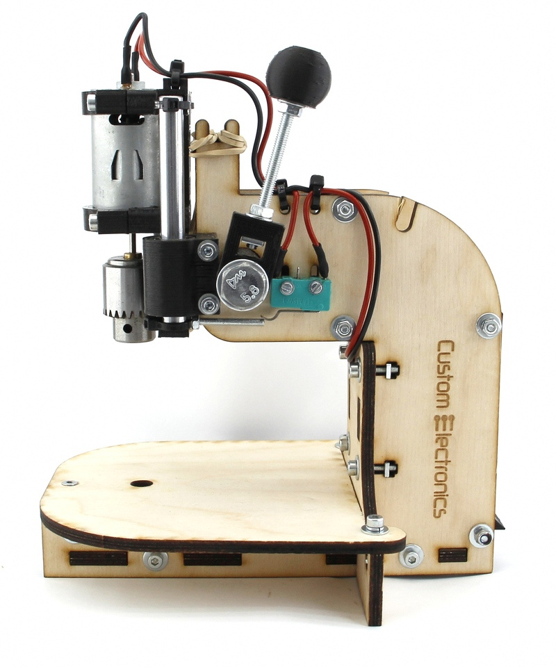
Description of construction
The design is based on a fairly powerful 12 volt motor from China. Included with the engine, they sell another cartridge, a key and a dozen drill bits of different diameters. Most radio amateurs simply buy these engines and drill boards while holding the tool in their hands.
I decided to go further and, on its basis, make a full-fledged machine for similar engines with open drawings for independent production.
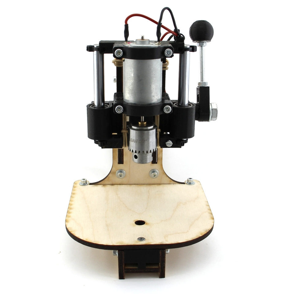
For the linear movement of the engine, I decided to use polished shafts with a diameter of 8mm and linear bearings. This makes it possible to minimize the backlash in the most crucial place. These shafts can be found in old printers or buy. Linear bearings are also widely distributed and available as they are used in 3D printers.
The main frame is made of plywood 5mm thick. I chose plywood because it is very cheap. Both the material and the cutting itself. On the other hand, nothing prevents (if it is possible) to simply cut all the same parts out of steel or plexiglass. Some small parts of complex shape are printed on a 3D printer.
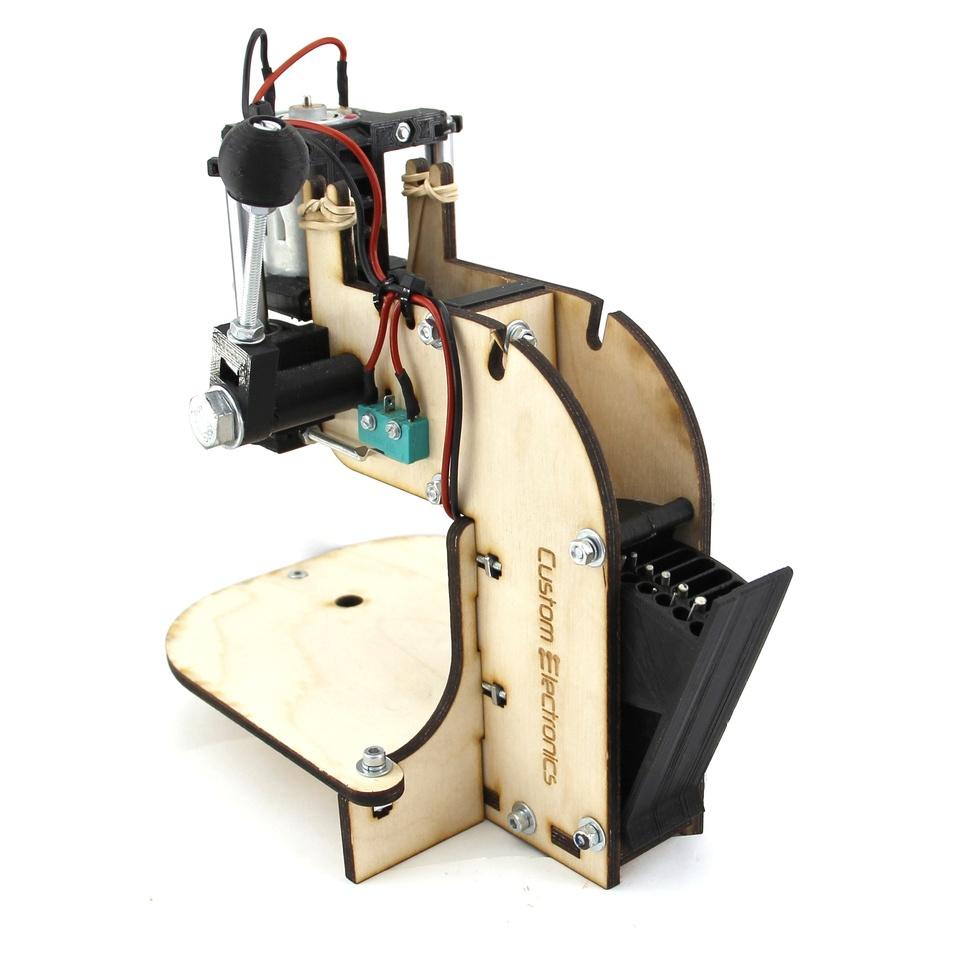
To raise the engine to its original position used two ordinary stationery gum. In the upper position, the engine itself is turned off using a microswitch.
On the reverse side, I provided a place for hreneniyu key and a small pencil case for drills. The grooves in it have different depths, which makes it convenient to store drill bits with different diameters.
But all this is easier to see once on video:
It has a slight inaccuracy. At that moment I got a defective engine. In fact, from 12V they consume at a idle rate 0.2-0.3A, and not two, as stated in the video.
Parts for assembly
- Engine with chuck and collet . On the one hand, the cam cartridge is very convenient, but on the other hand, it is much more massive than the collet clamp, that is, it is often subject to beats and very often they have to be further balanced.
- Plywood parts. A link to laser cutting files in dwg format (prepared in NanoCAD) can be downloaded at the end of the article. It is enough just to find a company that is engaged in laser cutting of materials and transfer the downloaded file to them. I note separately that the thickness of the plywood may vary from case to case. I come across sheets that are slightly thinner than 5mm, so I made 4.8mm slots.
- Details printed on a 3D printer. A link to files for printing details in the stl-format can also be found at the end of the article.
- Polished shafts with a diameter of 8mm and a length of 75mm - 2pcs. Here is a link to the seller with the lowest price for 1m, which I saw
- Linear bearings for 8mm LM8UU - 2pcs
- KMSW-14 microswitch
- Screw M2x16 - 2pcs
- M3x40 screw in / sh - 5pcs
- Screw M3x35 slot - 1pc
- M3x30 screw in / sh - 8pcs
- Screw M3x30 high / w with a head soak - 1pc
- Screw M3x20 high / low - 2pcs
- Screw M3x14 in / sh - 11pcs
- Screw M4x60 slot - 1pc
- Bolt M8x80 - 1 pc
- Nut M2 - 2pcs
- Square M3 Nut - 11pcs
- Nut M3 - 13pcs
- M3 nut with nylon ring - 1pc
- M4 nut - 2pcs
- Nut M4 square - 1 pc
- M8 nut - 1pc
- M2 washer - 4pcs
- M3 washer - 10pcs
- M3 washer increased - 26 pieces
- M3 horizontal washer - 17pcs
- M4 washer - 2pcs
- M8 washer - 2pcs
- Washer M8 washer - 1pc
- Assembly wire set
- Set of heat shrink tubing
- Clamps 2.5 x 50mm - 6pcs
Assembly
The whole process is shown in detail in the video:
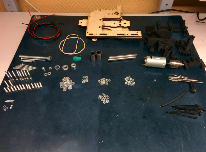
If you follow just such a sequence of actions, then it will be very easy to assemble the machine.
This is how a complete set of all components for assembly looks like this.
In addition to them, the assembly will require a simple hand tool. Screwdrivers, hex keys, pliers, nippers, etc.
Before starting to assemble the machine it is desirable to process the printed parts. Remove possible overflows, supports, and also go through all the holes with a drill of the appropriate diameter. Plywood parts along the cut line may stain with fumes. They can also be treated with sandpaper.
Once all parts are prepared, it is easier to start by installing linear bearings. They slip into the printed parts and are screwed to the side walls:
Next, set the handle with gear. The shaft is inserted into a large hole, the base of the handle is installed on it and all this is tightened with a bolt of 8 mm. The handle itself is the screw on the M4:
Now you can assemble a plywood base. First, the side walls are mounted on the base, and then a vertical wall is inserted. There is also an additional printed part at the top, which sets the width at the top. Do not apply too much force when tightening the screws in the plywood.
In the table in the front hole, you need to make a countersink, so that the screw with the head soaked does not interfere with drilling the board. A printed fastener is also installed at the end.
Now you can proceed to the assembly of the engine block. It is pressed with two parts and four screws to the movable base. When installing it, care must be taken that the ventilation holes remain open. On the basis of it is fixed with clamps. First, the shaft is inserted into the bearing, and then the clips snap onto it. Also install the screw M3x35, which in the future will press the microswitch.
The microswitch is installed on the slot with a button in the direction of the engine. Later his position can be calibrated.
Elastic bands are thrown over the bottom of the engine and threaded through to the "horns." Their tension must be adjusted so that the engine rises to the very end.
Now you can solder all the wires. On the engine block and near the microswitch there are holes for the clamps to secure the wire. Also, this wire can be held inside the machine and withdraw from the reverse side. Make sure you solder the wires on the microswitch to the normally closed contacts.
It remains only to put a pencil case. The top cover must be clamped tightly, and the bottom screw very loosely, using a nut with a nylon insert.
At this assembly is over!
Additions
Other people who have already collected such a machine have made many suggestions. If I may, I will list the main ones, leaving them in the author’s form:
- By the way, those who have never worked with such details before would be well reminded that plastic from 3D printers is afraid of heating. Therefore, you should be careful here - you should not go through the holes in such details with a high-speed drill or Dremel. Pens, pens ....
- I would also recommend installing the microswitch at the very early stage of the assembly, since you need to be able to screw it to the already assembled bed - there is very little free space. It would also be advisable to advise the craftsmen in advance at least to tilt the microswitch contacts (and even better to solder the wires to them in advance and protect the soldering places with shrink tubing sections) so as not to damage the plywood parts during the soldering.
- Apparently I was lucky and the cartridge on the shaft was not centered, which led to a serious vibration and hum of the entire machine. It was possible to fix it by centering with "pliers", but this is not a good option. since the axis of the rotor is bending, and it is no longer realistic to remove the cartridge, there are fears that I will pull out this very axis.
- Tighten screws with washers as follows. Tighten the screw to the moment when the lock washer closes (straightens). After that, turn the screwdriver 90 degrees and stop.
- Many advise to attach to it the speed regulator according to the scheme Savova. It turns the engine slowly when there is no load, and increases the speed when the load appears.
Download links
All files are collected in the main article about the project on my site . There you can download everything by direct links without registration and other problems.
All Articles