We disassemble the magnetic resonance imager
Quantum physics, mathematics, biology, cryogenics, chemistry and electronics are intertwined in a single pattern in order to incarnate in the gland and show the real inner world of a person, and even read his thoughts. The electronics of such devices, in terms of reliability and complexity, can only be compared with space devices. This article is devoted to the equipment and the principles of magnetic resonance imaging.
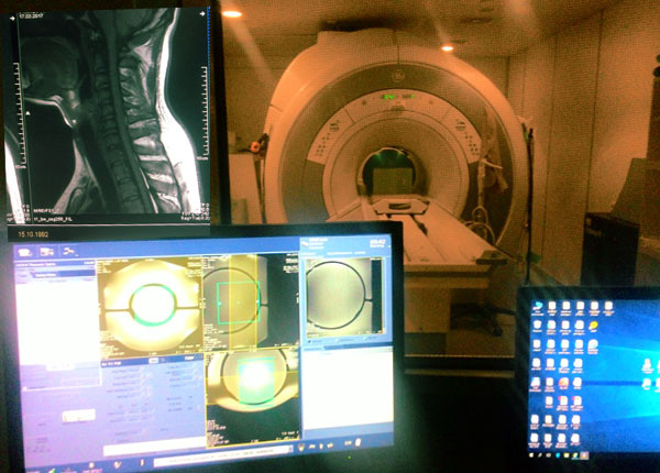
In the field of modern tomography, mastodons of the electronic world are leading: Siemens, General Electric, Philips, Hitachi. Only such large companies can afford the development of such complex equipment, the cost of which usually amounts to tens (almost hundreds) of millions of rubles. Of course, the repair of such expensive equipment from an official representative flies into a huge penny to the owner of the device (and by the way, they are mostly private, and not public). But do not despair! As well as service centers for repairing laptops, telephones, CNC machines, and in fact any electronics, there are firms that repair medical equipment. I work in one of these companies, so I’ll show you interesting electronics and try to describe its functionality in clear words.
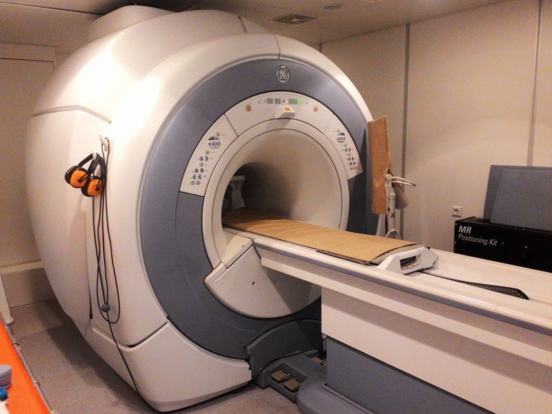
GE Healthcare Magnetic Resonance Imaging with 1.5 Tesla field. The table is detached from the tomograph and can be used as a regular gurney.
All the magic of MRI begins with quantum physics, from which the term "spin" originates, applied to elementary particles. You can find a bunch of definitions of what a spin is, generally accepted - this is the moment of the particle's momentum, whatever that means. In my understanding, particles, as it were, constantly rotate (simplified) while creating disturbances in a magnetic field. Since the elementary particles, in turn, form the nuclei of atoms, it is believed that their spins add together and the nucleus has its own spin. At the same time, if we want to somehow interact with atomic nuclei using a magnetic field, it will be very important for us that the nuclear spin is non-zero. Coincidence or not, but the most common element in our universe - hydrogen has a nucleus in the form of a single proton, which has a spin equal to 1/2.
By the way
Spin can take only certain values, such as integers for example 0,1,2, and half-integers, like 1/2 like that of a proton. For those unfamiliar with quantum physics, this seems unnatural, but at the quantum level, everything is divided into portions, and becomes somewhat discrete.
This means that, simply, hydrogen nuclei can be considered as very small magnets having a north and south pole. And is it worth mentioning that hydrogen atoms in the human body are just a sea (about 10 ^ 27), but since we do not attract glands to ourselves, it becomes obvious that all these small “magnets” are balanced between themselves and the rest of the particles, and the common magnetic body moment is almost zero.
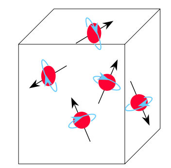
Illustration from Evert Blink's book, The Basics of MRI. Protons with black arrows symbolizing a compass needle rotate in the direction of the blue arrow.
By applying an external magnetic field, it is possible to bring this system out of balance and the protons (not all of course) change their spatial orientation in accordance with the direction of the field lines.
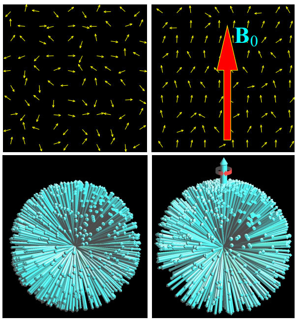
Illustration from the book Lars G. Hanson Introduction to Magnetic Resonance
Imaging Techniques. The proton spins in the human body are shown as arrow vectors. On the left there is a situation when all protons are in magnetic equilibrium. Right - when an external magnetic field is applied. The bottom renderings show the same thing in the three-dimensional version, if you build all the vectors from one point. With all this, there is a rotation (precession) around the magnetic field lines, which is shown by a round red arrow.
Before protons are oriented in accordance with the external field, they will fluctuate (precess) for some time around the equilibrium position, like a compass needle, which would oscillate near the north mark, if the manufacturer had not prudently added a damping liquid inside the dial. It is noteworthy that the frequency of such vibrations varies for different atoms. For example, methods of resonant determination of the composition of the test substance are based on the measurement of this frequency.
By the way
This frequency is not nameless and is named after the Irish physicist Joseph Larmor, which is called the Larmor frequency, respectively. It depends on the magnitude of the applied magnetic field and a special constant - the gyromagnetic ratio, which depends on the type of substance.
For nuclei of hydrogen atoms in a field of 1 Tesla, this frequency is 42.58 MHz, well, or in simple words, the proton oscillations around the force lines of the field of such intensity occur about 42 million times per second. If we irradiate protons with a radio wave with an appropriate frequency, then a resonance will occur, and the oscillations will increase, the vector of total magnetization will shift by a certain degree relative to the lines of the external field.
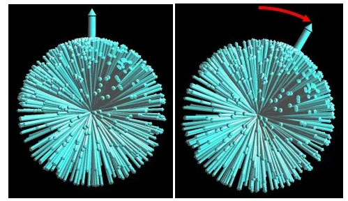
Illustration from the book Lars G. Hanson Introduction to Magnetic Resonance Imaging Techniques. It is shown how the total magnetization vector shifts after exposure to a radio wave with a frequency that causes resonance in the system. Do not forget that all this continues to rotate relative to the magnetic field line of force (in the figure it is located vertically).
Here the most interesting begins - after the interaction of radio waves with protons and the resonant amplification of oscillations, the particles again tend to come to an equilibrium state, while emitting photons (of which a radio wave consists). This is called the effect of nuclear magnetic resonance. In fact, the entire body under study turns into a huge array of miniature radio transmitters, the signal from which you can catch, localize and build a picture of the distribution of hydrogen atoms in a substance. So, as you may have guessed, in fact, an MRI shows a picture of the distribution of water in the body. The stronger the field strength, the greater the number of protons that can be used to receive signals, so the resolution of the scanner is directly dependent on this.
This effect is manifested not only in strong magnetic fields - every day, even on the way to the store for bread, the protons of our body are influenced by the magnetic field of the Earth. Researchers from Slovenia, for example, built an experimental MRI system using only the magnetic field of our planet.
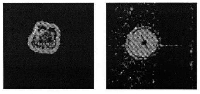
Illustration from the scientific article “Magnetic Resonance Imaging System Based on
Earth's Magnetic Field »Authors: Ales Mohoric, Gorazd Planins, and others. Demonstrates images obtained using an experimental system. On the left is an apple, on the right is an orange. It is indicative not that images with poor quality are obtained, but the very fundamental possibility of using MR in weak fields.
Of course, in commercial medical scanners, the magnetic field strength is many times higher than that of the earth. Scanners with a field of 1, 1.5 and 3 Tesla are most often used, although there are both weaker (0.2, 0.35 Tesla) and harsh monsters in 7 and even 10 tesla. The latter are used mainly for research activities, and in our country, as far as I know, there are none.
Structurally, the field in the scanner can be created in different ways - these are permanent magnets, electromagnets, and superconductors immersed in boiling helium along which large currents flow. The latter are widely distributed, and are of the greatest interest, since they make it possible to achieve incomparably greater field strength compared with other options.
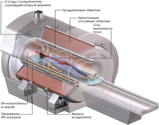
The typical design of the MRI apparatus, the field in which is created by the current flowing through superconductors. Source - the Internet.
The temperature of the superconducting windings is maintained due to the gradual evaporation of the coolant - liquid helium; in addition, a cryocooler works in the system, in the jargon of medical technicians called “cold head”. He publishes the characteristic sounds of champing, which you probably heard if you have ever seen the device at close range. The current in superconductors flows constantly, and not only during the operation of the device, respectively, there is always a magnetic field. On the ignorance of this fact often come across filmmakers (for example, in the last season of the series “Black Mirror” there was a similar blunder).
On the control panel of devices of this type there is a large red button that allows you to turn off the magnetic field (Rundown magnet). It is not without irony called the “Firing Button”.
One of the control panels of the Siemens tomograph
Pressing this button turns on emergency heaters in the refrigerant tank, which raises the temperature of the windings to a critical point, after which the process goes avalanche: after the windings acquire resistance, the current through them instantly heats them and everything around, leading to the release of helium through a special pipe. This process is called “quench”, and this is probably the saddest thing that can happen with the device, since it takes a lot of time and money to restore its working capacity after this.

Siemens Espree tomograph, with a field of 1.5. Tesla, pay attention to the metal keys that lie quietly on the table - there is no more magnetic field here. Was purchased for some public clinics from Siemens. It has a relatively small size of the vessel and a large diameter aperture. It is believed that such a shortening of the construction resulted in the fact that he often likes to let helium into the wind by itself (at least the device in the photo does it with enviable regularity).
In the meantime, after a small digression, let us return to the theory. If you simply take the radio waves emitted by the protons of the body in response to resonant radio pulses, the picture does not come out. How to localize the signal that comes from all parts of the body? At one time, researchers Paul Lauterbur and Peter Mansfield received the Nobel Prize in medicine for solving this problem. In short, their solution consists in applying additional windings in the apparatus, creating an almost linear change in the magnetic field strength along the chosen direction - the field gradient. Since our space seems to be three-dimensional, there are three windings, the X, Y and Z axes.
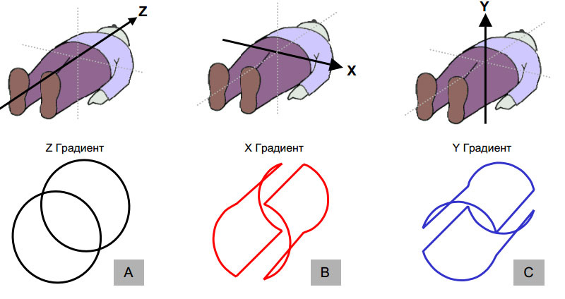
Illustration from Evert Blink's book, The Basics of MRI. This is approximately the way additional gradient windings inside the apparatus look like - real windings of course have a more complex structure.
If the magnetic field strength varies linearly, then when one of the gradients is activated, the protons along this direction will have a different resonant frequency.
Illustration from howequipmentworks.com. Gradient windings (blue) and radio frequency winding (green) are symbolically drawn. It is shown that when creating a field gradient along the table at point A, the resonant frequency of the protons will differ from the frequency at point B
The use of gradients allows you to manipulate the field so that the signal comes only from specific areas. Depending on the amplitude of the received signal, the pixel brightness in the picture is selected. The greater the concentration of protons in the region, the brighter the result.
Of course...
Such a description is of course greatly exaggerated. In reality, the signal is localized by combining all three gradients at once, and the picture is not built pixel by pixel, as you might think from this description, but at once as a whole line. The famous Fourier transform plays a significant role in this. A detailed description can be found in the book “Introduction to Magnetic Resonance Imaging Techniques” by Lars G. Hanson. Alas, this article does not contain everything.
In order to create a magnetic field gradient, a large current must be passed through the gradient windings, and the pulse must be quite short-lived and with a steep front, and for some programs it is required that the current direction in the gradient winding instantly change to the opposite for reversal. Powerful pulse converters are engaged in it, they occupy the whole rack in hardware.
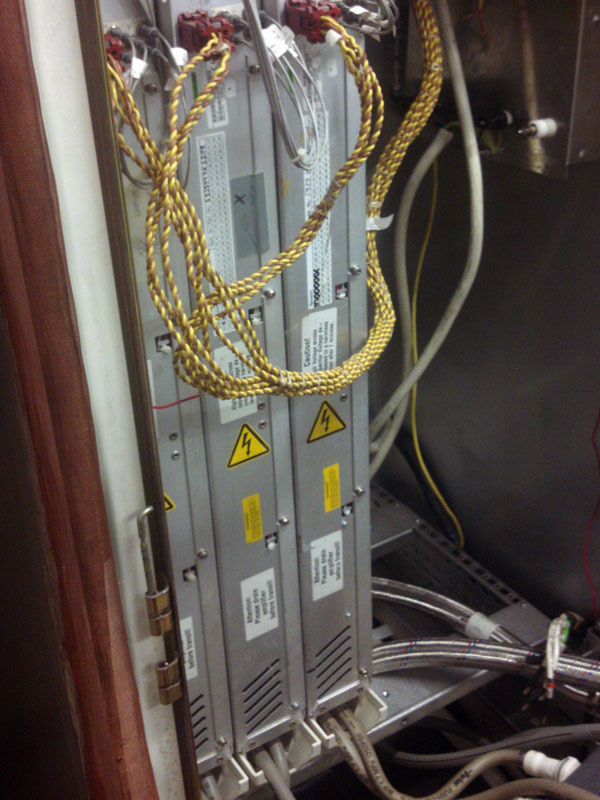
Gradient amplifiers apparatus Siemens Harmony 1T. Performance data - up to 300 Amps and up to 800 Volts, when using six modules - the photo shows three modules.
Siemens devices traditionally use water cooling of power components - the tubes can be seen in the photo. This often results in (interesting pun intended) a good salute for any leak. Despite the vaunted German quality, no one bothered to install leakage sensors (in this regard, they would have to learn from GE). But in fairness, concrete gradient blocks rarely flow, more often they fail for no apparent reason.
The internals of the old-type Siemens Harmony gradient module.
A module like the one shown in the photo is difficult to repair - transistors are glued to the copper tube for something like cold welding, and they burn there in dozens at once. To remove the fee, you need to unsolder several dozen legs at the same time! Better forget this nightmare, and look at a more recent solution from the German manufacturer.
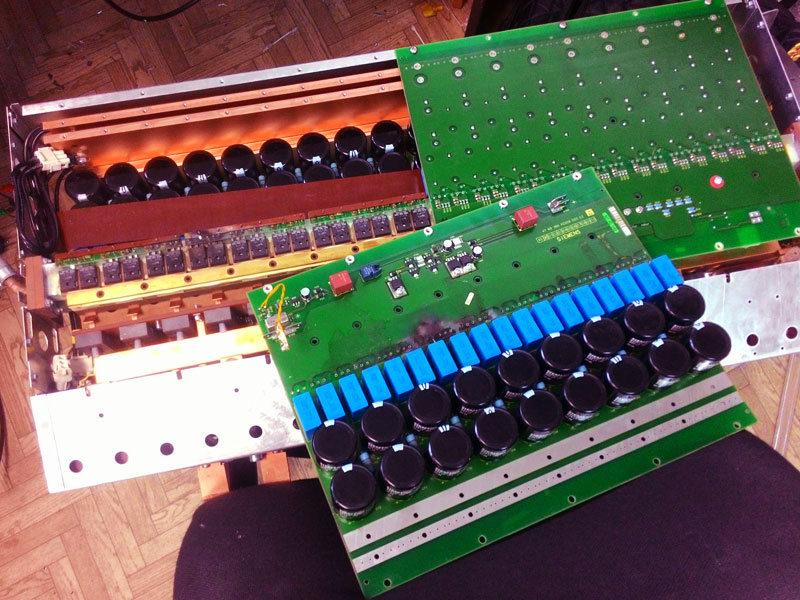
Gradient amplifier from Siemens Harmony. Newer version. Two symmetrical boards are bolted to very powerful field effect transistors. Transistors work in groups of six in parallel, of course they also burn not one by one. The model in the photo is already slightly “split off”, instead of the native connectors between the boards, copper plates are soldered. Pay attention to the upper right corner of the photo - these are optical cables through which there is a signal to open the keys. If you mix up their connection - the unit immediately burns with a loud bang, no protection "from a fool" in this technique is not provided.
One of the main problems in the repair is the lack of any documentation, especially as the equipment is very specialized. Therefore, sometimes you have to fill a lot of cones and burn quite a lot of expensive components to understand what was wrong. Of course, you can buy service manuals for money, but as a rule, they are very superficial. Cool companies keep their secrets secure.
The stronger the magnetic field in the apparatus, the correspondingly more powerful should be the gradient transducers. In devices with a field of 1.5 T and 3 T, a bunch of parallel field-effect transistors that need to be recruited to provide the necessary power becomes too huge, IGBT assemblies, similar to those used in industrial frequency converters for controlling motors, come into play.

Quantum Cascade gradient amplifier in parsing, current up to 500 Amps, output voltage up to 2000 V. It consists of 20 powerful IGBT assemblies. There is an interesting point here - the assembly itself will not withstand 2 kilovolts, this voltage is obtained by using five independent sources of 400V each. My dream is to assemble a Tesla coil from this unit.
What is happening with the gradient windings, when such monstrous currents flow along them, taking into account the fact that they are also in a non-weak magnetic field? The force of Ampere, of course, causes them to deform, but they are firmly filled with resin. Nevertheless, even this does not save - since the gradients work in the range of sound frequencies, the vibrations arising from this can generate quite loud sounds that resemble a hammer with a hammer on a nail (with the proviso that you heard hammering about 5000 beats) per second). Therefore, in almost any MRI device there are headphones or earplugs. Software and hardware constantly monitor the sound level in the scanner room so that decibels do not go beyond the permissible limits. The magnetic field that is changing rapidly with gradients, coupled with radiofrequency pulses generating resonance, induces eddy currents in any metal surface near the scanner, which leads to metal vibration and slight heating, and characteristic artifacts will appear in the photographs even from small metal fillings. It is for this reason that they need to get rid of all the metal (it is not necessary to remove the seals) before an MRI examination.
For the creation of radio frequency pulses of the desired frequency, the synthesizer block is responsible (in Siemens devices) or exciter (in the case of GE devices). Despite the different names, their functions are about the same. These units are generally reliable and rarely need repair if handled with care. The signal is formed by digital-analog synthesis, and is a sinc-function.
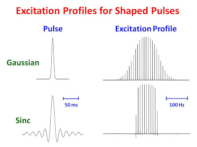
On the left, two types of radiofrequency pulses are demonstrated - Gaussians and sinc, also known as the cardinal sine. The right shows the excitation profile when used as a radio frequency excitation signal — that is, roughly shows the shape of the region where the protons will enter into resonance, side view. Of course, the lower version is more preferable for creating images (slices), especially when they are located close to each other, in order to reduce the effect of signals outside the selected scan area.
Finally, we approached, without exaggeration, the most interesting in my opinion unit in the entire tomograph - a radio-frequency power amplifier, which converts a weak signal from a synthesizer into a powerful one supplied to a transmitting antenna in the device.
By the way
In foreign literature, all antennas related to the tomograph are called “Coil”, in Russian the name “coil” stuck. You are unlikely to ever hear the word “antenna” in relation to an MRI. Body coil - or "body coil" in the local dialect is the main receiving-transmitting antenna of the tomograph, but there are others besides it, but more about them.
The power of the amplifier for a tomograph with a field of 1T is 10 kW, for a field of 1.5T, already 15 kW, respectively, for higher-field devices, more power is needed in terms of radio frequency radiation. This is one of the reasons why high-field apparatuses have not yet become firmly established in clinical practice. But let us be without fanaticism - constantly talking on the mobile phone you will receive more than one session in the MRI machine.
As a rule, this unit combines complex intricate control and protection schemes, radio frequency chips, high voltages, and cooling problems.
In tomographs General Electric and Hitachi put power amplifiers, manufactured by Analogic. They have a beautiful layout of components on the board, high survivability - as a rule, several transistor cascades in their amplifiers work in parallel, and the output adder is designed so that when one amplification stage fails, the unit will continue to work, although not at full capacity.

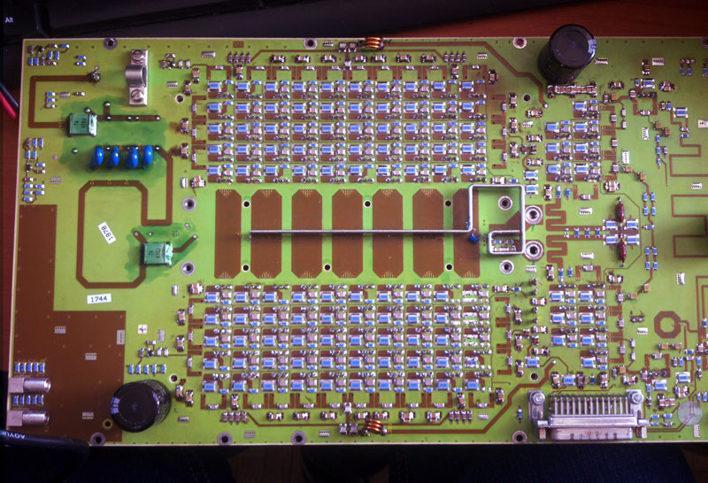
Amplifier board from GE. Beautiful and spectacular design!
Whole block 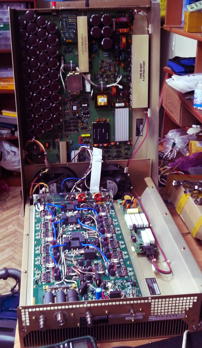
In the device with a field of 1.5T there are two such handsome, 8 kW each. The upper nine-layer (!) Board is a tricky switching power supply, and the amplifier itself is located on the bottom board. He came to us because of the fault of the upper board. In the absence of time for proceedings with the scheme, they successfully hacked and assembled a replacement from two server power supply units. In addition, by selecting steeper transistors according to their characteristics, they were able to achieve greater gain than originally.
In the device with a field of 1.5T there are two such handsome, 8 kW each. The upper nine-layer (!) Board is a tricky switching power supply, and the amplifier itself is located on the bottom board. He came to us because of the fault of the upper board. In the absence of time for proceedings with the scheme, they successfully hacked and assembled a replacement from two server power supply units. In addition, by selecting steeper transistors according to their characteristics, they were able to achieve greater gain than originally.
Power amplifier with a Hitachi tomograph 
This kid works in a system with a magnetic field of 0.35T, nevertheless, it is easy to guess the similarity to the equipment from GE - the manufacturer is one.
This kid works in a system with a magnetic field of 0.35T, nevertheless, it is easy to guess the similarity to the equipment from GE - the manufacturer is one.
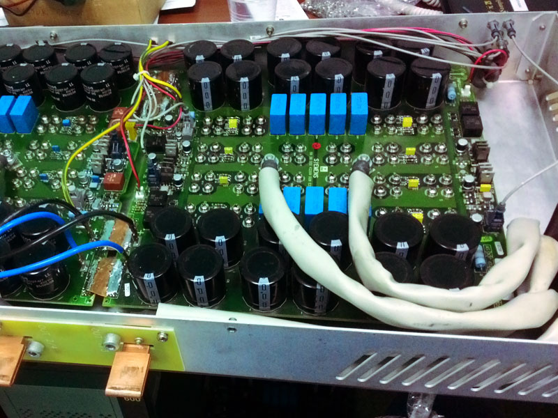
Unfortunately, I can not say the same about Siemens products. It is obvious that the engineers who designed the radio frequency amplifier device were given the task of using the cheap Buz103 transistor produced by the company. This is a frail component in terms of permissible power for it, and in order to get out of the situation, 177 transistors were inserted into the final design of the amplifier with the beautiful name “Dora”, all of which stand on two huge heatsinks that are at high voltage during operation and are in contact with radiator water cooling, and he already in turn is constantly flowing, and right on the board, which is in the photo below.
Siemens Amplifier Board power amplifier 10kW. Solid electrical show off: inductance from the tracks, going through several layers, the most complicated control circuit of transistors on a 10-layer board, resonators from polygons and other unpleasant things.
The maintainability of the amplifier of this company is practically none. Having at its disposal the production of Siemens transistors can afford to collect parts similar in parameters from the party, by selection, and this is very critical when hundreds of transistors work in parallel at once. And the most annoying thing is that even if you buy the right amount for a replacement, it turns out that what is on sale is not what it seems.
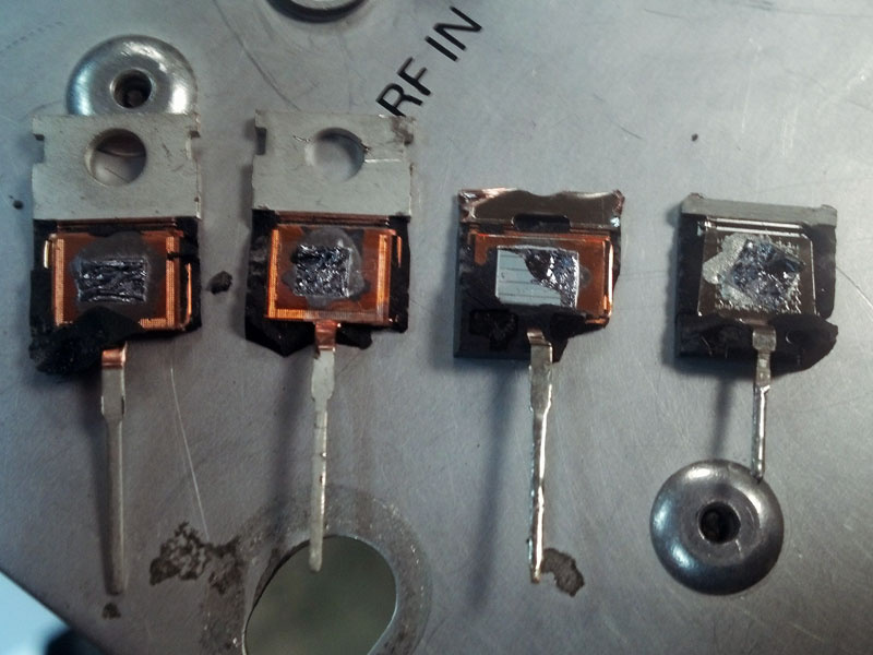
Opening transistors - all are signed on the outside and look the same, inside - all are different. The original is on the far right. Those with a smaller area of the crystal than the original - are burning like matches, the second on the right, although it has a similar area, but it works disgustingly in the amplification mode.
Probably someone may ask why the transistors used in the amplifiers described, what about lamps? Indeed, in the old units of the Siemens company, as well as in quite modern Philips devices with a field of 3T, lamps are used. Alas, I do not have a photo of this iron, but I can say that the service life of these elements is only a year or two, and they have a considerable price. In general, as the article denounced the attention of Philips, did not work out well. I will correct a little:
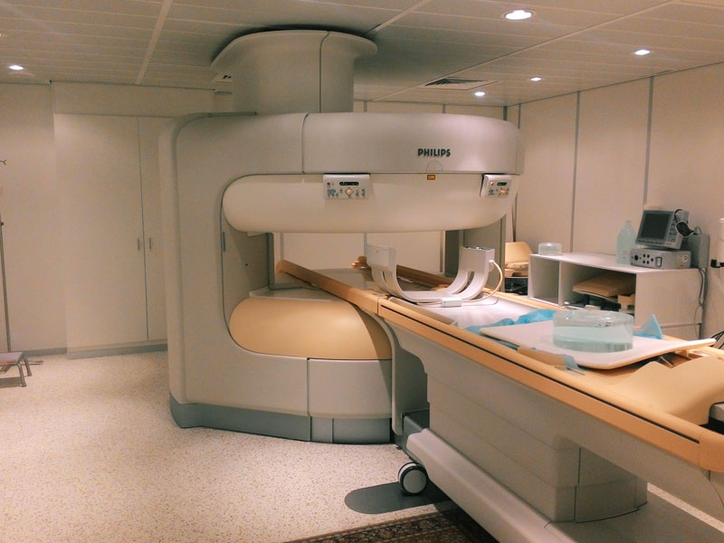
MRI of a new type - Philips Panorama. As a rule, open-type devices are based on permanent or electromagnets, which automatically means low field and picture quality. But not in this case. The field of this device is 1 Tesla, and a superconductor is also used here. A huge compared to the conventional tomograph space allows for the study of large patients, or those who are afraid of a confined space, such as children.
The power of the radio frequency signal is monitored in the power amplifier unit itself, in the measuring unit that performs trimming of the transmitting antenna (coil), and also in the receiver. Thus, the MRI apparatus has threefold protection against exceeding the permissible norms of radio emission. So do not be afraid, and safely undergo examination.
Despite the power of the amplifiers described above, the signal received in response to resonant excitation is rather small.Therefore, the transmitting antenna (Body coil), described earlier and located in the housing of the tomograph, is rarely used in the mode of signal reception. Instead, there is a large set of coils for any part of the body - head, back, knee, shoulders, etc. They are much closer to the object of study and allow you to achieve better image quality. But I think you are already tired of the heap of information, so I’ll just stick a watermelon in the scanner.
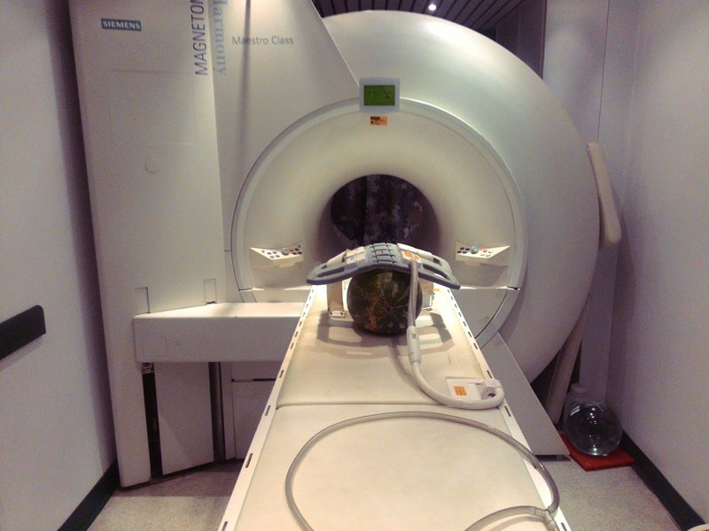
Watermelon is preparing for the study. On top of it lies a coil intended for the chest area, under it is a coil for the spinal section and the spine. On the right on the floor is a

. . ? , , , , , .

. , , .
The signal from the coils enters the receiver unit as analog signals, where they are processed into digital form. In the latest equipment on the cutting edge of progress, a receiver with an analog-to-digital converter is built right inside the coil, and an optical data line goes to the computer. This is done in order to remove interference as much as possible. A computer that builds an image from this data usually stands alone and is called a re-enactor. The resulting images are printed on film, which by the way is well suited for photoresist.
In conclusion, I also wanted to add that in Russia right now they are conducting interesting studies to improve the image quality in MRI devices. The department of nanophotonics and metamaterials of ITMO University is engaged in this. If in simple words - metamaterials are composites that have a special structure. They allow you to create antennas and resonators with very small dimensions compared with the long wavelength of radiation, which is ideal for magnetic resonance imaging.
All Articles