Step-by-step guide for setting up VKS camera guidance
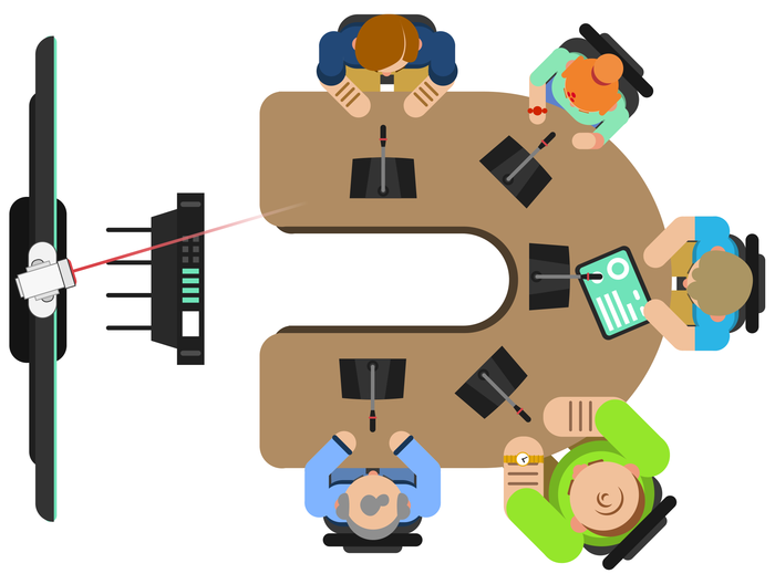
In one of the previous articles, we told in which cases it was advisable to use the congress system in the meeting rooms to capture the sound from the participants of the meeting. Recall that the main factor is the number of participants in the room, more than 10-12 people. With so many people, there is a lot of extraneous noise: the movement of chairs, coughing, rustling paper, whispering participants with each other, etc. Therefore, the means of capturing sound with a circular pattern becomes less effective, since, along with the speech of the participants, they capture extra parasitic noise.
Microphone congress consoles have a cardioid sound capture pattern.

Due to this, the sound signal is captured only on the directivity axis of the microphone, and all extraneous sounds and noises are cut off. As a result - a clear legible speech of the speaker and no one else.
A nice bonus of the BKR congress systems is the ability to control the position of the video camera without using additional expensive control systems: when activating any microphone console of the system, the video camera is automatically directed at it.
The system can control the position of not one, but several video cameras (up to 4). This feature becomes especially useful when the meeting room has an elongated shape - using a single camera gives incomplete coverage of all participants in the meeting and you have to use 2 or more cameras.

The process of setting up camera guidance on an active BKR microphone takes a little time and does not require special skills and knowledge of multimedia equipment.
In this article, we describe in detail the process of setting up automatic guidance of a single CleverMic camcorder to an active microphone using the example of the BKR WCS-20M wireless congress system.
Connecting the camera to the congress system
To begin with, the camcorder’s control function is implemented by the central unit of the congress system . Its main function is to mix the audio signal from all the microphones attached to it and transmit further (to an audio amplifier, audio mixer, computer or hardware terminal). For this, the central unit has audio outputs 1 and 2.
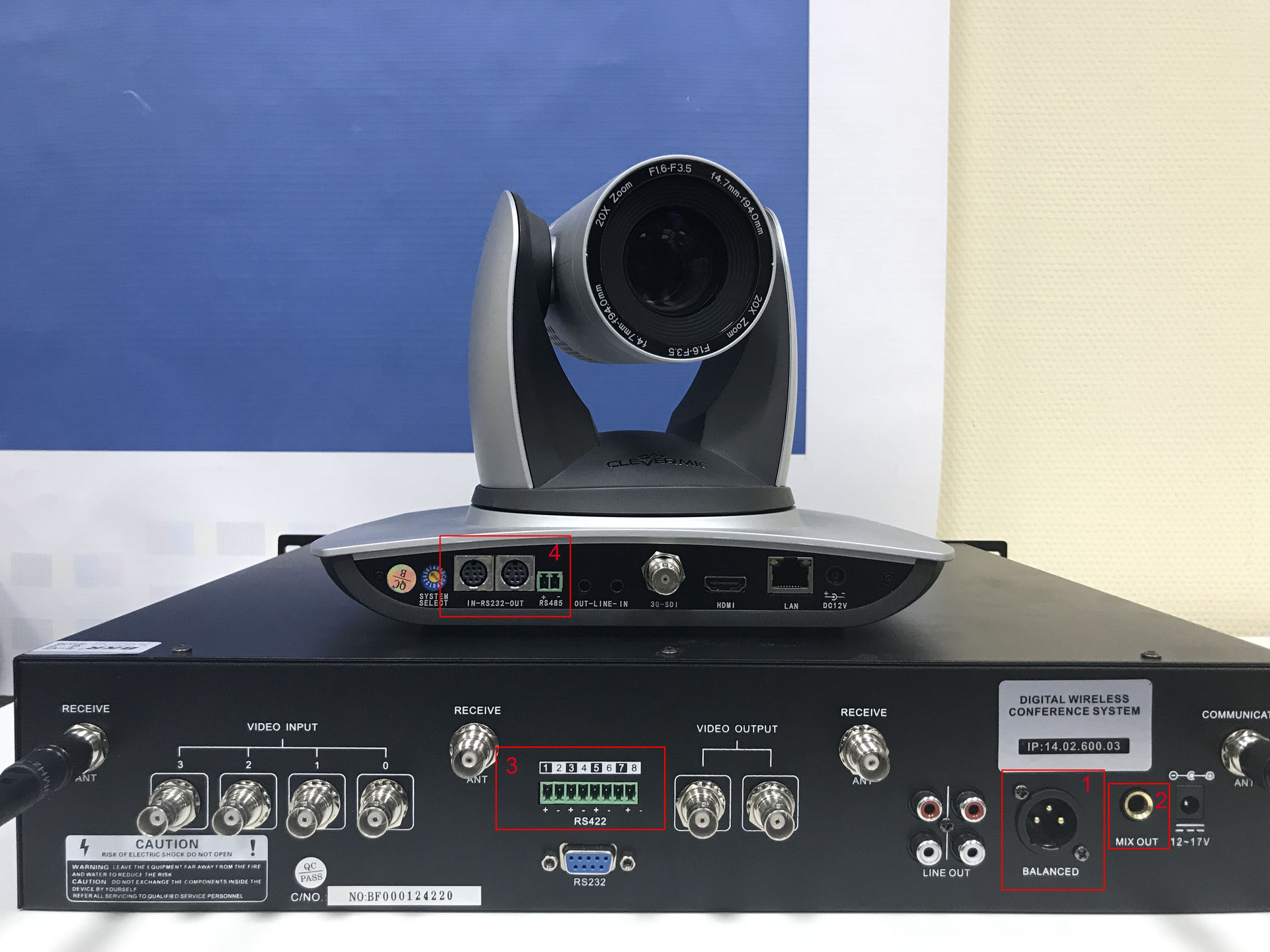
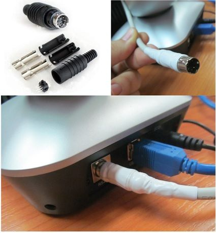
In order to control the camcorder, the unit must have special control ports. The BKR WCS-20M unit has a control port 3 implemented as dry contacts. The video camera also needs a control port, through which the camera will receive commands, to which position to transfer the PTZ camera mechanism and what degree of optical zoom to apply. All CleverMic camcorders have control ports implemented as MINI DIN 8PIN connectors (number 4 in the figure).
Connectors 3 and 4 must be connected with cables for the transmission of control signals. Any twisted pair will do for this. On the camcorder side, we use pins 6 and 8 of the MINI DIN 8PIN connector , on the side of the central unit - a pair of dry contacts, depending on which logical number is assigned to the camcorder: pins 1-2 - camera number 1, contacts 3-4 - camera number 2 and etc. In our booth, the camera had a sequence number of 4, so dry contacts 7-8 are involved.
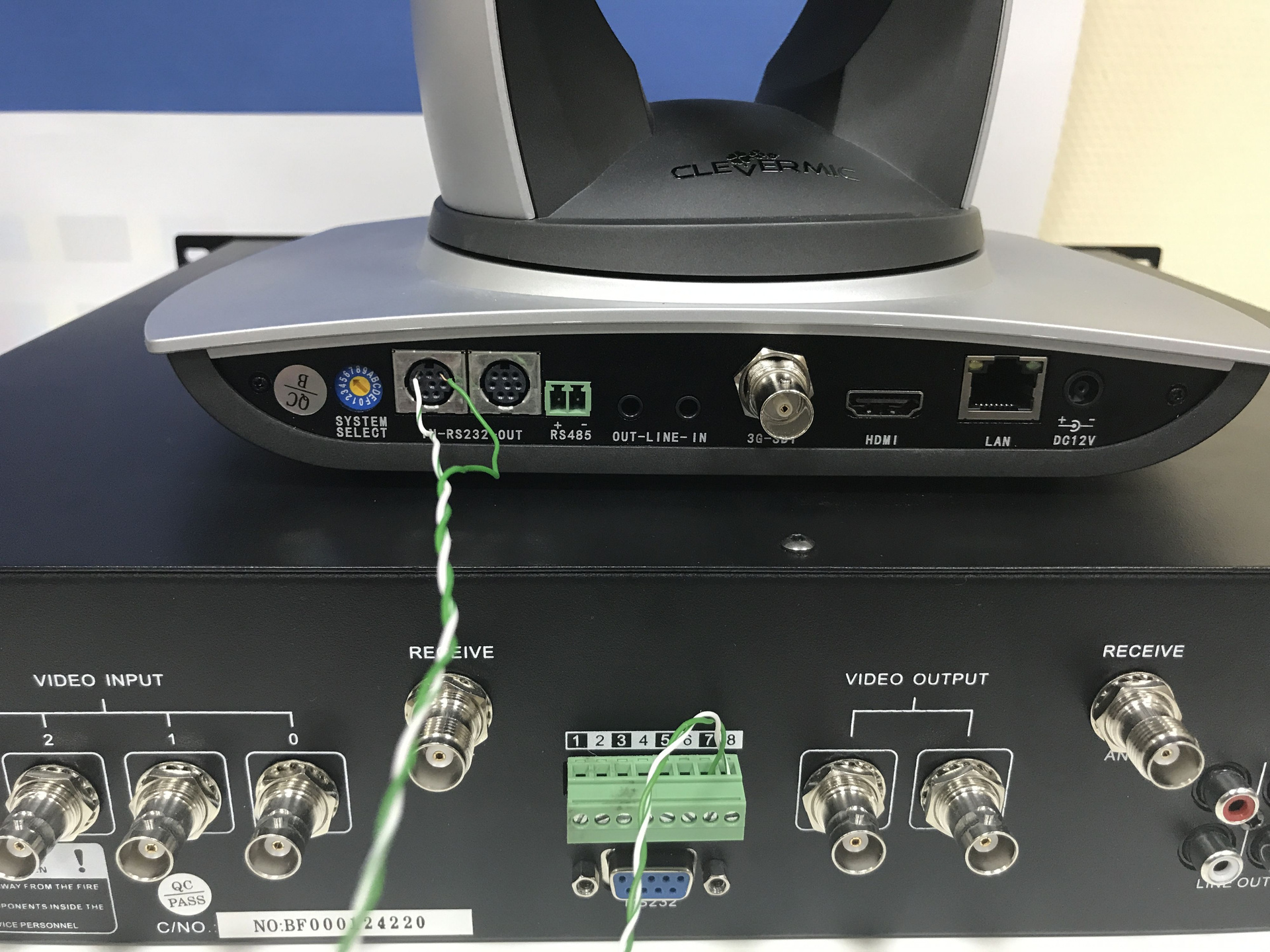
PS Of course, we used the connection with open cables only for clarity, and we do not recommend leaving connections in this form: on the side of the camera, you need to use the MINI DIN 8PIN connector
The permissible cable length between the video camera and the central unit depends on the type of control standard used:
- RS-232 / VISCA - length up to 15 meters
- RS-485 - length up to 1200 meters
The CleverMic 2012ws video camera used in the booth supports both protocols, which means it can be used in large conference rooms.
Camera guidance system setup
After the physical connection of the components, the next step is the logical setup of the equipment. It includes the following steps:
- In the camcorder settings, select the VISCA control protocol (MENU / SYSTEM / PROTOCOL - VISCA) and the logical number of the camera number 4 (MENU / SYSTEM / ADDRESS).
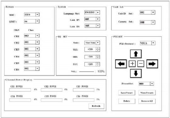
- In the settings of the central unit, put the VISCA control protocol in the PTZ-Protocol menu section.

- Carry out the process of initialization of microphone consoles:
- Turn off the central unit of the congress system.
- Turn on the microphone, make sure that it is in Standby mode and the indicator light on the gooseneck is flashing.
- Turn on the central unit.
For the logical connection of the microphone console with the central unit, a combination of two parameters is used - “LinkIP” and “LinkID”. The values of these parameters are defined in the System menu. At the factory, the manufacturer settings are set to the same value and the user does not need to configure them.
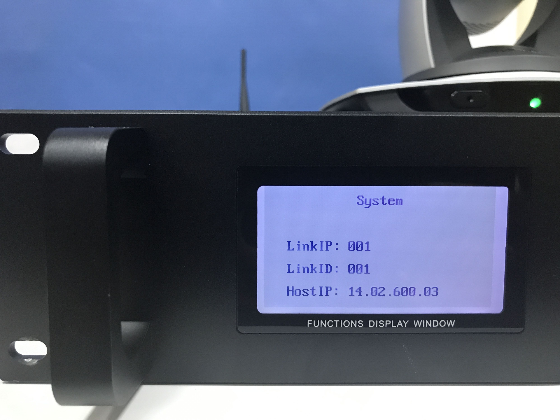
After turning on the central unit, the microphone console reads the values of the “LinkIP” and “LinkID” parameters, establishes a connection with the central unit and is ready to accept the following settings.
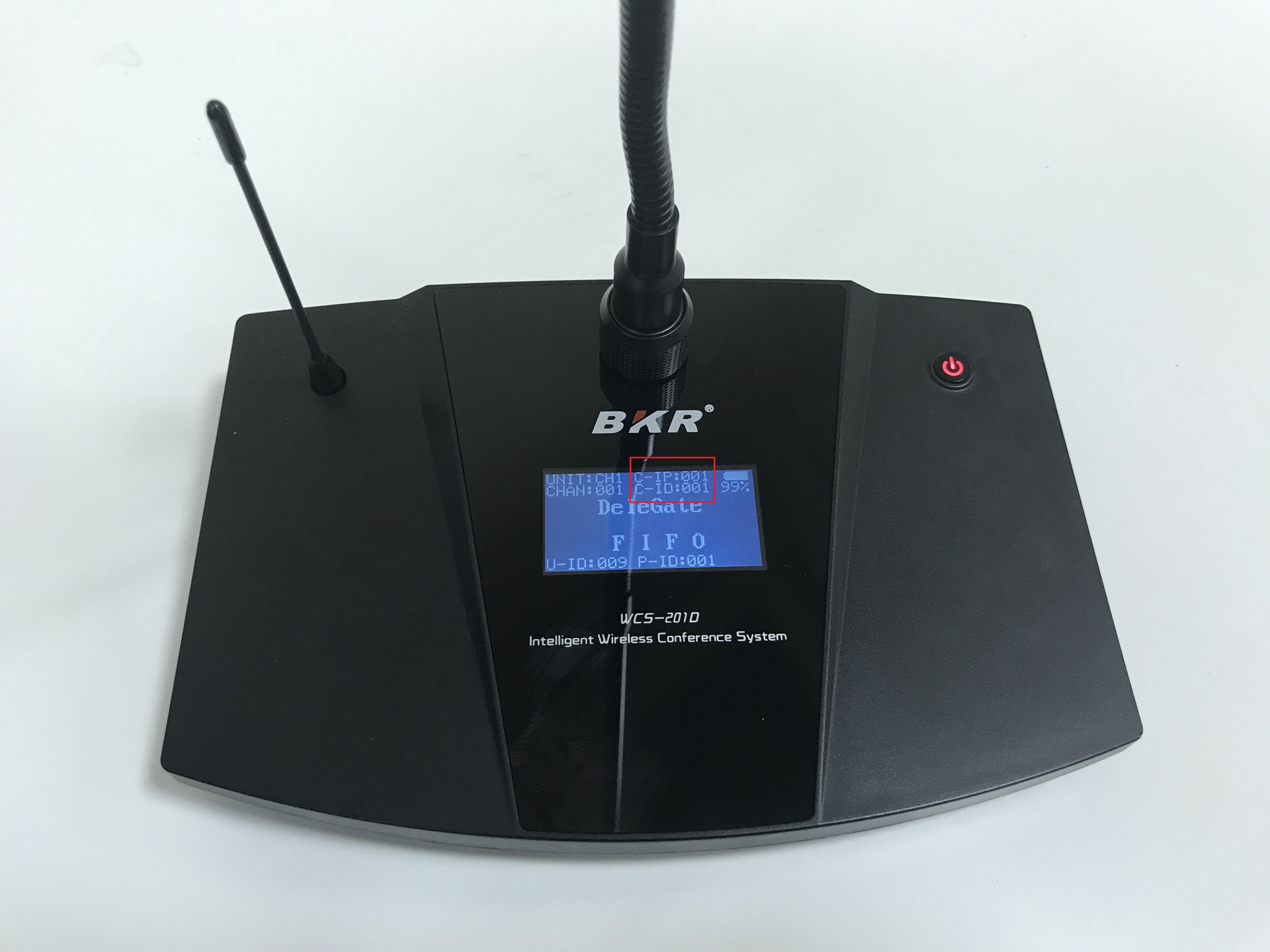
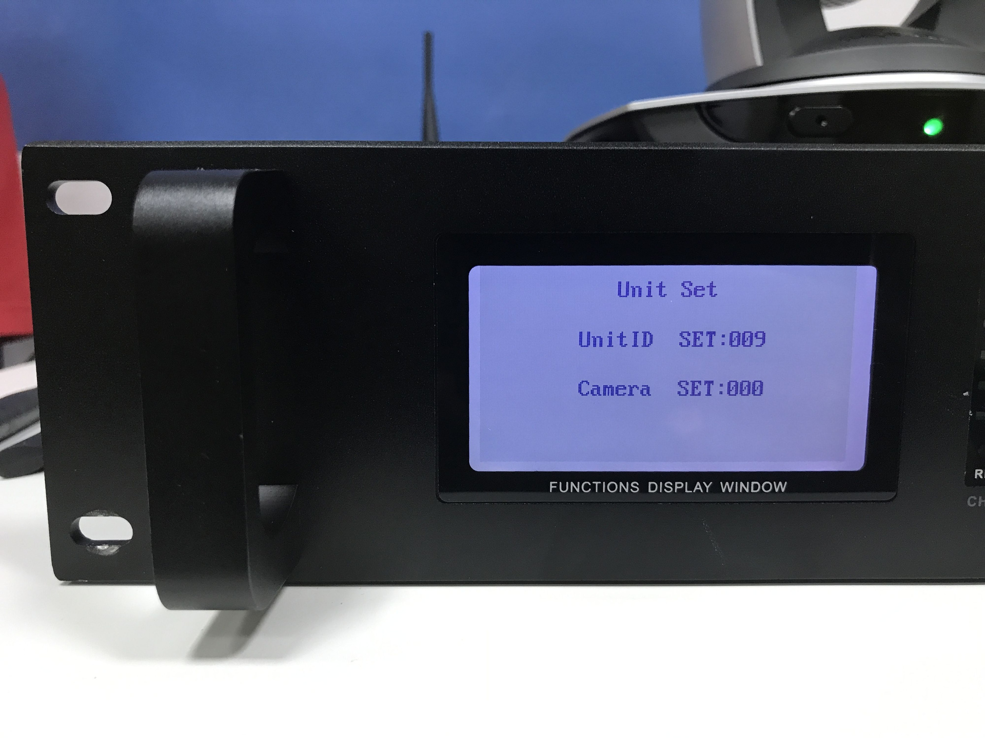
- Go to the Unit Set menu of the central unit and put the ordinal number of the microphone console, for example, 9
If the previous steps are done correctly, the microphone remote in the U-ID line will display the number 9.
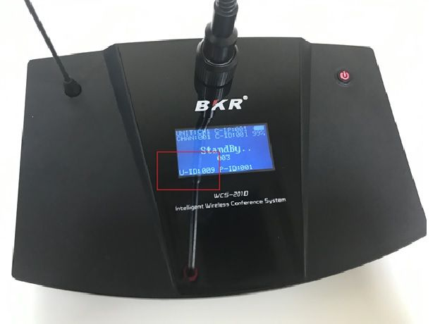
Camera SET (P-ID on the microphone remote) determines the sequence number of the video camera, which will be directed to the active microphones, and can have values from 000 to 003 (4 cameras in total).
- Using the remote control of the camera, adjust its position and optical zoom in accordance with the location of each microphone. Assign the appropriate sequence number to the camcorder position by holding down the desired key on the remote control for several seconds. For example, if the remote control ID U-ID is 9, then the position number of the video camera should also be 9.
- Perform the previous steps for each microphone system console.
- If there are more than 9 remote controls in the system, then you cannot do with the remote control to memorize the positions of the video camera. You must use the central unit management software, which can be downloaded from our website.
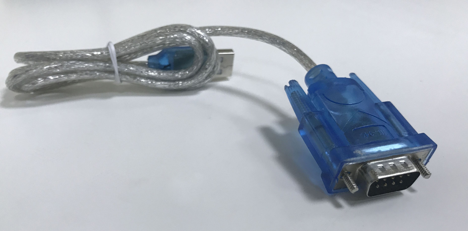
- In the case of using the setup program, you need to connect the central unit of the congress system to the computer with the cable included in the kit.
After installing the program and connecting the central unit, the system will automatically enter the system setup interface and the user will be able to configure each parameter according to his preferences.
What have we got?
Conclusion
Today, the field of video conferencing is rapidly developing and becoming available to an increasing number of companies and enterprises. This article was intended to show by example how simplified the process of setting up and maintaining multimedia equipment for professionals who have never had experience with equipment of this class.
In the next article, we will continue to develop the topic of automatic camera pointing and discuss two interesting solutions in this area, developed by our company .
You can turn with your task to the author of this article, Tatiana Usikova
usikova@unitsolutions.ru , and get not only professional advice, but also a discount on equipment for the promotional word unitfix.
All Articles