We connect a sports simulator to a computer and stop growing fat while playing computer games.

The idea of making a slouching player move into computer games is not new, Microsoft has already had Kinect for a long time, Sony and Nintendo have all sorts of sensors, and now accessories for virtual reality helmets that require you to move your arms and legs during the game.
However, personal experience using such devices has shown that:
1. You can play only those games that are clearly sharpened by motion sensors. And what about those whose favorite game is "Funny Zombies on the Island of the Innocent", released in the last century?
2. The movements in the game do not coincide with the comfortable / necessary level of load. Either you get tired quickly or your muscles do not get the necessary load.
Therefore, I came up with the idea to connect the simplest compact sports simulator (stepper) with a computer and make the computer allow me to play only when I observe a certain exercise pace.
As a result, on the first day of using the device, I took more steps than in a year of irregular sluggish approaches to a similar simulator at lunchtime, and a month later I smashed rubber stoppers. Well, I didn’t continue the hole in the floor and didn’t fall to the neighbors from the bottom.
Who cares to repeat my experience - read on.
Briefly about how it works
When you step on the stepper, the magnet moves in it, closing and opening the built-in sensor (reed switch), thereby counting and displaying the number of steps.
Install a similar sensor next to it, connect it to the Arduino board, and let it be connected to the computer with a USB cable. Arduino will inform the program on the computer when you take the next step. If you are not walking too intensively, the program instructs Arduino to first draw your attention to the blinking LEDs (red, then blue, then both), and then turn on the annoying squeak. If this does not help, the program darkens the image on the computer screen.
Believe it works well. You immediately resume walking.
Initially, I tried to block the mouse / keyboard work as a punishment for low intensity exercise. But it turned out to be superfluous / annoying; it is enough to slightly lower the comfort of communicating with the computer, but not to block control altogether.
Experience of use and prospects
I began to move much more, and this is definitely a plus. But there are subtleties.
Inexpensive stepper, unfortunately, changes its characteristics in the first minutes of use. The oil in the shock absorbers heats up, it becomes thinner, and it becomes easier to move. I even have it written on the stepper box that it is designed for 20 minutes of continuous use.
The program is currently configured at one load rate. Ideally, it should be adjusted both manually and on schedule. And even better - depending on the pulse sensor.
Further, the legs train well enough. But what about the hands and everything else? After all, the hands are busy with the keyboard and mouse?
I tried to free my hands using computer control by tracking the direction of my gaze and voice. Well ... You can play chess like this on a computer, but I didn’t succeed in a dynamic game.
Watch videos about trying to play hands-free (using programs I wrote for people with disabilities)
Voice control in the game:
Controlling the look in the game:
Controlling the look in the game:
So while the load on the hands is an open question. Perhaps I will try to place the buttons / pressure sensors / gyroscopes directly on the arms of the simulators.
In general, I believe that fitness centers, in the form in which they are now, have outlived themselves. The time of entertainment centers will come, where physical activity will be stimulated by some kind of entertainment, for example, computer games / competitions.
For now - we will do this at home.
What do we need?
1. A computer mounted on an elevation. It is important. Standing on the stepper, you should have comfortable access to the keyboard and mouse. I built a shelf on the wall bars.
2. The stepper simulator. I took the “Domyos Mini Stepper Essential” in the “Decathlon”. But I saw a very similar model in the "Sportmaster". In general, it seems that all steppers are made according to the same drawings, making minimal cosmetic changes.
3. A set with the Arduino board is the easiest, if only there were:
- Arduino board (in my case - the Chinese equivalent of Arduino Nano)
- USB cable for connecting to computer
- circuit board and wires
- 2 LEDs, 2 resistances 220 Ohms, 1 resistance 10 kΩ
You can take all these elements separately.
4. piezo emitter, designed for voltages from 5 volts. On my written - HPM-14A.
5. miniature reed switch, for example, -10110. A larger reed switch does not work well here! Verified!
6. long two-wire cable to connect the reed switch in the simulator and the Arduino
7. A cap from an old felt-tip pen to place a reed switch in it
8. Soldering iron, drill, tweezers, glue gun, tester / multimeter.
Step-by-step instruction
1. Add reed switch to stepper
Gently bend one of the reed switch's terminals, holding it with tweezers at the base so that the glass case will not crack when bent! I am one reed switch so lost.

We solder the wires:
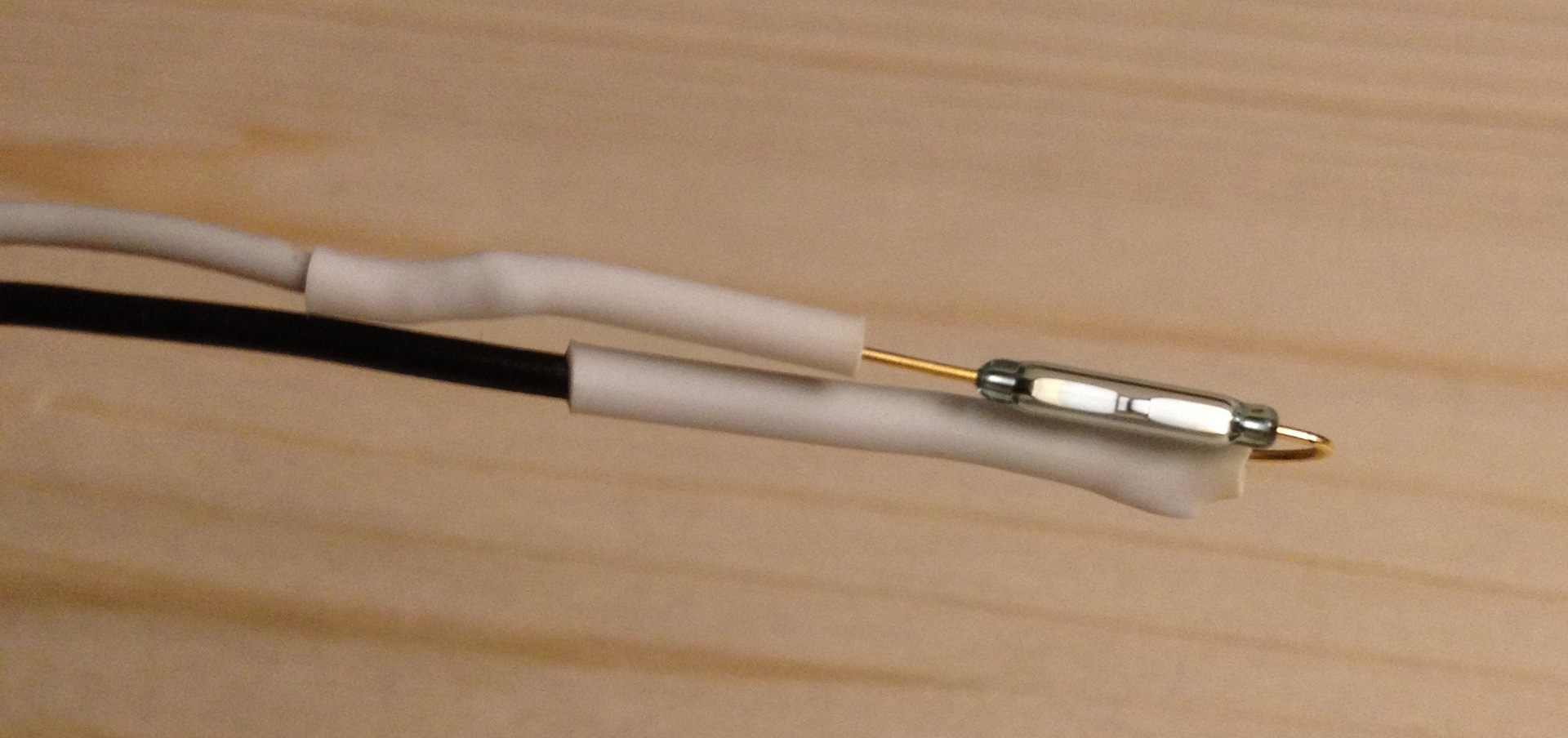
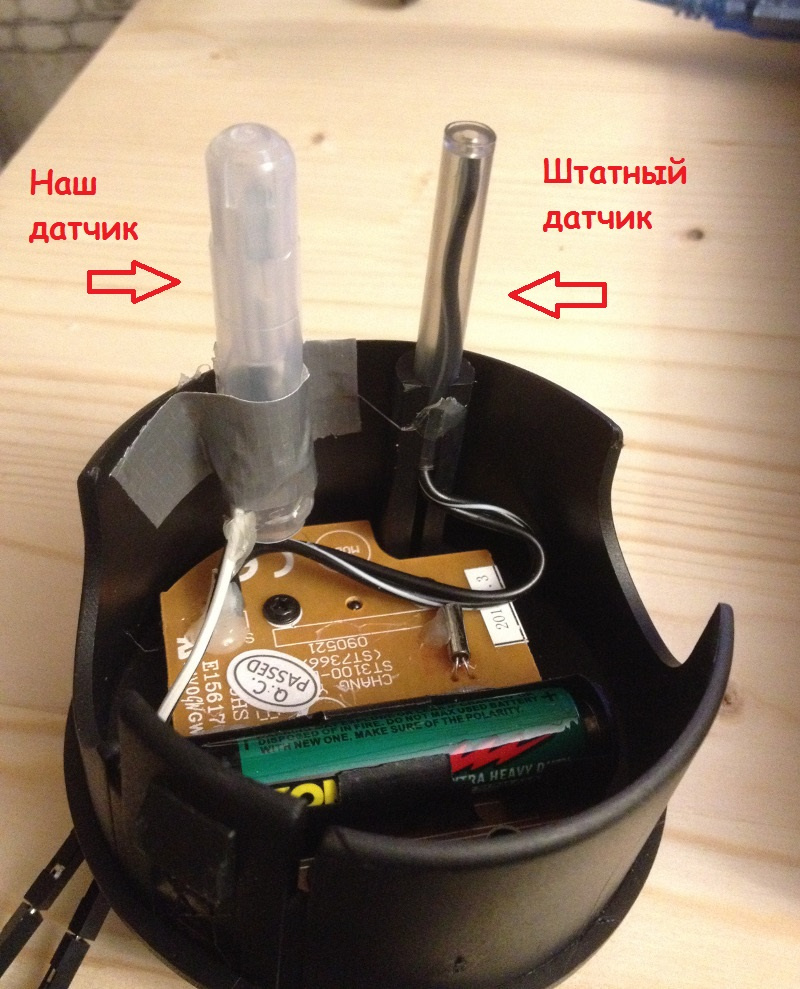
We put the reed switch in the cap from the felt-tip pen and install it, similarly to the standard one, but from the other side. Immediately set to the right place will not work. The right place is when the reed switch is triggered exactly in the middle of a step, when the right pedal is flush with the left. Therefore, we first glue with adhesive tape and move it left and right until we find the correct position (we need a tester to see when the contact closes and opens):
Then finally fix the cap with the sensor, pouring glue from the glue gun. While the glue is not completely frozen, it is still possible to slightly adjust the position of the sensor.
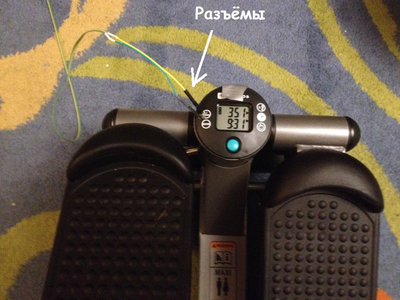
It makes sense to provide the wires from the sensor that are brought out through the drilled hole with easily detachable connectors (taken from the Arduino kit). Then many times he touched the wire with his foot, and this saved him from the cliff.
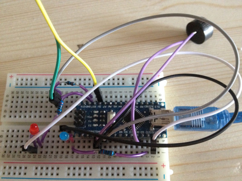
2. We assemble the circuit with the Arduino board

I turned it into such an interlacing of wires:
3. Fill the program in Arduino
Program code
// , int brightnessB=LOW, brightnessR=LOW; int blinkingB=0; int blinkingR=0; int speakerPin=8; int BlueLED=10; int RedLED=11; int freq[]={3830,3038,2550,3038}; int cur_freq=0; int buzzer_value=0; volatile int stepper=0, old_stepper=0; // pin void step() { stepper=!stepper; Serial.print(stepper); Serial.flush(); } void setup() { pinMode(10,OUTPUT); pinMode(11,OUTPUT); pinMode(2,INPUT); Serial.begin(9600); //attachInterrupt(0,step,CHANGE); } void loop() { delay (200); // 1. while(Serial.available()) { switch(Serial.read()) { case '0': // , brightnessB=HIGH; blinkingB=0; brightnessR=HIGH; blinkingR=0; buzzer_value=1; break; case '1': // . brightnessB=LOW; blinkingB=1; brightnessR=HIGH; blinkingR=1; buzzer_value=0; break; case '2': // brightnessB=HIGH; blinkingB=1; brightnessR=LOW; blinkingR=0; buzzer_value=0; break; case '3':// brightnessB=LOW; blinkingB=0; brightnessR=HIGH; blinkingR=1; buzzer_value=0; break; case '4': // brightnessB=LOW; blinkingB=0; brightnessR=HIGH; blinkingR=0; buzzer_value=0; break; case '5': // . brightnessB=LOW; blinkingB=0; brightnessR=LOW; blinkingR=0; buzzer_value=0; break; } } // , , if(1==blinkingB) { if(HIGH==brightnessB) brightnessB=LOW; else brightnessB=HIGH; } if(1==blinkingR) { if(HIGH==brightnessR) brightnessR=LOW; else brightnessR=HIGH; } digitalWrite(RedLED,brightnessR); digitalWrite(BlueLED,brightnessB); if(1==buzzer_value) { tone(speakerPin, freq[cur_freq], 200); cur_freq++; if(cur_freq>3) {cur_freq=0;} } stepper=digitalRead(2); if(old_stepper!=stepper) { Serial.print(stepper); Serial.flush(); old_stepper=stepper; } }
Checking that it works - in Serial Monitor, which is in the Arduino development environment, you can see a growing string of zeros and ones when you step on the simulator.
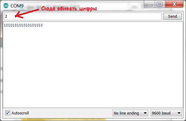
And if you drive in numbers and send them to the Arduino, then it should react like this:
5 - LEDs are off
4 - lit red
3 - blinking red
2 - blinking blue
1 - blinks red or blue
0 - Beeper squeaks. Both diodes are on.
4. Run the program on the computer
The DimForce.exe program can be taken on a githaba (including in the form of sources):
https://github.com/MastaLomaster/DimForce
Currently, the program is hard-coded that the Arduino is connected via COM9. If this is not your case, configure the Arduino port as COM9. Or recompile the program by correcting the line in the DFSerial.cpp file:
Port = CreateFile(L"\\\\.\\COM9", GENERIC_READ | GENERIC_WRITE, 0, NULL, OPEN_EXISTING, FILE_FLAG_OVERLAPPED, NULL);
When you step on the simulator, in the program window zero should change by one and back:

If you stop pacing, the LEDs should blink more and more annoyingly, and then the squeaker will turn on, and in the end the screen will darken a little.
Do not stop! Take care of your health!
All Articles