
開発プラットフォームは、esp8266によって選択されました。これは、wifiが必要であり、その価格が許容できるからです!
ファームウェアはLUAで使用され、アセンブリはカスタムでした(サポートされているライブラリのリストにI2CとBITを含めることを忘れないでください)。
サーボはPWMによって制御されることがわかっているため、esp8266にはオンボードのPWMに問題がありますが、少なくともI2Cがあり、自転車などを発明する理由として、12ビット16チャネルインターフェイスを搭載したPCA9685コントローラーが見つかりました+外部電源、I2C、サーボを制御するために他に必要なものはありません!
GooglingはarduinoのPythonでPCA9685を操作するためのライブラリを見つけました。Luaについては1つしか言及されていません。
誰がPCA9685の説明に興味がなく、彼は主題にいる、彼はすぐに回る 。
理解のためのコントローラーの説明:
既に理解しているように、コントローラーはI2Cプロトコルに従って動作します。PCA9685の場合のコントローラーの動作の本質は、読み取りまたは書き込みのためのレジスター番号の転送です
-- read = function (this, reg) -- I2C i2c.start(this.ID) -- if not i2c.address(this.ID, this.ADDR, i2c.TRANSMITTER) then return nil end -- ( , ) i2c.write(this.ID, reg) -- i2c.stop(this.ID) -- I2C i2c.start(this.ID) -- if not i2c.address(this.ID, this.ADDR, i2c.RECEIVER) then return nil end -- 1 c = i2c.read(this.ID, 1) -- i2c.stop(this.ID) -- return c:byte(1) end, -- write = function (this, reg, ...) i2c.start(this.ID) if not i2c.address(this.ID, this.ADDR, i2c.TRANSMITTER) then return nil end i2c.write(this.ID, reg) len = i2c.write(this.ID, ...) i2c.stop(this.ID) return len end,
作業については、設定を担当する3つのレジスタ(0x00、0x01、および0xFE)、およびPWMを担当するペアで機能するいくつかのタイプ(アドレスでグループ化)のレジスタにのみ関心があります。 !
レジスタの内容、バイトとビット、その操作方法とその内容に関する詳細情報
ルールは簡単です!
1レジスタ-1バイトの情報
レジスタが何であるかを理解していない人、これは特定のメモリ領域のアドレスを含む同じ1バイトです。それらはすべて16進数で表されます。つまり、一般的な理解のために10進数に変換できます。
また、0x06と0x07などの2つのレジスタを受け入れるパラメーターもあります。これらは現在、チャンネル0のPWMイネーブルポイントを担当しています。
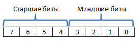
ビットが何であるかわからない人のために、それらのバイト数はバイト数です。
1バイト -8ビット ( 右から 左 への番号付け)では、0から始まります。つまり、0から7までの8ビットがあり、 最 上位ビットは左側に、 最下位ビットは右側にあります。 2バイトで記述された特定のパラメーターがある場合、そのうちのどれが最上位ビットを担当し、どのビットが最下位ビットを担当するかを理解する必要があります!
例(パラメーターが1つのレジスターで記述されている場合):
特定の45があります。特定のレジスタに書き込む必要があります。どのビットが書き込まれるかを理解するために、これをすべて2桁のシステムと16 桁のシステムに変換しましょう。
45→ 00101101
それぞれ8個のビットセットを取得しました。これらのバイトは特定のアドレスのレジスタに書き込まれます
45→0x2D(値)
例(パラメーターが2つのレジスターで記述されている場合):
コントローラーは12ビットなので、256以上から1バイトを超える数を取得してみましょう。
3271→0000 1100 11000111
ご覧のとおり、各8ビット、つまり16ビットを2回取得しました。最初の12ビットのみに関心があるため、最後の4ビットを安全に破棄できます。右から左へ、つまり この値を各レジスタに個別に書き込まれる2バイトに分割するには、これらのビットを2つの部分に分割する必要があります
1) 1100 →0x0C(上位4ビット)
2) 11000111 →0xC7(下位8ビット)
Luaは、ビット単位演算を使用してこの分離を実装します。
-- bit.rshift(3271, 8) -- 00001100 11000111 -> 00001100 -- -- 00001100 -- bit.band(3271, 0xFF) -- 00001100 11000111 -- 11111111 -- -- 00000000 11000111
パラメーターの詳細:
上記のように、3つのレジスタを使用することを検討します
3) 0xFE -PWM周波数を担当(PRE_SCALE)
PWM周波数を設定するには、クロックソースを使用し、内部クロックソースは25 MHzの周波数で動作します。レジスタに転送される値は、式によって計算されてから、レジスタに書き込まれる必要があります。
値PRE_SCALEの計算
\ begin {eqnarray}
PRE \ _SCALE&=&round(\ frac {F_ {osc}} {4096 * F_ {pwm}})-1
\ end {eqnarray}
Fosc = 25,000,000
Fpwm =希望のPWM周波数
4096-12ビットに含まれる値の数
つまり、周波数を50Hzに設定します
\ begin {eqnarray}
PRE \ _SCALE&=&round(\ frac {25000000} {4096 * 50})-1 = 121
\ end {eqnarray}
レジスタ0xFEに値121 (0x79)を書き込む必要があります。
Fpwmの計算
\ begin {eqnarray}
F_ {pwm}&=&\ frac {F_ {osc}} {4096 *(PRE \ _SCALE + 1)}
\ end {eqnarray}
\ begin {eqnarray}
F_ {pwm}&=&\ frac {25000000} {4096 *(121 + 1)} = 50
\ end {eqnarray}
getFq = function(this) local fq = this:read(this.PRE_SCALE) return math.floor(25000000 / ( fq + 1) / 4096) end, setFq = function(this, fq) local fq = math.floor(25000000 / ( fq * 4096 ) - 1) local oldm1 = this:read(0x00); this:setMode1(bit.bor(oldm1, this.SLEEP)) this:write(this.PRE_SCALE, fq) this:setMode1(oldm1) return nil end
レジスタ0x00および0x01を操作するための関数
getMode1 = function(this) return this:read(0x00) end, setMode1 = function(this, data) return this:write(0x00, data) end, getMode2 = function(this) return this:read(0x01) end, setMode2 = function(this, data) return this:write(0x01, data) end, getChan = function(this, chan) return 6 + chan * 4 end,
1) 0x00-パラメーター
7ビット-再起動
6ビット-EXTCLK
5ビット-AI
4ビット- スリープ
3ビット-SUB1 *
2ビット-SUB2 *
1ビット-SUB3 *
0ビット-ALLCALL
RESTART-再起動フラグを設定します
EXTCLK-使用、 -1外部 、 0内部クロックソース
AI-レジスタにデータを書き込むときのレジスタの自動インクリメントを有効(1)および無効(0)にします。 最初のレジスタのアドレスを使用して、 2バイトをすぐに送信できます。2バイトはレジスタアドレス+ 1に書き込まれます。
SLEEP-コントローラーを省電力モードに切り替える(1)、またはその逆(0)
ALLCALL- (1)モジュールが一般的な呼び出しアドレス(PWMで動作)に応答できるようにします。そうでない場合は0
*-考慮しない
-- MODE 1 reset = function(this) local mode1 = this:getMode1() mode1 = bit.set(mode1, 7) this:setMode1(mode1) mode1 = bit.clear(mode1, 7) this:setMode1(mode1) end, getExt = function(this) return bit.isset(this:getMode1(), 6) end, setExt = function(this, ext) local mode1 = this:getMode1() if (ext) then mode1 = bit.clear(mode1, 6) else mode1 = bit.set(mode1, 6) end this:setMode1(mode1) end, getAi = function(this) return bit.isset(this:getMode1(), 5) end, setAi = function(this, ai) local mode1 = this:geMode1() if (ai) then mode1 = bit.clear(mode1, 5) else mode1 = bit.set(mode1, 5) end this:setMode1(mode1) end, getSleep = function(this) return bit.isset(this:getMode1(), 4) end, setSleep = function(this, sleep) local mode1 = this:geMode1() if (sleep) then mode1 = bit.clear(mode1, 4) else mode1 = bit.set(mode1, 4) end this:setMode1(mode1) end, getAC = function(this) return bit.isset(this:getMode1(), 0) end, setAC = function(this, ac) local mode1 = this:geMode1() if (ac) then mode1 = bit.clear(mode1, 0) else mode1 = bit.set(mode1, 0) end this:setMode1(mode1) end,
2) 0x01-パラメーター
7ビット-使用されていません
6ビット-使用されていません
5ビット-使用されていません
4ビット-INVRT
3ビット-OCH
2ビット-OUTDRV
1、0ビット-OUTNE
INVRT-出力での信号の反転、(0)-反転オフ、(1)-反転オン
OCH -I2CチャネルでPWMの値を適用する方法(ASKで1、STOPで0)
OUTDRV-外部ドライバーなしで外部ドライバーを接続する機能(1)
OUTNE-外部ドライバーの接続タイプ(0-3)
-- MODE 2 getInvrt = function(this) return bit.isset(this:getMode2(), 4) end, setInvrt = function(this, invrt) local mode2 = this:geMode2() if (invrt) then mode2 = bit.clear(mode1, 4) else mode2 = bit.set(mode1, 4) end this:setMode2(mode2) end, getInvrt = function(this) return bit.isset(this:getMode2(), 4) end, setInvrt = function(this, invrt) local mode2 = this:geMode2() if (invrt) then mode2 = bit.clear(mode2, 4) else mode2 = bit.set(mode2, 4) end this:setMode2(mode2) end, getOch = function(this) return bit.isset(this:getMode2(), 3) end, setOch = function(this, och) local mode2 = this:geMode2() if (och) then mode2 = bit.clear(mode2, 3) else mode2 = bit.set(mode2, 3) end this:setMode2(mode2) end, getOutDrv = function(this) return bit.isset(this:getMode2(), 2) end, setOutDrv = function(this, outDrv) local mode2 = this:geMode2() if (outDrv) then mode2 = bit.clear(mode2, 2) else mode2 = bit.set(mode2, 2) end this:setMode2(mode2) end, getOutNe = function(this) return bit.band(this:getMode2(), 3) end, setOutNe = function(this, outne) local mode2 = this:geMode2() this:setMode2(bit.bor(mode2, bit.band(outne, 3))) end, getMode2Table = function(this) return { invrt = this:getInvrt(), och = this:getOch(), outDrv = this:getOutDrv(), outNe = this:getOutNe(), } end,
PWMを使用する
コントローラーには16のチャネルがあり、各チャネルに4つのアドレスが割り当てられます。そのうち2つはオンで、2つはオフです
例:
0チャンネル
含めるための登録
0x06 (L、下位8ビット)
0x07 (H、最上位 4ビット)
シャットダウンレジスタ
0x08 (L、下位8ビット)
0x09 (H、上位4ビット)
したがって、各レジスタアドレスの+4は、特定のチャネル上の特定のタイプのレジスタのアドレスです。
PWMを操作するための関数
-- CNAHEL setOn = function(this, chan, data) this:write(this:getChan(chan), bit.band(data, 0xFF)) this:write(this:getChan(chan) + 1, bit.rshift(data, 8)) end, setOff = function(this, chan, data) this:write(this:getChan(chan) + 2, bit.band(data, 0xFF)) this:write(this:getChan(chan) + 3, bit.rshift(data, 8)) end, setOnOf = function(this, chan, dataStart, dataEdn) this:setOn(chan, dataStart) this:setOff(chan, dataEdn) end,
したがって、モジュールを操作する簡単な例
-- require('pca9685') -- , i2c pca = pca9685.create(0, 0x40) -- GPIO c SDA SCL pca:init(1, 2) -- pca:setMode1(0x01) pca:setMode2(0x04) -- pca:setFq(50) -- pca:setOnOf(0, 200, 600)
PS明確化とコメントを歓迎します。より簡単な説明を見つけることができなかったため、OUTDRVとOUTNEについてのより詳細な説明に特に感謝します。