なぜArduinoなのか? 結局のところ、多くのコントローラーがより高速で安価です。 そのような場合、私は通常答えます: -安くて、実用的で、速い。
実際、結局のところ、Arduino Pro Miniの価格は1ピースで1.63ドル(最近送信)、atmega8の価格は1ドル(卸売価格)です。 ボディキット(クォーツ、コンデンサー、スタビライザー)を備えたPro Miniボードはそれほど高価ではないことがわかり、さらに時間を節約できます。 また、ArduinoのIDEシェルは多くの時間を節約し、学校の学生でも簡単かつ迅速に対応できます。 人気と安さを考えて、私はそれをArduinoで組み立てることにしました。
はんだ付けステーションを作成するには、まずはんだ付けステーションのハンドルが必要です。多くの場合、これらは907 A1322 939などの中国製ステーションです。

始めましょう
ハンドル機能:
電圧:24V DC
電源:50W(60W)
温度:200℃〜480℃
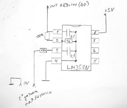
はんだごてのハンドルを制御するには、まず温度センサーからデータを取得する必要があります。LM358Nはこれを支援します。 このスキームは、ほぼ2年間、私のために既に機能しています。
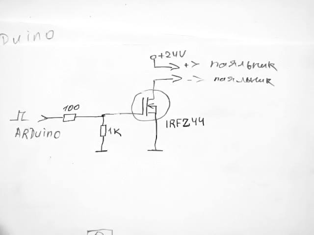
次に、はんだごての発熱体を制御(オン/オフ)する必要があります。IRFZ44パルストランジスタがこれに役立ちます。 接続は非常に簡単です。
発熱体の将来の動作モードに注目してください。 PWM変調により、3段階で組み込みます。 プログラムの開始時に、ほぼ最大の電力がオンになり(デューティサイクル90%)、設定温度に近づくと電力が減少し(デューティサイクル35-45%)、電流と設定温度の差が最小になると、電力は最小に維持されます(デューティサイクル30-35%)。 したがって、過熱の慣性を排除します。 繰り返しますが、はんだ付けステーションはほぼ2年間安定して動作しており、熱電対の最大負荷は一定ではありません(寿命が延びます)。 プログラムのすべての設定を編集できます。
スキームに従ってハンドルを接続する必要があります。

ハンドルではなく、ステーションパネルのコネクタに注意してください。
私は本当に主張します:開始する前にハンドルをチェックし、ねじりを解いて、発熱体の完全性、およびコネクタ上のワイヤの正しい配線をチェックします。
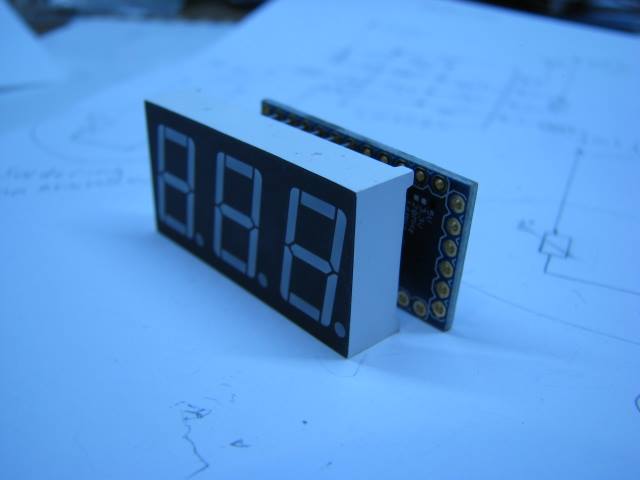
次に、コントローラーが必要です。 デモンストレーションには、最も人気があり便利なArduino Unoを選択しました。 はんだ付けステーションブロックを作成すると、コントローラーを自分で選択できるようになります。 また、10 kOhmの+ 5 V抵抗にプルアップされた2つのボタンと、3桁の7セグメントインジケーターも必要です。 100オームの抵抗を介してセグメントの結果を結び付けました。
アノード:
D0-a
D1-b
D2-c
D3-d
D4-e
D5-f
D6-g
D7-dp(ドット)
カソード:
D8-カソード3
D9-カソード2
D10-カソード1
また、アナログピン3および2にボタンを配置していることにも注意してください。プログラムでは、それらをアナログとして問い合わせます。 若い世代を誤解させないためにこれをしました。 ピン14、15、および16の場所を誰もが知っているわけではありません。また、十分な速度があり、コントローラーに多くのメモリがある場合、それは簡単です。
何が起こったのか見てみましょう:
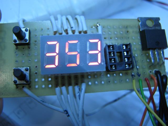
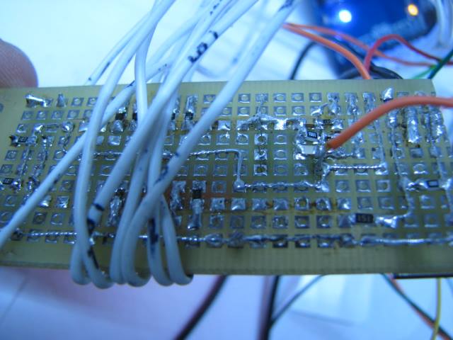
インジケータの近くに空のソケットがあることに気付くことができます。これはLM358Nのブランクです。KA358アナログのみが作業中に悪い結果を示しました。 そこで、LM358Nの温度センサーブロックをヘアドライヤー付きのはんだ付けステーションに使用しました。


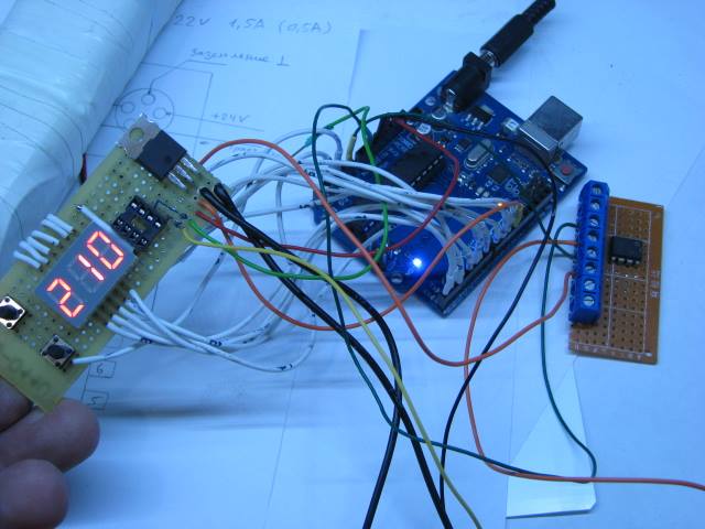
次に、電源を選択する必要があります。 22V 3Aのラップトップから電源を取りましたが、余裕を持って十分です。 はんだごての開始時の消費は1.5 Aで、温度は0.5 Aに維持されます。 したがって、適切な電源、できれば24V DC 2Aを選択してください。
上の写真では、ワイヤーハーネスを見ることができ、多くの人を怖がらせています。 理解してください、これはデモであり、任意のコントローラーのオプションであり、ステーションはコンパクトに組み立てることができます、例えば:

これは、はんだ付けステーションプロジェクトの実装の良い例です。 自分自身を組み立てる方法を理解するのに明らかに役立つビデオ:
これは、バージョンIDE 1.5.2で作成されたテストプログラムです。 上記のすべてを考慮し、あまり批判しないでください(プログラムを簡単かつ簡単に記述しようとしました)。
/* // ANODES: D0 - a D1 - b D2 - c D3 - d D4 - e D5 - f D6 - g D7 - dp (digital point) a ******** * * f * * b * g * ******** * * e * * c * d * ******** # dp CATHODES: D8 - cathode 3 D9 - cathode 2 D10 - cathode 1 */ // -------------------------------------------------- , ----------------------------------------------- byte const digits[] = { B00111111,B00000110,B01011011,B01001111,B01100110,B01101101,B01111101,B00000111,B01111111,B01101111}; int digit_common_pins[]={8,9,10}; // ( ) int refresh_delay = 5; int count_delay = 300; // COUNTING SECONDS IF count_delay = 1000 long actual_count_delay = 0; long actual_refresh_delay = 0; int increment = 0; // int max_digits =3; // - int current_digit=max_digits-1; int increment_max = pow(10,max_digits); // -------------------------------------------------- , ----------------------------------------------- //--------------------- ----------------------------- int knup = 3; // in( ) int kndn = 2; // in( ) int nagr = 11; // ( ) int tin = 0; // IN Analog LM358N int tdat = 0; // int ustt = 210; // (+ ) int mintemp = 140; // int maxtemp = 310; // int nshim = 0; // void setup(){ pinMode(nagr,OUTPUT); // () analogWrite(nagr, nshim); // ( 0 - - ) // -------------------------------------------------- , ----------------------------------------------- DDRD = B11111111; for (int y=0;y<max_digits;y++) { pinMode(digit_common_pins[y],OUTPUT); digitalWrite(digit_common_pins[y], HIGH); } // -------------------------------------------------- , ----------------------------------------------- } void loop() { show(increment); // (LED) if (tdat < ustt ){ // : if ((ustt - tdat) < 16 & (ustt - tdat) > 6 ) // , // 10 , { nshim = 99; // ( 0-255, 99) - } else if ((ustt - tdat) < 7 & (ustt - tdat) > 3) { nshim = 80; // ( 0-255, 99) - } else if ((ustt - tdat) < 4 ) { nshim = 45; // ( 0-255, 99) - } else { nshim = 230; // ( 0-255, 230) } analogWrite(nagr, nshim); // ( ) } else { // ( ) nshim = 0; // ( 0-255 0) - analogWrite(nagr, nshim); // ( ) } if(millis() - actual_count_delay > count_delay) // { actual_count_delay = millis(); // ( ) tdat = analogRead(tin); // tdat tdat =map(tdat,0,430,25,310); // 0,430,25,310 increment = tdat; // if (analogRead(kndn) < 1) // , 5 { if( ustt <= mintemp || (ustt-5) <= mintemp ) { ustt= mintemp; increment = ustt; } else { ustt=ustt-5; increment = ustt; } } else if (analogRead(knup) < 1) // , 5 { ustt=ustt+5; if( ustt >=maxtemp) { ustt= maxtemp; } increment = ustt; } } } void show(int value) { //------------------------------- - --------------------------------------------- int digits_array[]={}; int y=0; boolean empty_most_significant = true; if(millis() - actual_refresh_delay >= refresh_delay) { for (int z=max_digits-1;z>=0;z--) { digits_array[z] = value / pow(10,z); //rounding down by converting from float to int if(digits_array[z] != 0 ) empty_most_significant = false; // DON'T SHOW LEADING ZEROS value = value - digits_array[z] * pow(10,z); if(z==current_digit) { if(!empty_most_significant || z==0){ // DON'T SHOW LEADING ZEROS EXCEPT FOR THE LEAST SIGNIFICANT PORTD = digits[digits_array[z]]; } else { PORTD = B00000000; } digitalWrite(digit_common_pins[z], LOW); }else{ digitalWrite(digit_common_pins[z], HIGH); } } current_digit--; if(current_digit < 0) { current_digit= max_digits; // NEED AN EXTRA REFRESH CYCLE TO CLEAR ALL DIGITS } actual_refresh_delay = millis(); } }
これがプロジェクトの作成に何らかの形で役立つことを本当に願っています。