
"We set up a telephone connection between us and the guys at SRI ...", Kleinrock ... said in an interview:
"We typed the L and we asked on the phone," Do you see the L? ""
"Yes, we see the L," came the response.
"We typed the O, and we asked," Do you see the O. ""
"Yes, we see the O."
"Then we typed the G, and the system crashed" ...
Yet a revolution had begun ...
The beginning of the internet.
Hello!
My name is Alexander, I am a network engineer at Linxdatacenter. In today's article, we will talk about traffic exchange points (Internet Exchange Point, IXP): what preceded their appearance, what tasks they solve and how they are built. Also in this article I will demonstrate how IXP works using the EVE-NG platform and the BIRD software router, so that you can understand how it works “under the hood”.
A bit of history
If you look here , you can see that the rapid growth in the number of traffic exchange points began in 1993. This is due to the fact that most of the traffic of the telecom operators existing at that time passed through the US backbone network. So, for example, when the traffic went from the operator in France to the operator in Germany, it first came from France to the USA, and only then from the USA to Germany. The Backbone network in this case acted as a transit between France and Germany. Even the traffic within one country often passed not directly, but through the core networks of American operators.
This state of things affected not only the cost of delivery of transit traffic, but also the quality of the channels and the delay. The number of Internet users increased, new operators appeared, the volume of traffic increased, the Internet grew. Operators around the world began to realize that a more rational approach to the organization of inter-operator interaction was needed. “Why should I, operator A, pay for transit through another country in order to deliver traffic to operator B, which is located on a neighboring street?” Something like that was asked by telecom operators at that time. So, in different parts of the world at the points of concentration of operators traffic exchange points began to appear:
- 1994 - LINX in London,
- 1995 - DE-CIX in Frankfurt,
- 1995 - MSK-IX, in Moscow, etc.
Internet and today
Conceptually, the architecture of the modern Internet is a set of autonomous systems (autonomous systems, AS) and many connections between them, both physical and logical, which determine the path of traffic from one AS to another.
AS are usually telecom operators, Internet providers, CDNs, data centers, companies in the enterprise segment. ASs organize peering between themselves, as a rule, using the BGP protocol.
How autonomous systems organize these relationships is determined by a number of factors:
- geographic
- economic
- political
- arrangements and common interests between AS owners,
- etc.
Of course, in this scheme there is a certain structure and hierarchy. So, the operators are divided into tier-1, tier-2 and tier-3, and if the customers for the local Internet service provider (tier-3) are usually ordinary users, then, for example, for tier-1 operators other operators. The tier-3 operators aggregate the traffic of their subscribers on themselves, the tier-2 telecom operators, in turn, aggregate the traffic of the tier-3 operators, and tier-1 - all the Internet traffic.
Schematically, this can be represented as follows:

In this picture you can see that traffic is aggregated from bottom to top, i.e. from end users to tier-1 operators. There is also a horizontal traffic exchange between the ASs approximately equivalent to each other.
An integral part and at the same time a drawback of this scheme is a certain mess of connections between autonomous systems located closer to the end user, within the geographical area. Consider the picture below:
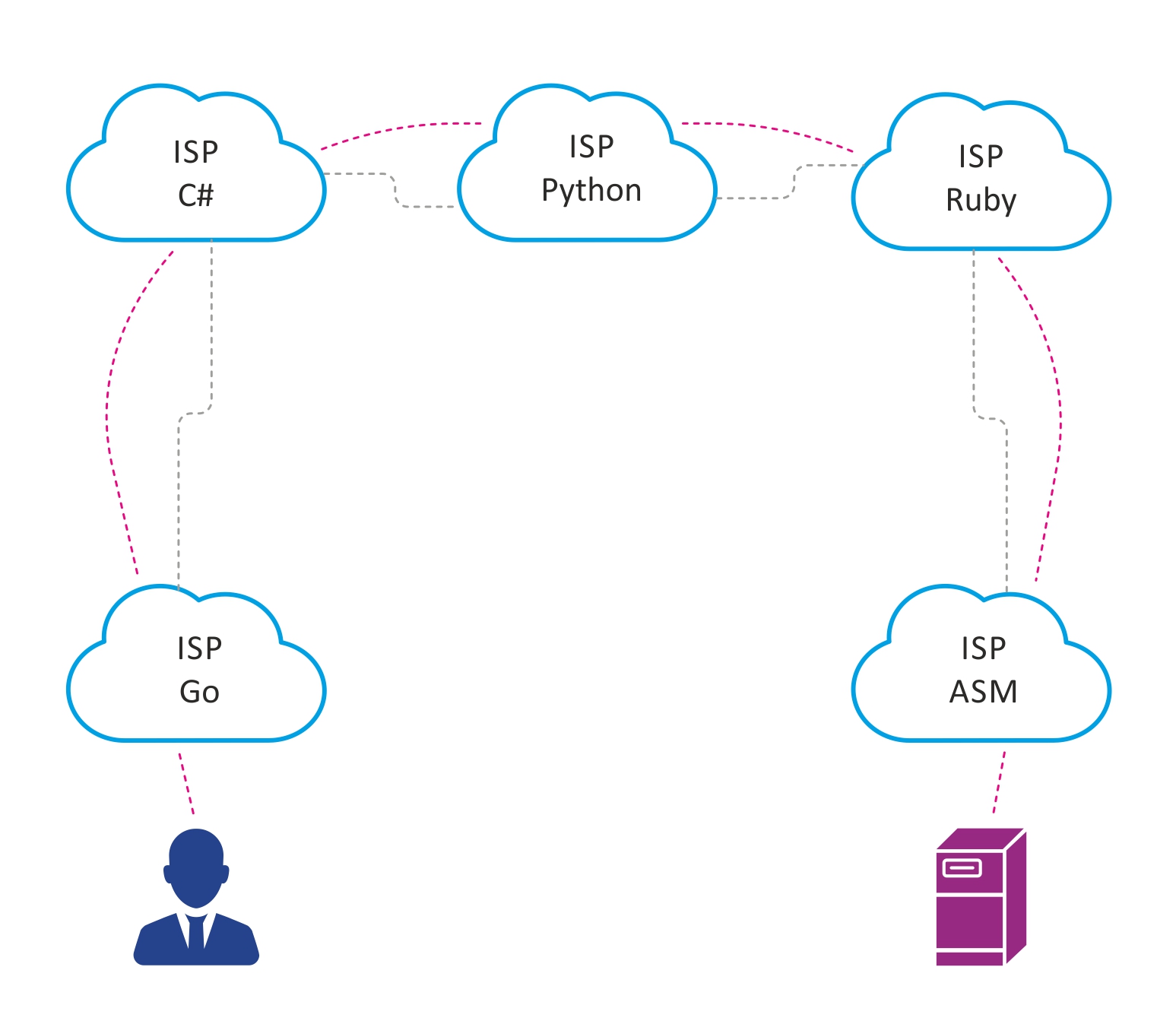
Suppose that in a large city there are 5 communication operators, peering between which, for one reason or another, is organized as shown above.
If the user Petya, connected to the Internet provider Go, wants to access the server connected to the ASM provider, then the traffic between them will be forced to go through 5 autonomous systems. This increases the delay, because increasing the number of network devices through which traffic will go, as well as the amount of transit traffic on autonomous systems between Go and ASM.How to reduce the number of transit ASs that are forced to pass traffic? That's right - a traffic exchange point.
Nowadays, the emergence of new IXPs is due to the same needs as in the early 90s-2000s, only on a smaller scale, in response to the increasing number of telecom operators, users and traffic, the growing amount of content generated by CDN networks and data centers.
What is a traffic exchange point?
A traffic exchange point is a place with a special network infrastructure where participants interested in mutual traffic exchange organize mutual peering. The main participants in the points of traffic exchange: telecom operators, Internet providers, content providers and data centers. At traffic exchange points, participants connect directly to each other. This allows you to solve the following problems:
- reduce the delay
- reduce the amount of transit traffic,
- Optimize routing between ASs.
Considering that IXPs are present in many large cities of the world, this all favorably affects the Internet as a whole.
If the situation described above with Petya is solved with the help of IXP, then it will turn out something like this:

How is the traffic exchange point arranged?
As a rule, IXP is a separate AS with its block of public IPv4 / IPv6 addresses.
The IXP network most often is a continuous L2 domain. Sometimes it’s just a VLAN that hosts all IXP clients. When it comes to larger, geographically distributed IXPs, technologies such as MPLS, VXLAN, etc. can be used to organize the L2 domain.
IXP Elements
- SCS. There is nothing unusual here: racks, optical cross-countries, patch panels.
- Switches are the foundation of IXP. The switch port is the IXP network entry point. The switches also perform some of the security functions - filter out junk traffic that should not be present on the IXP network. As a rule, switches are selected based on functional requirements - reliability, supported port speed, security features, sFlow support, etc.
- Route server (RS) is an integral and necessary part of any modern traffic exchange point. The principle of operation is very similar to the route reflector in iBGP or designated router in OSPF and solves the same problems. As the number of participants in a traffic exchange point grows, the number of BGP sessions increases, which each participant needs to support, i.e. this resembles the classic full-mesh topology in iBGP. RS solves the problem as follows: establishes a BGP session with each interested IXP participant, and he becomes a client of RS. Accepting a BGP update from one of its clients, RS sends this update to all its other clients, of course, except for the one from which this update was received. Thus, RS eliminates the need to install full-mesh between all IXP participants and elegantly solves the scalability problem. It is worth noting that the route server transparently transfers routes from one AS to another, without making changes to the transmitted BGP attributes, for example, does not add a number in its AS to the AS-path. Also, basic route filtering takes place on RS: for example, RS does not accept martians networks and IXP prefixes.
An open source software router, BIRD (bird internet routing daemon), is often used as a route server solution. It is good because it is free, quickly deployed on most linux distributions, has a flexible mechanism for configuring routing / filtering policies, and is not demanding on computing resources. Also, the hardware / virtual router of Cisco, Juniper, etc. can be selected as RS. - Security. Since the IXP network is a concentration of a large number of ASs, the security policy that all participants must follow must be well defined. As a rule, all the same mechanisms that are used to establish a BGP neighborhood between two separate BGP peers outside of IXP are applied here, as well as some additional security features.
For example, it is good practice to only allow traffic from a specific IXP mac address, which is negotiated in advance. Deny traffic with ethertype fields other than 0x0800 (IPv4), 0x08dd (IPv6), 0x0806 (ARP); this is done in order to filter out traffic that has no room for BGP peering. Mechanisms such as GTSM, RPKI, etc. can also be used.
Perhaps the above are the main components of any IXP, regardless of scale. Of course, large IXPs may use additional technologies and solutions.
It happens that IXP also provides its members with additional services:
- hosted on the IXP TLD DNS server,
- Install hardware NTP servers, allowing participants to precisely synchronize time,
- provide protection against DDoS attacks, etc.
Principle of operation
We will analyze the principle of operation of a traffic exchange point using the simplest IXP modeled by EVE-NG as an example, and then consider the basic configuration of the BIRD software router. To simplify the scheme, we omit such important things as redundancy and fault tolerance.
The network topology is shown in the figure below.
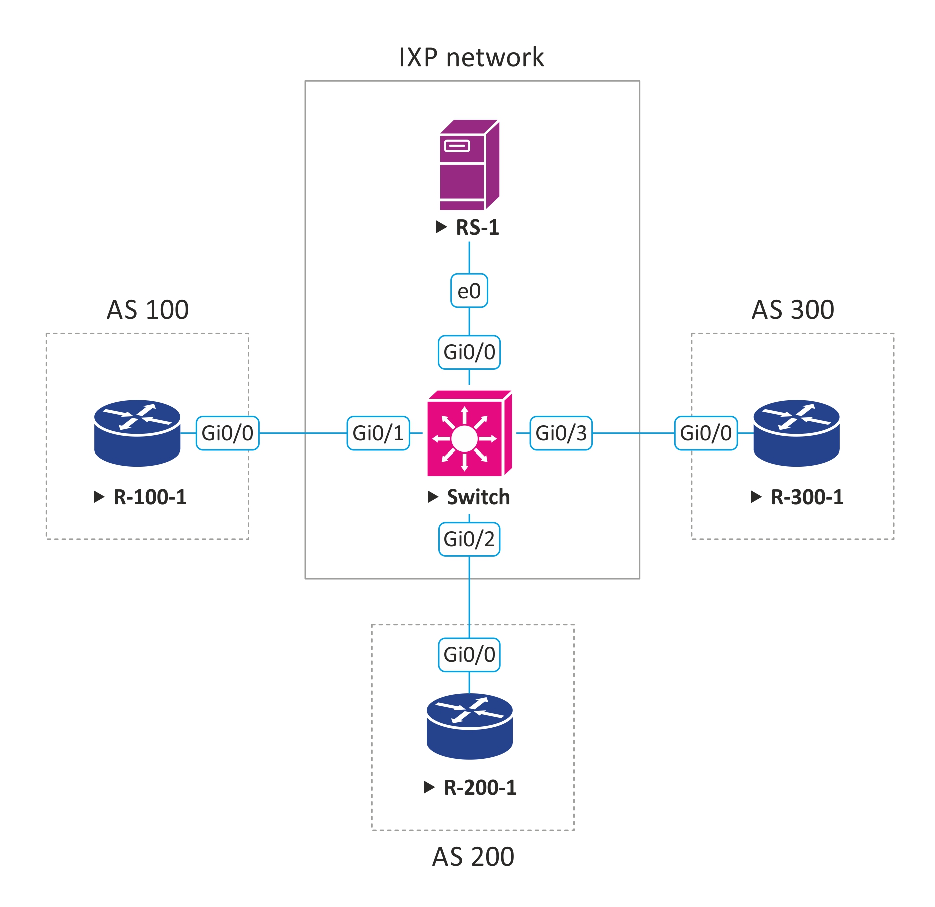
Suppose we administer a small traffic exchange point and provide the following peering options:
- public peering
- private peering
- peering via route server.
Our AS number is 555, we own an IPv4 address block - 50.50.50.0/24, from which we issue IP addresses, for those who want to connect to our network.
50.50.50.254 - IP address configured on the route server interface, with this IP clients will establish a BGP session in case of peering via RS.
Also for peering through RS, we have developed the simplest routing policy based on the BGP community, which allows IXP participants to regulate to whom and which routes to send:
| BGP community | Description |
| LOCAL_AS: PEER_AS | Pass prefixes only PEER_AS |
| LOCAL_AS: IXP_AS | Pass prefixes to all IXP members |
3 clients want to connect and exchange traffic with our IXP; let's say these are internet providers. They all want to organize peering through the route server. Below is a diagram with client connection parameters:
| Client | Customer AS Number | Customer-Announced Prefixes | ip address issued to the client to connect to IXP |
| ISP # 1 | AS 100 | 1.1.0.0/16 | 50.50.50.10/24 |
| ISP # 2 | AS 200 | 2.2.0.0/16 | 50.50.50.20/24 |
| ISP # 3 | AS 300 | 3.3.0.0/16 | 50.50.50.30/24 |
Basic BGP setup on a client router:
router bgp 100 no bgp enforce-first-as bgp log-neighbor-changes neighbor 50.50.50.254 remote-as 555 address-family ipv4 network 1.1.0.0 mask 255.255.0.0 neighbor 50.50.50.254 activate neighbor 50.50.50.254 send-community both neighbor 50.50.50.254 soft-reconfiguration inbound neighbor 50.50.50.254 route-map ixp-out out exit-address-family ip prefix-list as100-prefixes seq 5 permit 1.1.0.0/16 route-map bgp-out permit 10 match ip address prefix-list as100-prefixes set community 555:555
The setting here is no bgp enforce-first-as. By default, BGP requires that the as bgp number of the peer from which this update was received is present in the as-path of the received BGP update. But since the route server does not make changes to as-path, its number will be absent in the as-path and the update will be discarded. This setting is used to cause the router to ignore this rule.
We also see that the client installed bgp community 555: 555 on this prefix, which according to our policy means that the client wants to announce this prefix to all other participants.
For the routers of other clients, the setting will be similar, except for their unique settings.
BIRD configuration example:
define ixp_as = 555; define ixp_prefixes = [ 50.50.50.0/24+ ]; template bgp RS_CLIENT { local as ixp_as; rs client; }
The following describes a filter that does not accept martians prefixes, as well as prefixes of IXP itself:
function catch_martians_and_ixp() prefix set martians; prefix set ixp_prefixes; { martians = [ 0.0.0.0/8+, 10.0.0.0/8+, 100.64.0.0/10+, 127.0.0.0/8+, 169.254.0.0/16+, 172.16.0.0/12+, 192.0.0.0/24+, 192.0.2.0/24+, 192.168.0.0/16+, 198.18.0.0/15+, 198.51.100.0/24+, 203.0.113.0/24+, 224.0.0.0/4+, 240.0.0.0/4+ ]; if net ~ martians || net ~ ixp_prefixes then return false; return true; }
This function implements the routing policy that we described earlier.
function bgp_ixp_policy(int peer_as) { if (ixp_as, ixp_as) ~ bgp_community then return true; if (ixp_as, peer_as) ~ bgp_community then return true; return false; } filter reject_martians_and_ixp { if catch_martians_and_ixp() then reject; if ( net ~ [0.0.0.0/0{25,32} ] ) then { reject; } accept; }
We set up peering, apply appropriate filters and policies.
protocol as_100 from RS_CLIENT { neighbor 50.50.50.10 as 100; ipv4 { export where bgp_ixp_policy(100); import filter reject_martians_and_ixp; } } protocol as_200 from RS_CLIENT { neighbor 50.50.50.20 as 200; ipv4 { export where bgp_ixp_policy(200); import filter reject_martians_and_ixp; } } protocol as_300 from RS_CLIENT { neighbor 50.50.50.30 as 300; ipv4 { export where bgp_ixp_policy(300); import filter reject_martians_and_ixp; } }
It is worth noting that on the route server it’s good form to add routes from different peers to different RIBs. BIRD allows you to do this. In our example, for simplicity, all updates received from all clients are added to one common RIB.
So, let's check what we got.
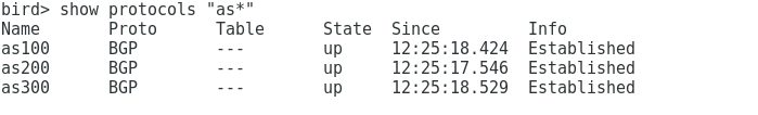
On the route server we see that with all three clients a BGP session is installed:
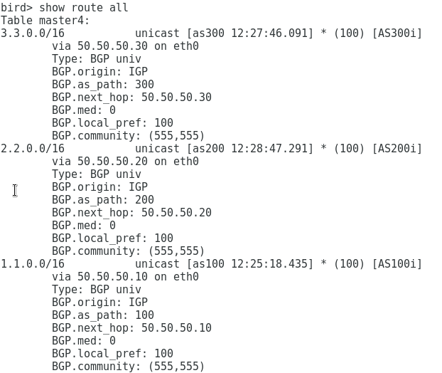
We see that we receive prefixes from all clients:
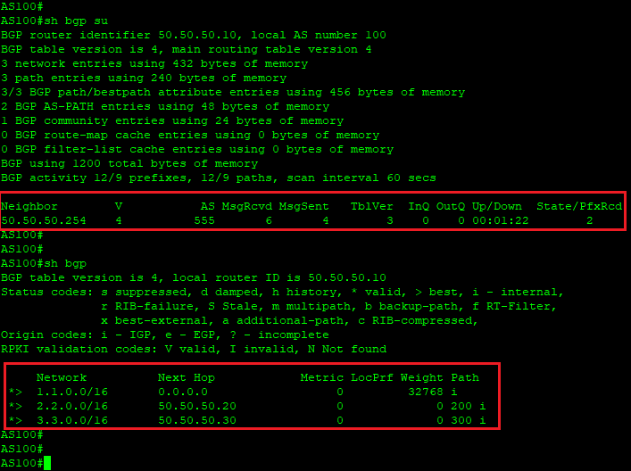
On the as 100 router, we see that if there is only one BGP session with the route server, we get prefixes from both as 200 and as 300, while the BGP attributes did not change, as if peering between the clients was carried out directly:
Thus, we see that the presence of a route server greatly simplifies the organization of peering on IXP.
I hope that this demonstration helped you better understand how traffic exchange points are arranged and how the route server on IXP is implemented.
Linxdatacenter ix
At Linxdatacenter, we built our own IXP based on a fault-tolerant infrastructure of 2 switches and 2 route servers. Now our IXP is launched in test mode, and we invite everyone to connect to Linxdatacenter IX and take part in testing. When connecting, you will be provided with a port with a bandwidth of 1 Gbit / s, the ability to peer through our route-servers, as well as access to the personal account of the IX-portal, available at ix.linxdatacenter.com .
Write in comments or private messages to gain access to testing.
Output
Traffic exchange points arose at the dawn of the Internet as a tool to address the issue of non-optimal traffic flow between telecom operators. Now with the advent of new global services and an increase in the number of CDN traffic, exchange points are also continuing to optimize the operation of the global network. An increase in the number of IXPs in the world is beneficial both for the end user of the service, and for telecom operators, content operators, etc. For IXP participants, the benefit is expressed in a reduction in the cost of organizing external peer-to-peer services, a reduction in the amount of traffic that costs higher operators, optimization of routing, and the ability to have a direct interface with content operators.
useful links
- View a map of the location of traffic exchange points: www.internetexchangemap.com
- View detailed statistics on BGP peering, including IXP presence: www.peeringdb.com