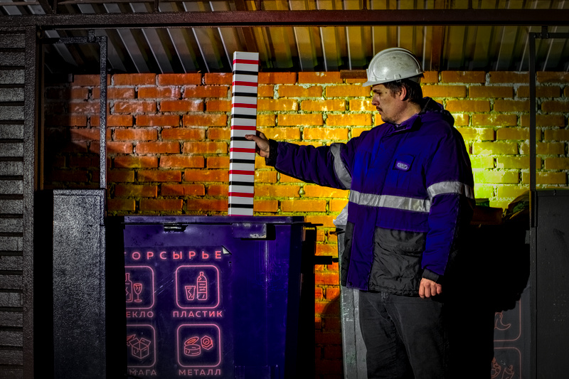
Figure 1 - Measurement of the level of fullness of the container without the use of electronic means.
I am in charge of the electronic equipment development department at the production company Big Troika LLC. The company is engaged in the automation of waste management. If you have heard anything about territorial waste management schemes and automated control systems for regional operators, there is a very high probability that we developed and implemented them. My department is small, but it is working on very interesting tasks: telematics controllers for managing a fleet of garbage trucks, various automation for landfills, container platforms and the containers themselves.
I will talk about the development of a sensor for the level of filling the container with waste . The task of such a device is to measure the amount of garbage poured into the container and transfer this data to the server for further processing. Already now, before the implementation of volume tariffing, data from such sensors can greatly help optimize the use of container sites : waste from containers should be transported within a strictly defined period of time, empty mileage of garbage trucks should be minimized, and the quantity and quality of containers on the container site should be maximally adequate to the needs of waste generators .
Ways to measure container fullness
The contents of the container, like the container itself, is not an exotic material for industrial automation. Therefore, the ways of technical solutions for measuring physical quantities are quite familiar and predictable. If you look at the instruments available on the market for determining the fullness of a container, two popular types of solutions can be distinguished: optical (infrared) and sound (ultrasound). GoodWAN products can be cited as an example of optical solutions, and Wasteout products as sound solutions . There are also microwave ovens, but it’s such an exotic thing that I’ve only heard about, but I didn’t have to see the real product at least by reference (not to mention holding it in my hands).
The level of technical complexity of these solutions also varies. For example, among the sound ones, one can find both a relatively primitive approach like “cheap Chinese parking sensors as a range finder”, and a more interesting approach to determine the geometric parameters of an unfilled volume by analyzing the response of an ultrasonic sensor to a set of pulses of different shapes. A solution that inspires respect but has a number of nuances, for example, the dependence of the obtained measurement results on the acoustic characteristics of the waste. Of the optical solutions, it was possible to meet an elegant in its simplicity determination of the level of fullness by the intersection of the rays between the receiving and transmitting parts of the sensor mounted on opposite walls of the container. Due to the fact that there are several beams, there are no problems with false sensor operation during uneven filling. Roughly, visibly, reliably, but has only two measurement results: “level above the sensor” or “level below the sensor”.
Two solutions in one
After studying existing products and a small brainstorming session, we decided to try to combine the advantages of different approaches: to obtain the predictability of the optical sensor simultaneously with the width of the measurement range and the resolution of the sound sensor. As a result, an infrared range finder GP2Y0A02YK0F from Sharp was chosen for experiments.
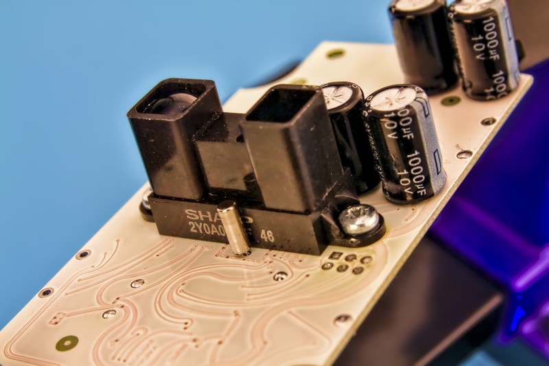
Figure 2 - Rangefinder installed on the prototype board.
The principle of operation of such a device: a focused beam illuminates the target, the beam reflected from the target returns to the sensor and illuminates the photosensitive ruler. By what cells of the line were illuminated, the reflection angle is determined, and the distance to the target is determined by the reflection angle. The measurement result is provided as an analog signal with voltage varying proportionally to the distance. All that remains for the user is to measure the magnitude of this voltage and, according to information from the documentation on the range finder, calculate the distance corresponding to the measured voltage.
Mop handle and other vulnerabilities
What are the obvious vulnerabilities when using such a sensor to measure the level of a container? There are two main ones: dirt and any narrow and long object caught in the path of the rangefinder beam, for example, a handle from a mop. The inevitable dirt on the transparent window of the sensor housing will eventually lead to diffusion of the beam and distortion of the readings. A mop handle, “successfully” placed in an empty container in the path of the beam, will cause the measurement result in the form of false fullness.

Figure 3 - Mop handle in the path of the rangefinder beam.
You can deal with these vulnerabilities using both technical and administrative methods. Using two rangefinders instead of one will allow you to avoid the “mop handle”, and regular cleaning of the transparent case window will save you from dirt. But this is all ahead. In the meantime, we use one range finder for the test version of the device in order to see in practice the adequacy of the technical solution we have chosen.
In addition to modeling ways to bypass the alleged vulnerabilities, we checked the technical limitations of the rangefinder, for example, studied the temperature drift of the output voltage. In the graph below you can see how the output voltage changes due to temperature fluctuations.
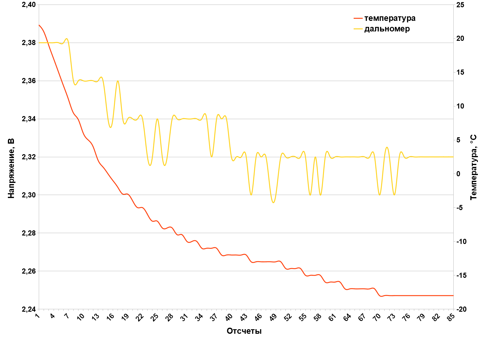
Figure 4 - Red graph - air temperature near the rangefinder; yellow graph - voltage of the range finder measuring the same distance at a changing temperature.
The range finder voltage drops with temperature, and below -12 ° C the voltage drift slows down. The voltage drop is about 50 mV, which in practice means an error of the measured distance of only ± 10 mm at distances from 200 to 500 mm. For our tasks, such accuracy is more than sufficient. Interestingly, the openly available documentation for the rangefinder does not contain information on temperature drift, but very wide tolerances for the output voltage of ± 150 mV are indicated. The manufacturer guarantees the performance of the rangefinder only up to -10 ° C. In practice, we tested these rangefinders in the laboratory and at facilities in other projects in the winter: up to -30 ° C they work stably and without consequences for the service life and accuracy of measurements.
All these nuances with the accuracy of the data obtained do not allow us to attribute the fullness sensor to measuring instruments, it is more correct to classify our device as a class of indicators. This, however, does not interfere with the task at all.
Data transfer method
Here, too, most often it all comes down to two approaches: work in cellular mobile radio networks or work in private LPWAN (energy-efficient long-range networks).

Figure 5 - SIMCom SIM800 radio module, Mobinus Tri 4 ceramic antenna and SIM card holder on the prototype board.
Work in cellular networks is good because such networks are massively deployed around the world, have an impressive percentage of coverage used for sensor placement of territories, and large companies with large financial and human resources are engaged in servicing these networks. It is enough just to conclude a competent contract with a mobile operator, having received a convenient and favorable tariff from him, and that’s all: take away SIM cards in batches, put them on your devices.
The obvious disadvantages of this approach are financial dependence on the operator (you have to include the cost of cellular communication in the tariffs for the consumer of your services, as a result, the cost of the service increases along with customer dissatisfaction) and the low energy efficiency of transmitting small amounts of data. I’ll explain more about low energy efficiency: if you need to send a dozen or two bytes of information every few hours, you need to turn on the radio module, wait for the module to register on the cellular network, and only after that send an SMS or open a connection session to the Internet. All these processes are far from instantaneous and take units (sometimes tens) of seconds. That is, for those milliseconds (or even microseconds) of operation of the radio module, for which your tens of bytes went on the air, there are tens of seconds of work spent on the overhead of servicing this transfer process! The situation is aggravated if you use radio modules that work in 2G networks (and these are still the most popular and inexpensive modules in the modern market of electronic components): in some countries, support for 2G standards is already disabled, in many others they are supported on the residual principle with low priority service. In this case, the registration time in the network increases, and sometimes the registration is refused at all, which means that the overhead costs for electricity increase again. In an attempt to find a compromise, NB-IoT was developed as one of the standards for 4G networks. It is already working, but not yet impressive: the coverage area in Russia is still smaller than that of 2G networks, although energy consumption and overhead are much less, but still not enough to justify all the risks of the transition. We really hope that with NB-IoT everything will be better in the foreseeable future, the transition to this standard will become a real salvation from dying 2G networks.
Work in LPWAN networks is almost ideal in terms of energy efficiency. But there is one big drawback - this is the infrastructure. Either you need to look for a partner who already has such a network, or raise your own. And not every company is ready to take such a step. There is cause for concern for the paranoid: such networks are much easier to “put” with malicious acts than a cellular network. And the consequences for the attacker are completely different: mobile operators, as a rule, have their own serious security services and the ability to quickly and efficiently provoke a tough and timely reaction from the competent state authorities. Most often, LPWAN network operators do not have such resources. Nevertheless, solutions for working in LPWAN networks are presented on the market, and the companies providing them are quite ready to deploy their networks at client facilities.
So far, we have decided for ourselves to choose an ineffective in energy consumption, but a proven method - data transfer via SMS-messages in 2G networks. But towards NB-IoT we look eagerly and intently!
Batteries
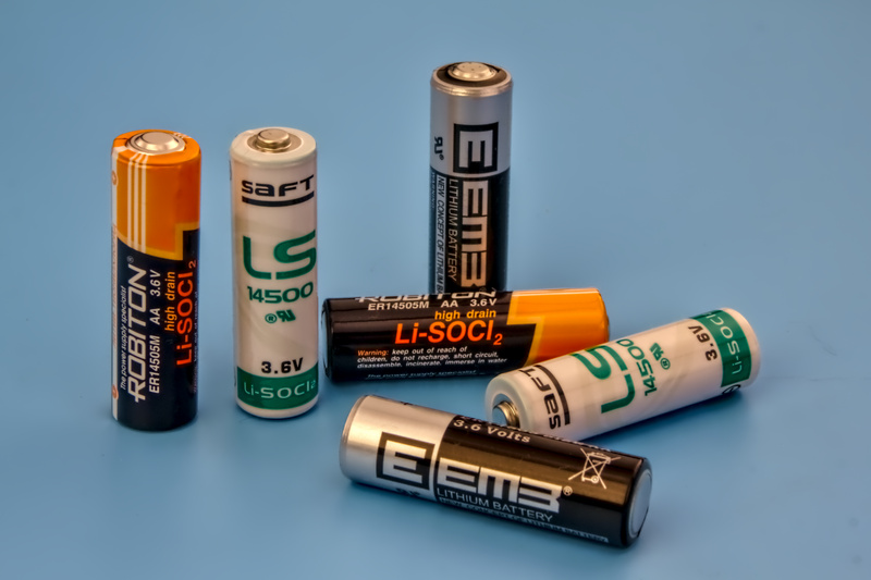
Figure 6 - Lithium thionyl chloride AA batteries of different manufacturers.
If you need a long service life, low self-discharge current, high specific capacity and a wide range of operating temperatures, then there is only one choice - lithium-thionyl chloride batteries (Li-SOCl2). Their charm is that they provide all of the above characteristics at the same time! However, you have to pay for everything, and in the case of Li-SOCl2 “batteries” both literally (their prices are relatively high) and figuratively. The fact is that these elements have a very high internal resistance (when compared with batteries with similar mass and size characteristics, with another “chemistry”). In addition, a passivation film is formed on the surface of the electrodes of these elements, which further increases the internal resistance. Manufacturers specifically describe the depassivation procedure in the documentation for the elements: before starting operation, you need to load the element with a certain current for a certain time.
What is bad about the high internal resistance of a battery? Inability to give high current. And those peak 2 A, which manufacturers request for 2G radio modules, for such elements is such a high current that makes the operation of these modules with a direct connection to a lithium-thionyl chloride element almost impossible. Saves only the use of relatively large and expensive Li-SOCl2 elements of size C (and larger), and even then in a special “high-current” version (differs from the “ordinary” version in the way of winding the electrodes). Well, the installation of capacities is larger in the power circuit of the radio module, but with low parasitic resistance and inductance.
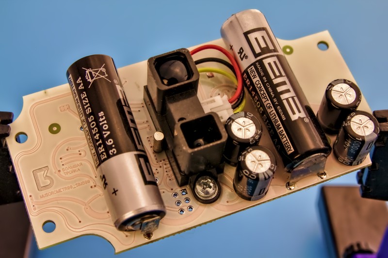
Figure 7 - Two Li-SOCl2 cells ER14505 from EEMB, installed on the prototype board.
We were somewhat confused by the cost and dimensions of elements of frame size C, and we found a different approach - the use of two series-connected elements of frame size AA and a step-down pulse converter. In this case, for the stable operation of the radio module for enough time to send an SMS message, two “high-current” elements are enough, and when certain tricks and restrictions are introduced into the power management algorithms, even “ordinary” Li-SOCl2 elements of size AA! Bench tests showed: two series-connected elements demonstrate the ratio of the number of communication outputs of the radio module to the total capacity of the elements better than a single element of frame size C, and slightly worse than a single “high-current” element of frame size C. A very decent result.
Assembly of prototypes and bench tests
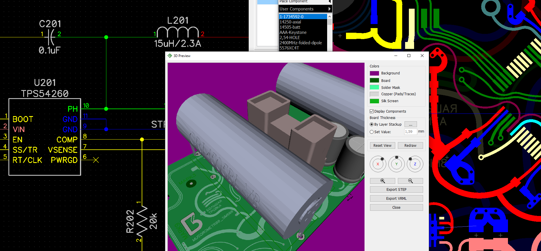
Figure 8 - Development of the circuit and printed circuit board in the DipTrace software package.
After we decided on the key elements of the future device, the process went along the thumb track. I developed a circuit diagram and a printed circuit board, our installer-installer “sprayed” a layer of components on the boards obtained from the production. After that, the boards fell into the hands of the microcontroller programmer, who began to breathe life in the form of test firmware into new devices.
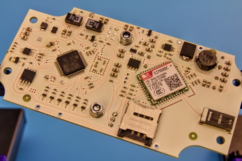
Figure 9 - The prototype circuit board with components installed on it.
The main task of the test firmware is to help quickly accumulate failure statistics of the radio module and provide enough data with real measurement results from rangefinders. A small meeting room was perfect for installing the prototype in an office environment: the device was mounted on a wall and sent by a range finder to a door that employees open and close many times a day.
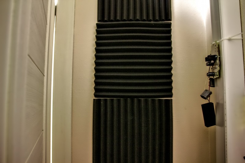
Figure 10 - The prototype board with a hanging battery holder (right) is directed to the ajar door (left).
After switching on, the device began to send SMS messages in a human-readable format with important information for us: the supply voltage for small and heavy loads, an array of measurements from rangefinders, the air temperature around the device board and a pair of meters. One counter counts the number of times the radio is turned on, and the other counts the number of messages sent. According to these two counters, one can immediately see how many times the radio module encountered network registration problems (before reaching the stage of sending messages) and how many messages were sent. Through numbering of messages allows you to visually identify missed SMS. The temperature sensor, by the way, has another important function - if you are lucky, the device will have time to detect a fire in the container and send an extraordinary message with an alarm.

Figure 11 - Messages from the prototype on the smartphone screen.
The first results of the test tests showed several minor flaws in the circuitry: a lack of capacity in the power supply circuits of the controller could in some cases lead to a reboot when the power switch of the radio module was turned on. We easily fixed this by adding an additional capacitor to the prototype boards. If we recall the relatively high internal resistance of the batteries, then we can understand why the inclusion of a radio module is such a big event for the device. Just look at the voltage fluctuations in the circuits on the oscilloscope screen before installing additional capacitors in the controller power circuit.
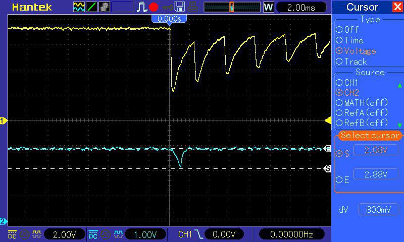
Figure 12 - Yellow graph - voltage on the batteries; turquoise - voltage in the power supply circuit of the controller.
After correction, everything is much more decent: a sharp voltage drop in the controller’s power supply circuit is not observed.

Figure 13 - Yellow graph - voltage on the batteries; turquoise - voltage in the power supply circuit of the controller. The drawdown on the turquoise chart disappeared after installing an additional capacitor.
By the way, the “saw” on the graph of the voltage of the batteries is not a bug, it is a feature: the input capacities of the voltage converter are charged with short pulses to stretch the front of the surge of the charging current. With power in devices with great autonomy and powered by chemical current sources, there are a lot of problems. For example, you can’t put any capacitors on duty circuits: you need to select models with low leakage currents. All rarely used, which can gradually “etch” the current, you have to put tightly closed keys. Well, about the "restless legs syndrome" on Habré there is already a wonderful article .
It’s not just the supply chain that is causing concern. The interaction of the radio module with the cellular network is a separate detective story. Refusals to register on the network, refusals to provide services, and unpredictable time delays between the various stages of working with data transfer are commonplace that many users of GSM radio modules have faced. And in conditions of unstable communication quality, we do not have enough working time to send SMS messages. It looks like this: with some attempt, the radio module nevertheless breaks through the air and receives registration on the network. After this, unsuccessful attempts to send a message follow until the time allotted for the continuous operation of the radio module comes out. Thus, precious attempts to get in touch are lost, and a simple increase in the maximum time of continuous operation is dangerous: there is a possibility of greatly increasing the internal resistance of batteries with subsequent long-term restoration. In the graph below you can observe the process of growth in the number of different data transmission errors.
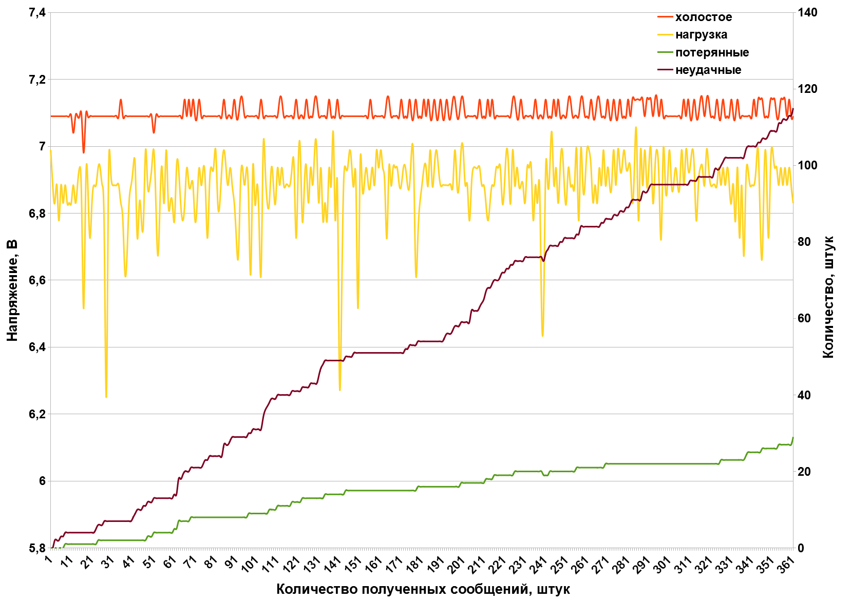
Figure 14 - Red graph - voltage of batteries without load; yellow - voltage of the batteries under load during operation of the radio module; green graph - the difference between the number of successful registrations of the radio module and the number of received messages; purple - the difference between the number of turns on the radio module and the number of received messages.
Statistical data in the form of a table:
| The average supply voltage without load, V | 7,096 |
| Maximum voltage under load, V | 7,041 |
| Minimum supply voltage under load, V | 6,253 |
| The number of turns on the radio module, pieces | 476 |
| The number of verified registrations in the network, pieces | 390 |
| The number of messages received by the addressee, pieces | 361 |
This is already an alarming bell: improving the quality of services and expanding the coverage area for 2G networks is not expected. While we will deal with this phenomenon algorithmically: we will dynamically change the maximum time of continuous operation and at the same time monitor the degree of subsidence of the voltage of the elements under load. Well, if you spent precious electricity from the batteries to turn on the radio module, you need to make every effort depending on us to make sure that this energy was not wasted.
As for the data from the rangefinder, everything is predictable and stable there. The graphs clearly show when the door to the meeting room is open, and when it is closed.
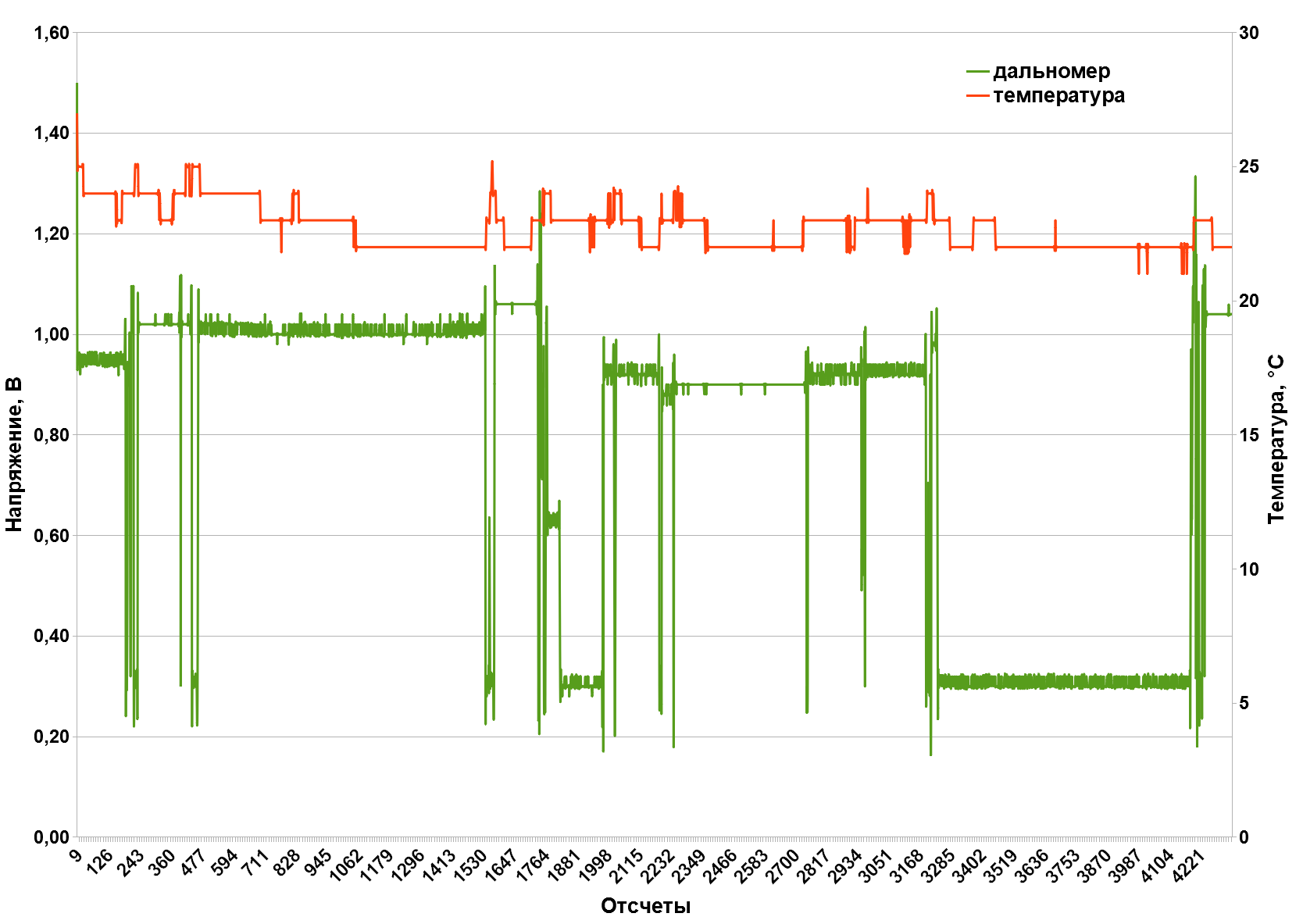
Figure 15 - Green graph - voltage at the output of the range finder; red graph - temperature from the sensor on the board.
Future plans
After conducting bench tests and correcting the shortcomings found, we prepared a couple of devices for installation at the customer’s site. With hull products, the popular Gainta came to the rescue. Soon the devices will be installed in real containers, and we will finally move from bench testing to trial operation.
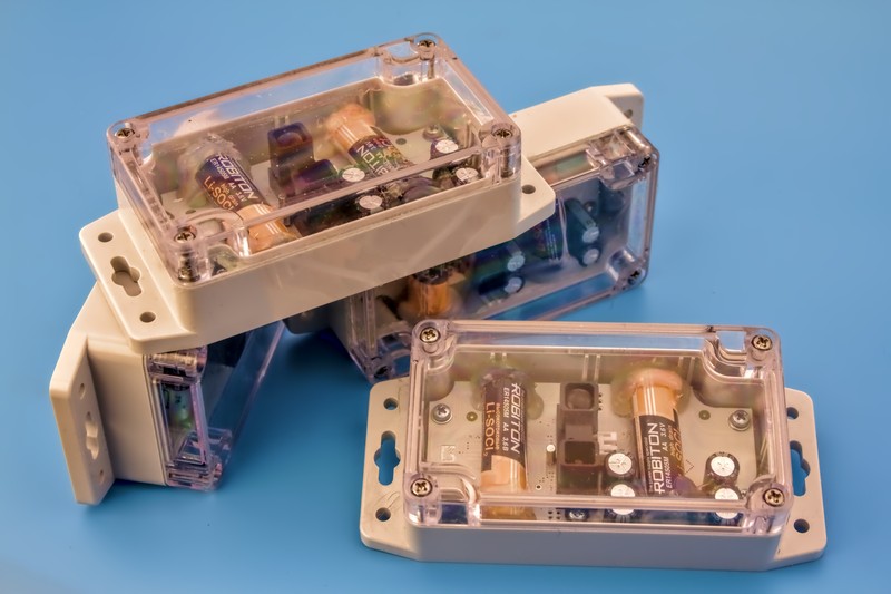
Figure 16 - Experimental instances of the device assembled, tested and ready for installation on customer sites.
Even at the development stage, we began to accumulate ideas for improving the device. Minor changes in circuitry - this is understandable, add capacities there, then reduce, change denominations and the like routine. And of the larger and more obvious innovations, the following can be distinguished:
- Transition from Sharp rangefinders to the more compact rangefinders of the VL53Lxx series from STMicroelectronics. Compactness is not their only plus: they are connected via a digital interface, they have a configurable two-dimensional receiving matrix, more affordable for purchase in Russia.
- Adding a MEMS accelerometer. A component quite common among similar devices that allows you to determine the spatial position of the sensor (and the mechanically connected container or its lid). It generally turned out strange with the accelerometer: for some reason, it did not migrate to the circuit diagram of the prototype from our other devices, where it was regularly used. It happens. I will be corrected.
- The long-awaited transition to the use of NB-IoT-radio modules.
- The transition from purchased standard cases to something more original and structurally suitable for our task.
- Implementation of own short-range radio network for the joint operation of container full sensors and telematics controllers in garbage trucks.

Figure 17 - Prototype device assembly.
That's all for now! I hope it was interesting. As I progress in testing and development, I will write sequels to this article.