
Writing algorithms is probably the most interesting part for me in home automation. But even the whole mass of sensors and scripts can’t cope with the exuberant imagination of life and you have to add a method of direct control. As manual controls, you can put an ordinary doorbell, but what if you want more? We meet the hero of this article - a gesture sensor based on SI1143 from Silicon Labs.
SI1143 itself:
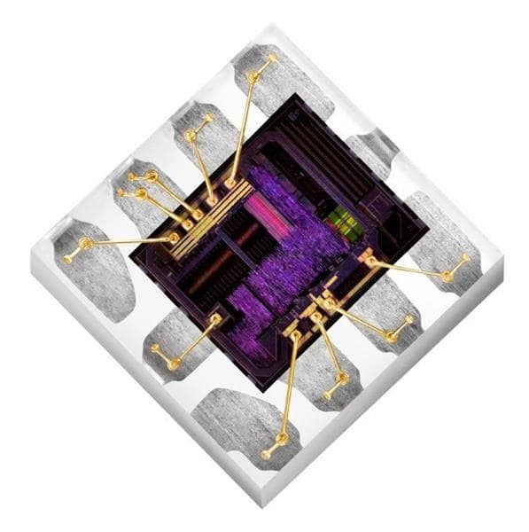
It really looks futuristic.
And how many advantages:
- highly sensitive photodiode, low noise ADC
- LED drivers with currents from 6 to 360 milliamps
- powered from 1.71 to 3.6 volts
- and smart I2C - up to 3.4 megabits per second
That's just the size pumped up only 5 by 3 millimeters. This is not the first time you see it. Well, here you need a little more strapping.
Can this be removed? My feeling of beauty asked. Then I will try to satisfy the request of this rare guest in our area and hide the board in the building. In the meantime, you can apply power and see what happened.
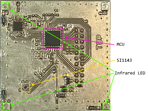
Comment for the attentive. There really are a few more details than expected. The node from the Enviriot project was taken as the basis. In addition to the STM32F051 microcontroller, the board also has an 868 megahertz CC1101 transceiver from Texas Instruments and after filling in the firmware, it is enough to supply power and the device will connect to the MQTT-SN server.
The principle of operation is based on measuring the level of the reflected signal from each of the 3 LEDs. I'll try to turn it on and look at the response.
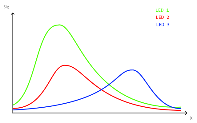
Due to the asymmetric arrangement of the LEDs, the signal from LED 1 is noticeably larger and you will have to normalize the measurement results first.
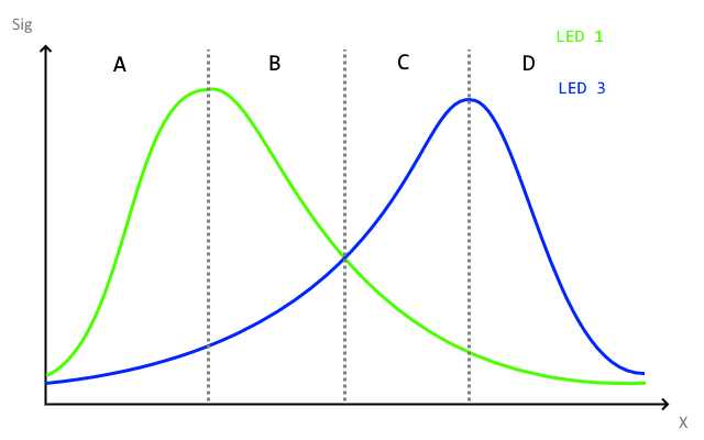
And so the dependence is already quite understandable. I'll try to code the following algorithm:
| A | B | C | D | |
|---|---|---|---|---|
| ===>
| L1 +
L3 + L1> L3 | L1-
L3 + L1> L3 | L1-
L3 + L1> L3 | L1-
L3- L1 <L3 |
| <===
| L1-
L3- L1 <L3 | L1 +
L3- L1 <L3 | L1 +
L3- L1 <L3 | L1 +
L3 + L1> L3 |
Where L1 + - the signal from LED 1 increases, L1> L3 - the signal from LED 1 is greater than the signal from LED 3.
It was smooth on paper, but in the dynamics problems started. For a sheet of white paper fixed at the same height, the expected results were obtained in two cases out of three. When I try to wave my hands, the signal starts to jump and my wonderful algorithm began to get confused in the readings. I looked at my hand, but there are many differences from a flat sheet of white paper. But somehow it should work. Okay. Persuaded! I will try to read the documentation.
For the afflicted, Silicon Labs has released AppNote AN580 - “INFRARED GESTURE SENSING”. 2 basic methods for determining gestures and their possible combinations are described. The first method is to determine the position at each moment in time and to determine gestures based on the coordinates. The second method determines the phase shift between the signals. One of the variants of the first method has already been tested and it was not impressive. I will try to implement the second.
Go. It is necessary to implement as many as two points. Determine the moment of entry and transfer this data to the state machine. The input threshold was determined experimentally at 1/8 of the total signal. To protect against noise, I will add the Schmidt trigger, turn on by 15% and turn off by 10%.
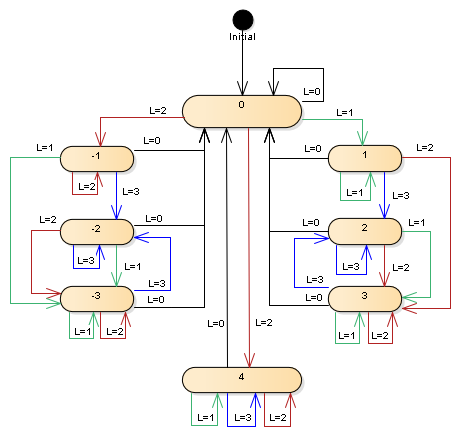
Well, the state machine itself. States 1 to 3 - upward movement, states -1 to -3 - downward movement and state 4 for the unlikely event that both LEDs work simultaneously.
Now let's try to take off with all this.
var LSt = new Int8Array([-3, -3, -3, 1, 1, 3, 3, 4, -3, -3, -1, -1, 3, 3, 3, 4, -2, -2, -2, 4, 2, 2, 2, 4]); /* ...... */ this.r1 = false; this.r3 = false; this.button = new Int8(0); /* ...... */ if(n1 > 15) { this.r1 = true; } else if(n1 < 10) { this.r1 = false; } if(n3 > 15) { this.r3 = true; } else if(n3 < 10) { this.r3 = false; } let st = (this.r1?1:0) | (this.r3?2:0); if(st == 0){ // . this.button = 0; } else { this.button = LSt[st*8 + this.button - 5]; }
The variables n1 and n3 contain normalized values for the corresponding LEDs. The result is in the button field.
For further use, states 2 - up and -2 - down are useful.
The program is written in a subset of JavaScript, then compiled into bytecode and uploaded to the device. JavaScript is parsed and AST is generated by the NiL.JS library from comrade IaIojek , for which many thanks to him.
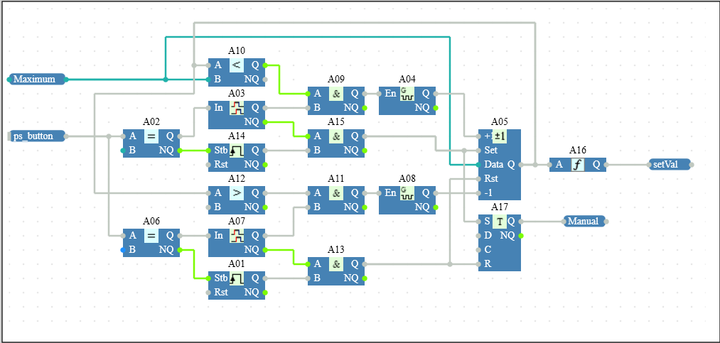
If state 2 lasts less than 0.3 seconds, the A14 and A15 blocks are responsible for this, the brightness is set to the maximum. Blocks A01 and A13 set the brightness to 0 for a short downward movement.
When moving up and holding blocks A10, A09 and A04 provide a smooth increase in brightness. When moving down and holding, blocks A12, A11 and A08 work and allow to reduce the level.
Demonstration of work. 20 megabytes GIF. 
Well, perhaps that's all. The customer is happy, and I'm starting to think about the next version. Of the necessary changes: place the LEDs at the same distance from the receiver, display the operation indication and do a poll on a separate controller, which will reduce the polling interval.