From the comments on the articles, I noticed that some readers believe that Redd and FPGA are like Lenin and the Party. That they are inextricably linked. In fact, this is not so at all. I just wanted to start a conversation about the Redd complex with something interesting, but what could be more interesting than FPGA? Well, and starting a conversation, interrupting at a glance is stupid. And finally, the big logical block is complete. And to show that FPGAs are far from the whole of Redd, I propose to make approximately three articles about things not related to them. Well, and having completed this block, already go to FPGA practice.

Introduction
The most amazing thing is that as soon as I decided to make a digression on other topics, the good bosses threw me into a difficult battle on a project where work is in progress with the VHDL language and Xilinx FPGA. Firstly, that is why for a long time I did not pick up a pen in general, and secondly, it is clear that the preparation of practical articles requires a large number of experiments. It is somewhat difficult to deal with VHDL / Verilog and Xilinx / Altera at the same time. So a break in the stories about FPGAs would have to be done anyway.
So. In the first article of the series, we already examined the structural diagram of the Redd complex. Let's do it one more time.

In today's article, Linux experts are unlikely to find much valuable information, but it’s worthwhile to go over the pictures superficially. Those who, like me, are used to working from the Windows OS, will find a list of ready-made techniques that allow you to work with the complex. In general, this article will bring the skills of those and other groups of readers to a common denominator.
Previous cycle articles
- Development of the simplest “firmware” for FPGAs installed in Redd, and debugging using the memory test as an example.
- Development of the simplest “firmware” for FPGAs installed in Redd. Part 2. Program code.
- Development of its own core for embedding in a FPGA-based processor system.
- Development of programs for the central processor Redd on the example of access to the FPGA.
- The first experiments using the streaming protocol on the example of the CPU and processor communication in the FPGA of the Redd complex.
- Merry Quartusel, or how the processor has come to such a life.
- Code Optimization Methods for Redd. Part 1: cache effect.
- Code Optimization Methods for Redd. Part 2: non-cached memory and parallel bus operation.
- Extensive code optimization: replacing a clock generator to improve system performance.
UART Blocks (Serial Ports)
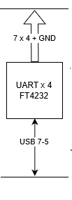
In the block diagram, we see the FT4232 controller that implements 4 serial ports (UART):
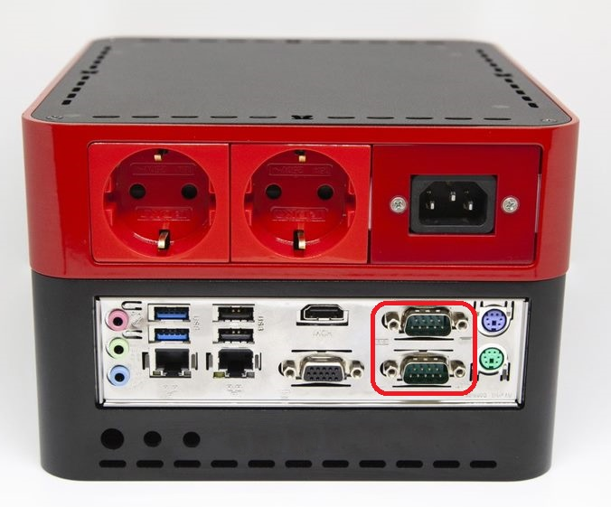
But if you talk a little more globally, then the Redd complex has not four, but six serial ports. Just the four mentioned above have CMOS levels, and two more are soldered to the motherboard, because the complex is based on an ordinary PC.

Accordingly, they have levels - RS232 (plus or minus 12 volts). RS232 ports - everything is clear with them, they are displayed in the form of two standard DB-9 connectors,
and where to look for lines with CMOS levels? In general - on a common connector. Its pinout is shown in the electrical circuit diagram. There are, among other things, contacts corresponding to UART.

Externally, this connector looks as follows:

How to use it depends on the task. You can make a harness to connect each device. This approach is useful if someone uses the Redd complex to test periodically manufactured devices of the same kind. But the main purpose of the complex is still debugging the equipment being developed. And in this case, it’s easier to connect to it in a temporary fashion. This temporary pattern is visible on screensavers for all articles: Aruino wires are inserted directly into the connector. Of course, counting contacts is still a pleasure, and if they accidentally fly out, it is so difficult to restore switching that it is easier to reconnect everything from scratch; therefore, to facilitate life, there is a riser board to which you can connect at least using two-row connectors, at least with the same Arduino wiring.

UART Software Access
The serial port is a well-established, well-standardized element, therefore, work with it does not go through some specific FTDI libraries, but through standard means. Let's look at how these tools look on Linux.
Port names
From a number of articles and forums on the network, it follows that the port names provided by USB-Serial adapters are in the format / dev / ttyUSB0, / dev / ttyUSB1, and so on. In Linux, all devices can be viewed using the same commands as for viewing ordinary directories (in fact, devices are the same files). Let's see what names are in our system. We give the command:
ls / dev /

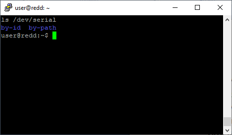
The names that interest us are highlighted in red. Something a lot of them. Which port corresponds to what? Those who are well versed in Linux know thousands of spells for all occasions. But for those who still worked with Windows 3.1 (well, in parallel with the then quite peppy old lady RT-11), it’s still difficult to remember, with age the new one is more difficult to remember. Therefore, it is easier to find everything every time, using simple ways. And I highlighted the entrance to this simple path with a green frame. Conditional subdirectory serial. Now we are looking at the / dev / namespace. And let's see the space / dev / serial :
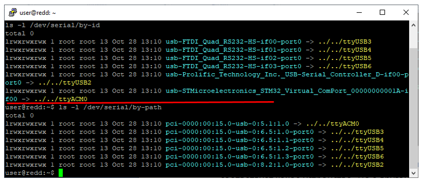
Fine! We delve into the hierarchy, look at the space / dev / serial / by-id . Just looking ahead, I’ll say that for the correct display you need to use the ls command with the –l switch (thanks to my boss for the clarification). That is, we give the command:
ls –l / dev / serial / by-id
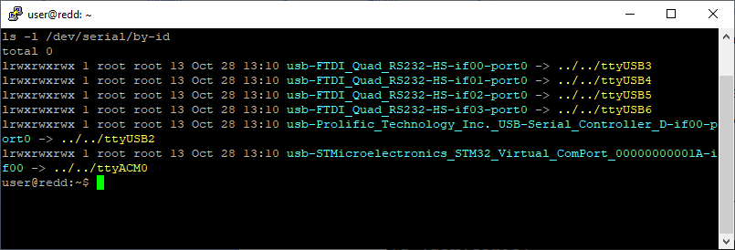
On the one hand, everything is fine. Now we know which names in the space / dev / ttyUSBX correspond to which device. In particular, ports organized by the FT4232 (Quad) bridge have names from ttyUSB3 to ttyUSB6 . But on the other hand, when considering this site, I realized that in Paris in the chamber of weights and measures there must necessarily be a room in which the standard of the mess is placed ... Because somehow you need to be able to measure its value. Well, let's say the lack of ports / dev / ttyUSB0 and / dev / ttyUSB1 can be easily explained. But how to explain that the “native” ports based on the offspring of the installed FTDI bridge are numbered from the top three, and the third-party Prolific controller, inserted for a specific project, took port number 2? How can one work in such an environment? Tomorrow someone will plug another controller into the complex (since the complex allows different groups of developers to work with different equipment at the same time), and the ports move out again. What ports should be assigned to us in the configuration file for a working application?
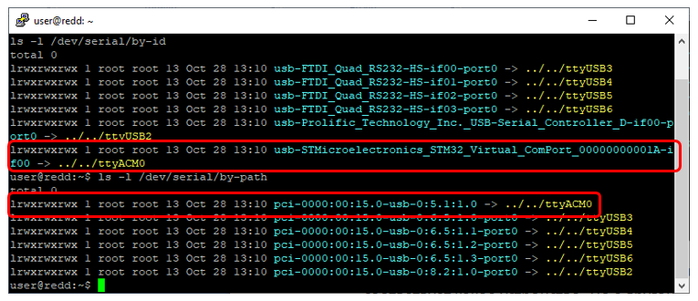
It turns out that everything is not so bad. Firstly, the yellow name / dev / ttyUSB3 and the blue name / dev / serial / by-id / usb-FTDI_Quad_RS232-HS-if00-port0 are two aliases of the same device. And the second option can also be presented as the port name, but it is already more permanent than the first. True, in this case, everything is somewhat bad. An external controller based on FT4232 can be plugged into the complex, and it will already be necessary to deal with their numbering. And here "secondly" comes to our aid. Namely, another alternative naming convention. We remember that the / dev / serial directory contained not only the / by-id subdirectory, but also the / by-path subdirectory. We check its contents (it is located at the bottom of the next figure, under a red line).
Everything here is tied to physical architecture. And I have already said many times that all the controllers inside the complex are soldered to the boards, so the internal hierarchy will not change. Thus, the name /dev/serial/by-path/pci-0000:00:15.0-usb-0:6.5:1.0-port0 will be the hardest.
In total, we have the following way to search for the port name (it should be done once, the results for your instance of the complex can be put into the table and used constantly):
- Issue the command ls –l / dev / serial / by-id .
- Issue the ls –l / dev / serial / by-path command .
- From the results of point 1, find the port name corresponding to the required port of the required bridge. Find the same port name in the results of paragraph 2. Take the physical name corresponding to this paragraph.
For the ports served by the controller on the motherboard, everything is a little more complicated. Here you can’t make the way from the simplest command “ ls / dev ”, but you have to remember something (well, or at least remember that for help you can contact here). Everywhere it says that the typical port names are ttyS0-ttyS3 . The question remains, on what names are the real ports in our system? I found the following spell answering this question:
ls / sys / class / tty / * / device / driver
Here is the system response to it:
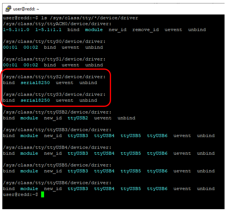
It turns out that we need to use the names / dev / ttyS2 and / dev / ttyS3 . Why i do not know. But one thing pleases: here no special changes are foreseen, therefore these constants can be remembered and used without fear that they will change.
Code development
When developing, you should use the wonderful Serial Programming Guide for POSIX Operating Systems (the first direct link you get is https://www.cmrr.umn.edu/~strupp/serial.html , but nobody knows how long it will live). It is especially important that it tells how to work with a full set of signals, because the ports in the complex are fully implemented. True, today we will use only the Tx and Rx lines.
Usually I give the results of the oscillogram, but now it turns out that I am in almost real conditions: the complex is located where my hands cannot reach, so I can’t connect the oscilloscope probe. To see at least some result, at my request, colleagues added a couple of postings to the complex according to the following classical scheme:

Let's try to transfer from one port to another. In our case, the ports /dev/serial/by-path/pci-0000:00:15.0-usb-0:6.5:1.2-port0 and /dev/serial/by-path/pci-0000:00:15.0- are connected usb-0: 6.5: 1.3-port0 .
We already discussed how programs for the Redd central processor are written in one of the previous articles , so today we will restrict ourselves to just the program text, written under the impression of the Serial Programming Guide for POSIX Operating Systems . Actually, the main interesting point there is switching the reception strategy to non-blocking reading, the rest is trivial. Nevertheless, given the mess in the examples on the network on this topic, it’s better to still have a trivial sample on hand (it will be shown later that even an example based on this wonderful document didn’t work 100%, the code below differs from the canons described in it in one line, but more on that below).
The same sample code
#include <cstdio> #include <unistd.h> /* UNIX standard function definitions */ #include <fcntl.h> /* File control definitions */ #include <errno.h> /* Error number definitions */ #include <termios.h> /* POSIX terminal control definitions */ int OpenUART(const char* portName, speed_t baudRate) { // int fd = open(portName, O_RDWR | O_NOCTTY | O_NDELAY); // if (fd == -1) { return fd; } // fcntl(fd, F_SETFL, FNDELAY); // termios options; tcgetattr(fd, &options); // , // , . ... cfsetspeed(&options, baudRate); // ... // 1 , , 8 options.c_cflag &= ~PARENB; options.c_cflag &= ~CSTOPB; options.c_cflag &= ~CSIZE; options.c_cflag |= CS8; options.c_cflag |= (CLOCAL | CREAD); // , ... tcsetattr(fd, TCSANOW, &options); return fd; } int main() { printf("hello from ReddUARTTest!\n"); int fd1 = OpenUART("/dev/serial/by-path/pci-0000:00:15.0-usb-0:6.5:1.3-port0", 9600); int fd2 = OpenUART("/dev/serial/by-path/pci-0000:00:15.0-usb-0:6.5:1.2-port0", 9600); if ((fd1 != -1) && (fd2 != -1)) { static const unsigned char dataForSend[] = {0xff,0xfe,0xfd,0xfb}; // write(fd1, dataForSend, sizeof(dataForSend)); unsigned char dataForReceive[128]; ssize_t cnt = 0; // , , // int readSteps = 0; // , while (cnt < (ssize_t)sizeof(dataForSend)) { readSteps += 1; ssize_t rd = read(fd2, dataForReceive + cnt, sizeof(dataForReceive) - cnt); // - , if (rd <= 0) { usleep(1000); } else // - { cnt += rd; } } // printf("%d read operations\n", readSteps); printf("Read Data: "); for (unsigned int i = 0; i < cnt; i++) { printf("%X ", dataForReceive[i]); } printf("\n"); } else { printf("Error with any port open!\n"); } // if (fd1 != -1) { close(fd1); } if (fd2 != -1) { close(fd2); } return 0; }
Run - get the predicted result:
hello from ReddUARTTest! 14 read operations Read Data: FF FE FD FB
It can be seen that 4 bytes took up 14 attempts, that is, the reading was not blocking. Sometimes the system returned a “no new data” state, and the program went to sleep for one millisecond.
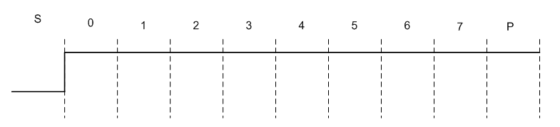
In general, everything is fine, but without an oscilloscope I can’t be sure that two ports based on the same chip really set the speed. I already jumped on the fact that the speed was the same (for that he had one controller), but not the one I ordered. Let's at least somehow check that it is at least controlled. To do this, I will set the speed of the receiving port to twice that of the transmitting port. And knowing the physics of the data transfer process, you can predict how these data will be distorted during reception. Let's look at the transfer of the 0xff byte in graphical form. S - start bit (there is always zero) bit, P - stop bit (there is always one), 0-7 - data bits (for the constant 0xFF - all units).
And now let’s put on this figure a view of how everything will be viewed by a receiver operating at twice the speed:

Perfectly. The value "1111 1110" should be accepted (the data goes the least significant bit forward), that is, 0xFE. The second half of the transmitted value does not affect reception, since units correspond to silence in the line. That is, we transmitted one byte, one byte will also come.
We will build the same graph for verification, which will correspond to the transmitted 0xFE value:

Expect the value "1111 1000" or 0xF8. Well, let's verify what to expect with the passed value 0xFD:

We get the value 0xE6. Well, for the transmitted value 0xFB we get the received 0x9E (you can plot the graph and see for yourself). Wonderful! We change one single line in the test application, replacing the speed of 9600 with 19200:
int fd2 = OpenUART("/dev/serial/by-path/pci-0000:00:15.0-usb-0:6.5:1.2-port0", 19200);
We start and get this result of work:
hello from ReddUARTTest! 9 read operations Read Data: FE F8 E6 9E
By the way, I did not in vain carry out this check. At first I used other speed setting functions (a couple of cfsetispeed / cfsetospeed), and they did not work! Thanks to this test, the problem was timely identified and resolved. When working with equipment, you can never trust intuition. Everything should be checked!
Power line management 220 volts
In general, 220 volt power lines are not related to the topic of the article (FTDI bridges), but they are related to the topic of this section (serial ports). Let's take a quick look at them.

When we listed the ports, we saw this name:
This is a virtual serial port. It is so virtual that it does not matter what parameters are set for it (port speed, number of bits, parity format, etc.). No matter what parameters he has been set, he will still be able to process commands perfectly. And it is these teams that control power outlets on the complex.

When developing the command system, it was decided to abandon complex command interfaces. Management takes one byte, without framing strings and other frills, although the byte is textual (so that it can be conveniently transferred from the terminal when debugging). This conciseness is easily explained: the string interface allows you to deal with interference in an insecure UART channel. But in our case, physically the work goes through the USB-channel, which is protected by cyclic control codes. Processing the return stream requires either writing additional code or constantly flushing buffers, which is not always convenient. That is why there are no benchmarks for strings, there are no answers. It is believed that the channel is stable. If you want a response, you can explicitly request it. That is, the performance of the block can always be easily checked by sending an extra byte after the command.
Consider the commands that can be sent:
| Team | Appointment |
|---|---|
| 'A' | Turn on the first outlet |
| 'a' | Turn off the first outlet |
| 'B' | Turn on the second outlet |
| 'b' | Turn off the second outlet |
| 'C' | Turn on the third outlet (if any) |
| 'c' | Turn off the third outlet (if any) |
| '?' | Restore Outlet Status |
Team '?' (question mark) is the only one that returns a response. In response to it, 3 bytes always come, each of which corresponds to the state of one of the outlets. Actually, the states correspond to the commands. For example, 'abc' - all three outlets are now turned off, 'Abc' - the first is on, the second and third are off, etc.
For experiments with this subsystem, I suggest not writing a special program (it is no different from the one given earlier, only the data sent to the ports will be different), but using the OS tools and playing interactively with sockets.
After a lot of experiments with tracking the port through the cat command and sending commands in a parallel window using the echo program, I realized that for some reason I can’t achieve results in a pair of putty-based ssh terminals (even playing with those ports with which only that he experimented perfectly with his program). Therefore, I had to install the standard minicom program. Let me remind you the installation command:
sudo apt-get minicom
Next, run it with the command:
minicom –D / dev / ttyACM0
The port name is short, because with manual experiments it is easiest to enter. In software work, as always, it is better to use a name that is tied to the hardware hierarchy. Once again, I note that I do not configure any other port parameters because it is virtual. It will work with any settings.
Then we press the question mark in the terminal and instantly (without line feed) we get a response
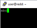
This means that all outlets are currently turned off. Suppose we want to turn on the second outlet. Press the capital 'B'. There is no reaction on the screen. Press '?' Again, we get a new line with the answer:

Everything works. Do not forget to turn off 220 volts (command 'b'). You can exit the terminal by successively pressing ctrl + A, then X. The experiment is complete.
SPI and I 2 C tires
SPI buses (which can also work in Quad-SPI mode) and I 2 C are implemented in combination with universal bridges. That is, in general, the complex has two bridges, each of which can be switched on either in SPI mode or in I 2 C. In the structural diagram, the corresponding section looks like this:

The essence of turning on the final buses is visible from the electrical circuit diagram. Consider only one of two controllers:
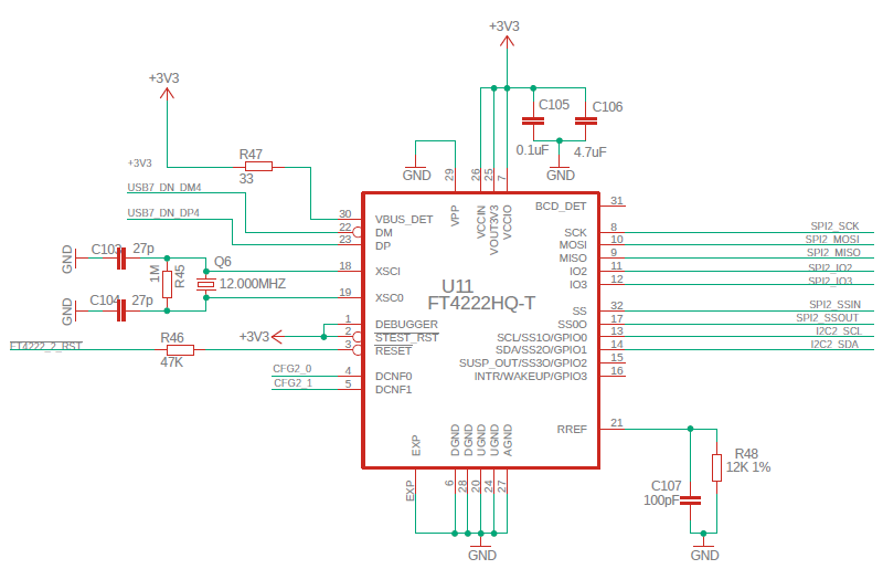
Thus, the SPI and I 2 C buses do not intersect in any way. Restrictions on their sharing are determined only by the restrictions laid down by FTDI in the FT4222H controller. Unfortunately, the documentation states that only one interface can be active at a time:

How to control the lines CFG1_0..CFG1_1 and CFG2_0..CFG2_1, we will meet in the next article. Now we believe that they are all nullified.
In general, the work with the controller is very well described in the document FT4222H USB2.0 TO QUADSPI / I2C BRIDGE IC , therefore we will not consider the features of the control modes of the controllers. Everything is very clear from the mentioned document.
As for software support, its description can be found in the no less remarkable document AN_329 User Guide For LibFT4222 . We have already worked with the FTDI bridge twice: in the second half of this article and in the second half of this . Therefore, comparing this document with these articles, you can quickly figure it out and start writing your own code. Let me just show you the reference code that sends data to the SPI bus, without dwelling on the details of its implementation, it all painfully looks like an already parsed work with FT2232.
Code that sends data to the SPI bus.
#include "../ftd2xx/ftd2xx.h" #include "../LibFT4222/inc/LibFT4222.h" void SpiTest (int pos) { FT_HANDLE ftHandle = NULL; FT_STATUS ftStatus; FT4222_STATUS ft4222Status; // ftStatus = FT_Open(pos, &ftHandle); if (FT_OK != ftStatus) { // open failed printf ("error: Cannot Open FTDI Device\n"); return; } ft4222Status = FT4222_SPIMaster_Init(ftHandle, SPI_IO_SINGLE, CLK_DIV_4, CLK_IDLE_LOW, CLK_LEADING, 0x01); if (FT4222_OK != ft4222Status) { printf ("error: Cannot switch to SPI Master Mode\n"); // spi master init failed return; } uint8 wrBuf [] = {0x9f,0xff,0xff,0xff,0xff,0xff,0xff}; uint8 rdBuf [sizeof (wrBuf)]; uint16 dwRead; ft4222Status = FT4222_SPIMaster_SingleReadWrite (ftHandle,rdBuf,wrBuf,sizeof (wrBuf),&dwRead,TRUE); if (FT4222_OK != ft4222Status) { printf ("error: Error on ReadWrite\n"); } else { printf ("received: "); for (int i=0;i<6;i++) { printf ("0x%X ",rdBuf[i]); } printf ("\n"); } FT4222_UnInitialize(ftHandle); FT_Close(ftHandle); }
SPI Bus Parts
Code developers for microcontrollers often use the SPI bus as a generator of a predetermined frequency. Indeed, pulses generated purely programmatically via GPIO lines depend on many factors. Firstly, branching, spinning the loop, requires CPU cycles. Secondly, interruptions, DMA and other unforeseen factors may interfere with the processor. SPI is more or less stable, know yourself manage to put bytes into the buffer. A typical application of the SPI block, which has no direct relation to this SPI itself, is the control of RGB LEDs, for which the accuracy of setting the duration of pulses is very important.
Unfortunately, this is not acceptable for FTDI bridges. The above code fragment will generate these pulses on the bus:
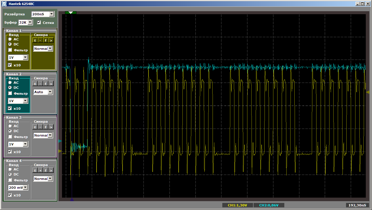
In this case, the SPI rules are not violated, from the point of view of this bus, everything works correctly. Just keep in mind that custom solutions customary on controllers will not work here. True, the complex has a lot of free USB connectors. All non-standard blocks can be developed separately and connected to them.
Tire parts I 2 C
The only thing that makes sense is to indicate the absence of pull-up resistors for the I 2 C bus on the complex side. But this is normal: on the side of the working device, there is still a lift. Nowadays, a pull-up can be to any voltage, so it is logical that it is set on the target device.
Conclusion
Today we gained practical skills in working with tires implemented by FTDI bridges. In general, working with them is standard, it’s just that all the knowledge has been consolidated into a single article, so as not to look for them bit by bit. Next time we will consider a module that controls non-standard devices, implemented on the basis of the STM32 controller. In the structural diagram, this section corresponds to it:
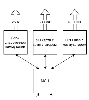
But really, everything is a little more interesting there ...