The article describes the method of multiplexing the use of port D of the ATMEL 328P microprocessor (Arduino NANO) in order to provide alternate byte output to the display and exchange via the serial channel.
I somehow assembled a device for monitoring the level of carbon monoxide (CO) from unnecessary elements - a display from Nokia N95, Arduino NANO with bad ports (D3 and D11, broken due to an unsuccessful short circuit to +400 volts when debugging a high voltage generator), boards playing sound bites and carbon monoxide sensor MQ7. All these details to one degree or another were faulty (except for the sensor) and could not be found in any other projects. Oddly enough, it turned out that the device is very useful when using a stove in the country. The summer of 2019 turned out to be non-hot and I heated the stove almost every day for a couple of weeks in July, combining pleasant (meditation on the flame) with useful (recycling sawn garbage trees). It turned out to be very easy to control the combustion modes, all manipulations with the flaps were immediately reflected in the readings of the device, which made it possible to control the stove intelligently. The device is not described in this article; there are plenty of such devices on the Internet for every taste. A distinctive feature of my device is the function of continuous monitoring of the health of the CO sensor based on a comparison of the stored reference curve and obtained in real time, as well as the high reaction rate to changes in the CO level achieved by comparing the data stored in the previous cycle with the current ones.
The focus of this article is on increasing the speed of the processor and the display with parallel byte data exchange.
The display has a parallel byte exchange and, despite the use of all the methods known to me for increasing the exchange rate, the output to it turned out to be rather slow. The main reason is the need to bit-wise output a data byte to different bits of different ports, since Arduino Nano does not have a single full-fledged port with a width of one byte. This output mode requires roughly 8 times more time than writing a byte to a register. NANO has a single full-fledged port D, but its least significant bits are used for a hardware serial port, through which sketches are downloaded to the processor and the sketch is exchanged with the host machine.
I have found a relatively simple way to use byte output to the display. This method consists in alternately using port D to output data to a display and in exchanging data over a serial channel.
The proposed method can significantly increase the speed of integral exchange with the display (about 3 times in my measurements). By the word “integral” we mean that the total times of performing the operations of rendering the screen at the macro level were measured. It is likely that measuring time at the level of atomic I / O would give a significantly greater gain (in the region of the same order).
The measurements were carried out on a specially assembled model (see Figure 1) in the following way:
- In the test program, timestamps were placed with the output to the host machine.
- The display was connected to pins D2 - D9, a test program was loaded, in which the byte was output by distributing the byte by bits.
- The display was connected to the terminals D0 - D7, a test program was loaded, in which the byte was output using the PORTD = data command.

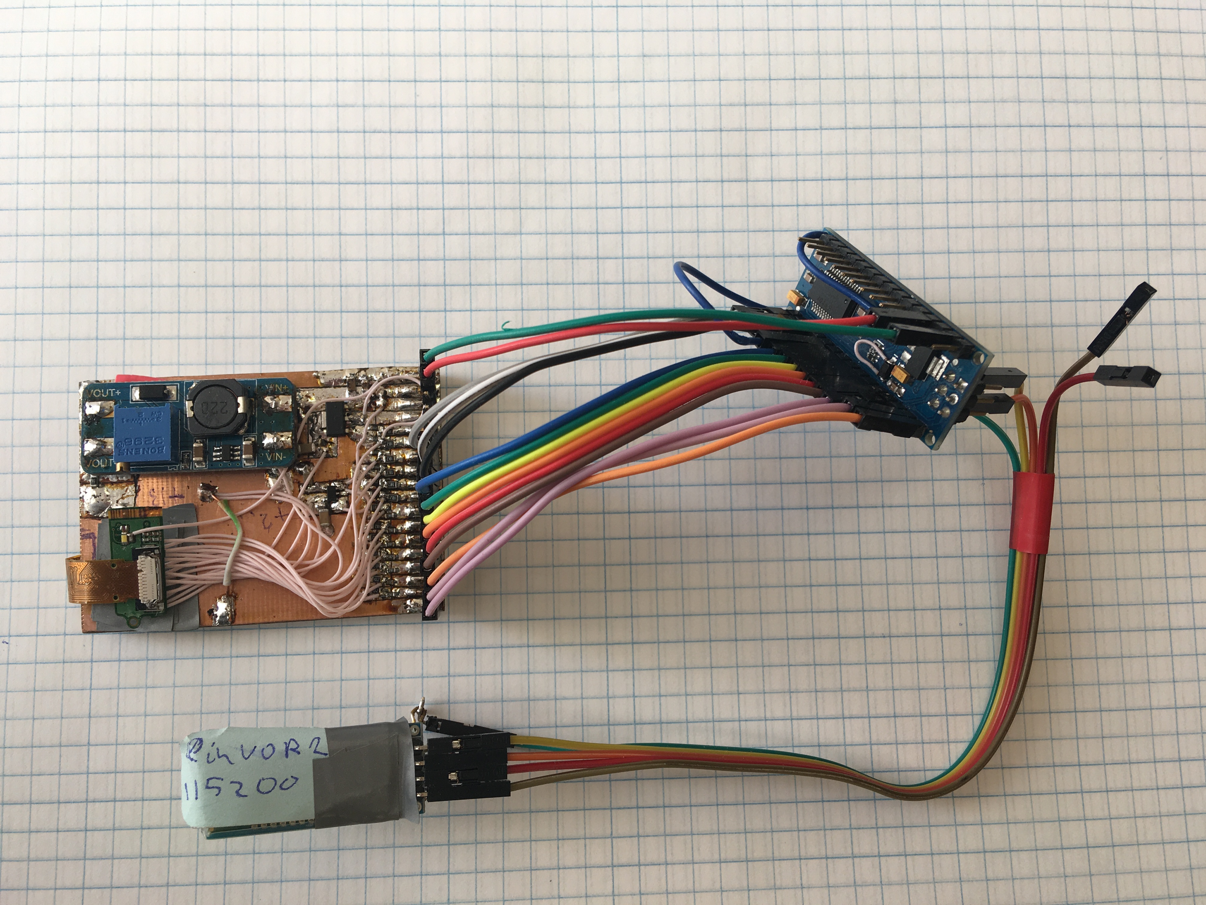
Figure 1. Photos of the layout for testing output multiplexing
The programs are exactly the same, switching the output method was carried out by changing the names of the SendDat and SendCom routines to SendDat1 and SendCom1, respectively.
The output of the program to the built-in serial monitor was recorded in OneNote and analyzed.

Figure 2. Measuring the time it takes to display in the byte-output mode
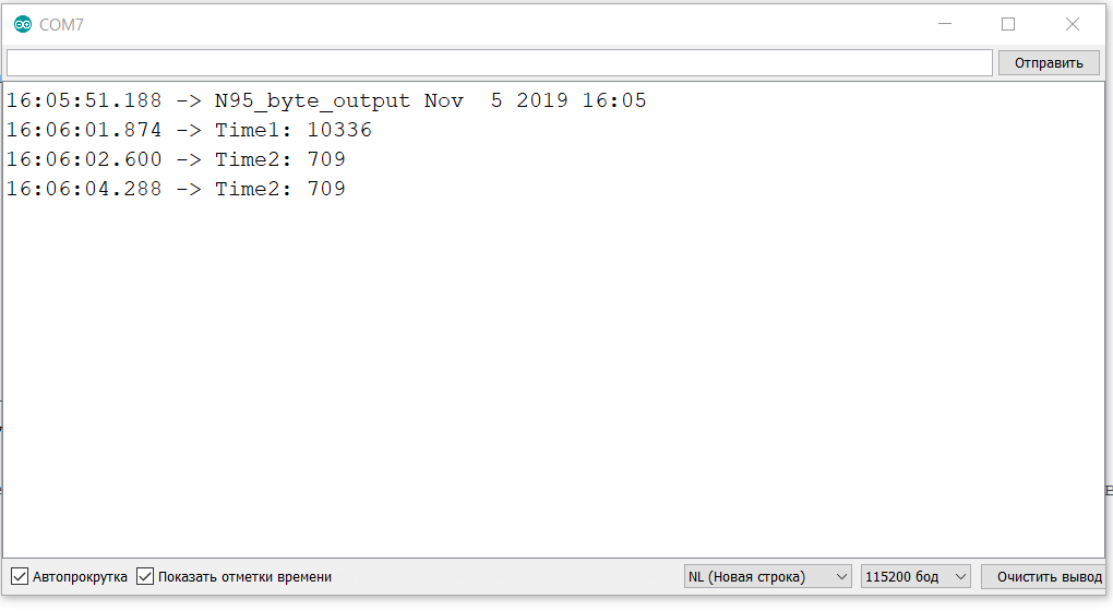
Figure 3. Measurement of screen time in bit output mode
The measurement results are summarized in table 1.
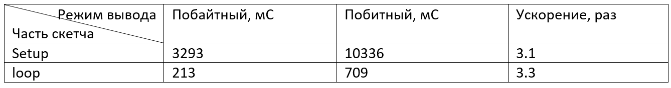
Table 1. Integrated gain in exchange rate
The disadvantages of the proposed method are the need to use additional commands to switch display modes and exchange via a serial port.
You can also expect some difficulties when receiving data from the host machine, reception is possible only with the explicit inclusion of the serial channel mode, which requires a clear time-based organization of processes in the sketch.
A study of the processor manual gave the following information: enabling the serial port mode intercepts the control of the D0 and D1 legs at the hardware level. This means that attempts to control the legs from the sketch will not give the desired result.
Further study of the issue showed that if you do not include the serial port in the sketch with the Serial.open () command, then the entire port D remains at the user's disposal. You can put the port into output mode on all legs with the DDRD = 0xFF command and output the entire byte with the PORTD = data command at the same time, where the data variable contains the output data.
Putting port D in output mode is enough once (in Setup). Subsequent on-off of serial communication mode does not affect port D mode - it remains in the 8-bit parallel output mode. When the serial exchange mode is turned on, the terminals D0 and D1 will go into the receive and transmit modes, respectively. “1” will appear on the D1 pin, regardless of the previous state of the D1 bit, and this “1” will be on this pin all the time while the serial transmission mode is on, except for the moments of the symbol transmission. When the serial transmission mode is turned off, the outputs D0 and D1 will go into the output state and the signals from the output register will appear on them. If in the output register in place of D1 there is “0”, then a negative differential will be generated at the output, which will lead to the transmission of the spurious character to the serial channel.
Now let's consider the question - will such use of port D prevent downloading programs? When the program loads, the processor is reset by the pulse that is generated by the FT232RL USB port controller (or its analogue CH340) when the DTR signal is set. The DTR signal goes from 1 to 0 and a negative drop through the capacitor resets the processor. After a reset, the processor turns on the serial port, starts the bootloader and receives the program code. So - changing the operation mode of port D does not interfere with the normal loading of the sketch.
If the sketch requires output to the serial port, then the Serial.open () command is enough before the output commands.
However, there is subtlety. It consists in the fact that the RxD input of the FT232RL chip remains connected to the TxD output and the data going to the display is received and sent further to the host machine. These data look like noise, although in fact they are not (Figure 4).

Figure 4. Screen view in byte output mode without blocking
There are two ways to deal with this unnecessary signal.
The first way is software. It consists in the fact that in the sketch before the output, the Serial.println () command is used to create a new line before the output of useful information. This will make it easier for the program in the host machine to analyze incoming lines and highlight useful information from the sketch.
The second way is hardware. The RxD input of the FT232RL is connected to the TxD output via a 1 kΩ resistor. To block the transfer of information, just connect the RxD FT232RL input to "1". To make this the easiest way is one of Arduino's free conclusions. I used the output of D8. To perform this action, I soldered to pin 7 of the RP1B resistor with a nominal value of 1 kOhm of wires with a connector at the end, passing it through the holes in the board for mechanical fixation. In Figure 5, this connection is shown by a red line, Figure 6 shows a photograph of the soldering point.
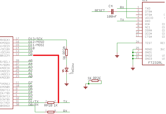
Figure 5. Part of the Arduino Nano circuit
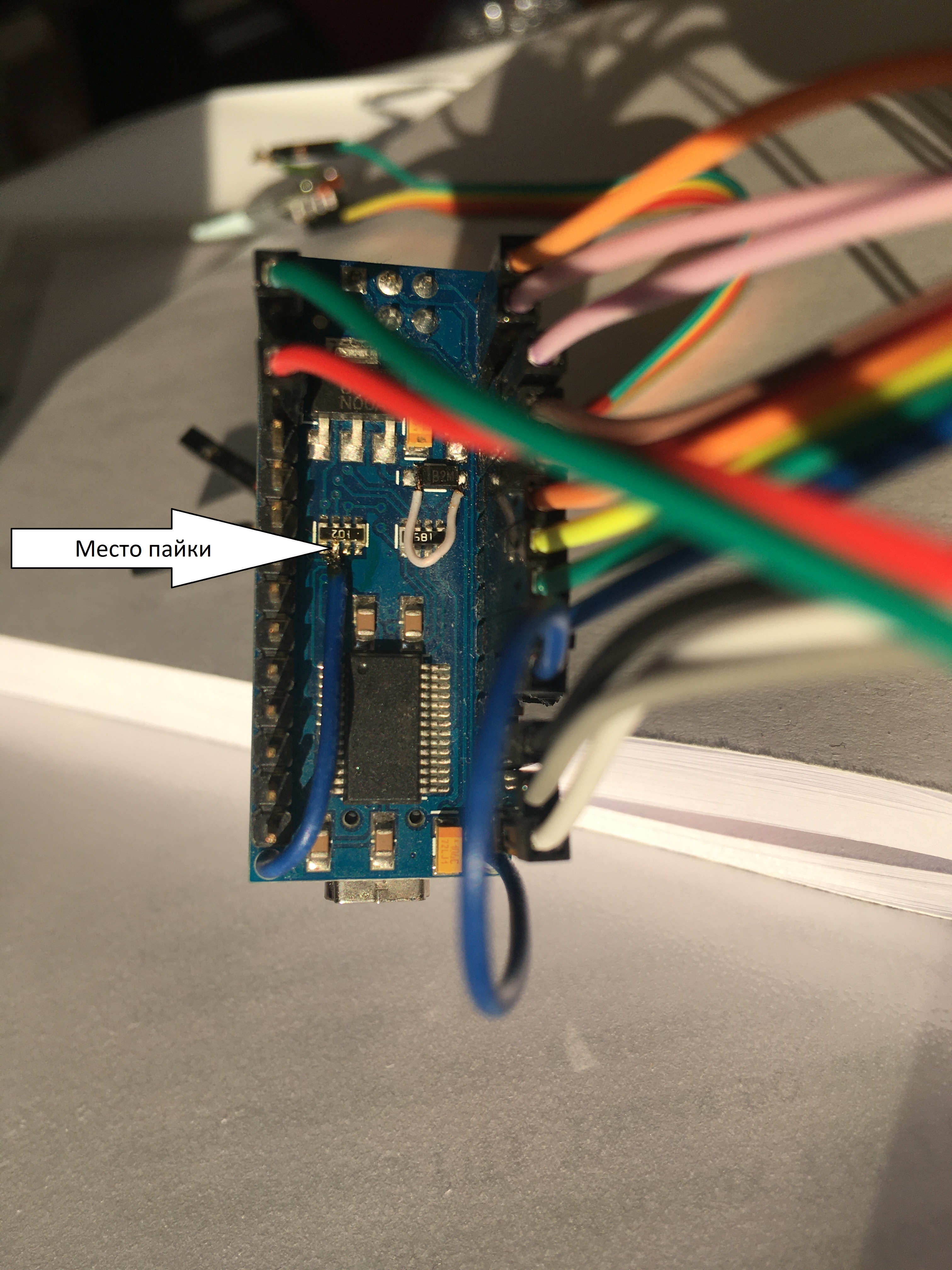
Figure 6. Soldering point for an additional wire in Arduino NANO
This mechanism works like this: after reset, the D8 leg is in high-impedance input mode and the Arduino board does not interfere with the normal operation of the program loading mechanism into the board.
When you need to start controlling the display in the sketch, the D8 pin is switched to the active pin mode, it is set to “1” (this blocks the transfer of data from the TxD Atmel328P pin to the RxD FT232RL pin) and after that the Serial.end () command is executed ;. The procedure is important, because after switching off the serial transmission mode, bit D1 appears on the TxD pin, which is stored in the output register of port D from the previous byte record in this port. If bit D1 was “0”, then when the serial transmission mode is turned off, the processor leg will switch from “1” to “0” and this will generate a parasitic character transmission on the serial channel.
In the process of debugging, it also turned out that we had to wait until the end of the transfer of the entire buffer to the host machine before blocking the serial channel, otherwise some of the transmitted data would be lost.
When a sketch needs to enable data transfer via the serial port, it is necessary to turn on the serial transfer mode and turn off the blocking of serial data transmission by setting the reading mode on pin D8.
To perform these tasks, two routines were added to the sketch:
void s_begin() { Serial.begin(115200); // TxD USART. TxD "1", RxD pinMode(8, INPUT); // RxD FT232RL "1", RxD FT232RL }
void s_end() { Serial.flush(); // pinMode(8, OUTPUT); // FT232RL "1" . D8_High; // Serial.end(); // . TxD RxD D0(RxD) D1(TxD) D }
A full test program can be taken here .