Introduction
This device is designed to determine the temperature at a distance. Since I did not find the ready-made instructions for assembling this device that I needed, and I didn’t really want to buy for 2+ thousand, it was decided to do everything on arduino (not expensive and not very difficult).
Assembly instruction
To build the project we need:
- DS18B20 temperature sensor 1 meter. (Sealed)
- Screen 0.96 128x64 OLED
- Breadboard
- Papa Papa Wire Set
- Microcontroller Arduino Uno
- Resistor
To implement the project, we need to install the arduino IDE and several libraries at once:
- OneWire Arduino Library
- OLED I2C_OLED_I2C with support for Russian and Ukrainian languages.
- Dallas temperature
Let's talk a little about the breadboard. This breadboard is used for quick assembly of circuits without soldering and radio elements and a wire for connection. Development boards come in various sizes, but in most cases they consist of these identical blocks:
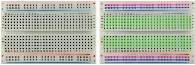
The electrical connection diagram of the sockets is shown in the right figure: five holes on each side, in each of the rows (in this case 30) are electrically connected to each other. On the left and on the right there are two power lines: here all the holes in the column are interconnected. The slot in the middle is designed for installation and convenient extraction of microcircuits in the cases. To assemble the circuit, radio components and jumpers are inserted into the holes.
After we figured out the breadboard, we can now move on to connecting the modules. First, connect the display as follows:
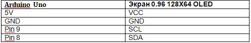

In this case, we connected 5V to “+” on the breadboard (yellow wire), and GND to “-” (white wire), so that later all the power on the modules should be connected to “+” and “-” on the breadboard.
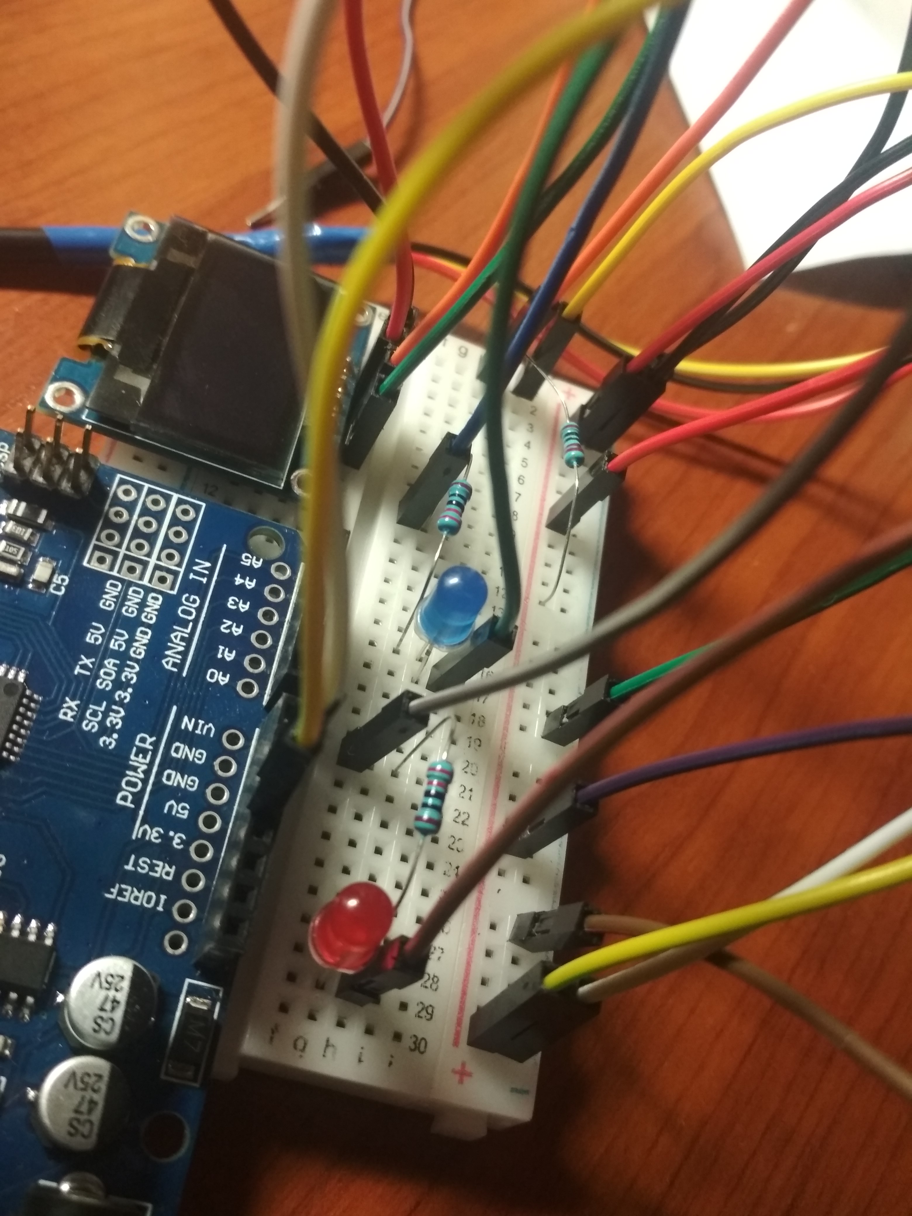
Next, connect the DS18B20 temperature sensor using a resistor as shown in the photo below:


In our case, for convenience, we connected all the sensor wires to the breadboard and connected the orange cable “Daddy” to Pin 10.
Half of the work is done, it remains only to connect signaling devices, namely: x2 LED (red for high temperature, blue for low) and a conventional piezo emitter (in common people “tweeter”). The LED is connected very simply, “+” is a long rod, and minus is a short rod. We insert it into the board, be sure to connect a resistor to it and use the “Dad-dad” wires to connect the short rod of the blue LED to 5 pin, and the short rod of the red LED to 12 pin.
Squeaker just connect the black wire to “-”, the red wire to 13pin.
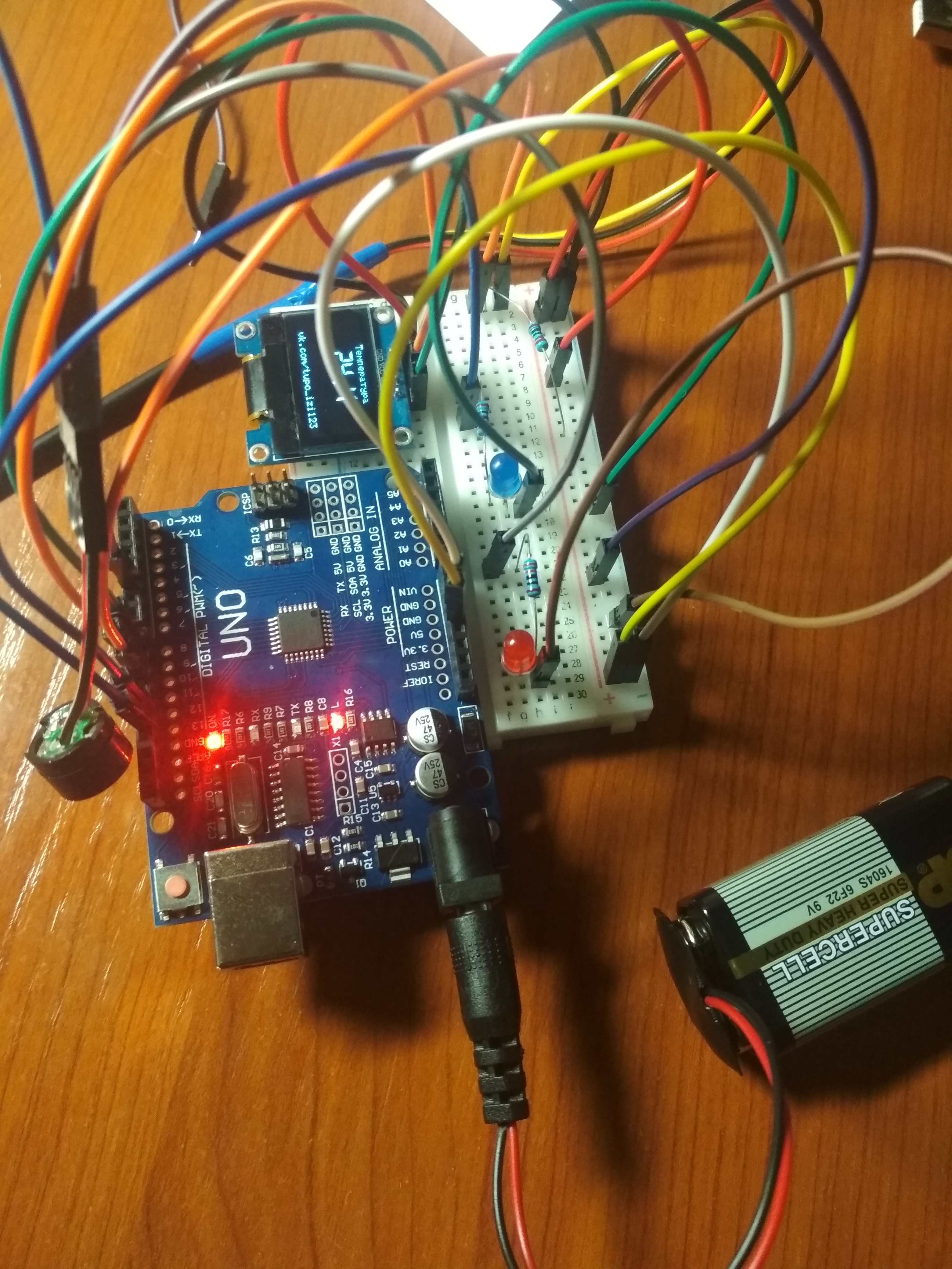
This is how it should work out:
The most important thing (sketch)
#include <Wire.h> #include <Wire.h> #include <OneWire.h> #include <DallasTemperature.h> // DS18B20 #define ONE_WIRE_BUS 10 // pin DS18B20 OneWire oneWire(ONE_WIRE_BUS); DallasTemperature sensors(&oneWire); #include <OLED_I2C.h> OLED myOLED(8, 9, 8); // , 8 pin-SDA, 9pin-SCL extern uint8_t RusFont[]; // extern uint8_t BigNumbers[]; // extern uint8_t SmallFont[]; // void setup() { pinMode(13, OUTPUT); // pin 13 pinMode(12, OUTPUT);// pin 12 pinMode(5, OUTPUT); // pin 5 sensors.begin();// myOLED.begin();// myOLED.setFont(RusFont); } void loop() { if (sensors.getTempCByIndex(0)>70){ // ( >70 ) digitalWrite(5,255);// tone(13, 2500); // 2500 delay(400);// 0.4 digitalWrite(5,LOW);// } else{ digitalWrite(5,LOW); } if (sensors.getTempCByIndex(0)<25){ // ( <45 ) digitalWrite(12,255); // tone(13, 2500); // 2500 delay(400); // 0.4 digitalWrite(12,LOW); // } else{ digitalWrite(12,LOW); } if ((sensors.getTempCByIndex(0)<70) and (sensors.getTempCByIndex(0)>45)){ noTone(13); // } sensors.requestTemperatures(); myOLED.clrScr(); // myOLED.setFont(RusFont); myOLED.print("Ntvgthfnehf", CENTER, 0); // myOLED.setFont(SmallFont); myOLED.print("vk.com/tupo_izi123", CENTER, 55); // myOLED.setFont(BigNumbers); myOLED.print(String(sensors.getTempCByIndex(0) , 1), CENTER, 10); // , myOLED.update(); delay(100); }
In this sketch, I set the temperature above 70 and below 45 degrees, but you can set any other (from -55 to +125 ° C).
Photos of the final product: