Communicating with software tracers working in CAD software for Cadence OrCAD / Allegro printed circuit boards, I sometimes noticed that people do not attach much importance to the color indication of fields in the Constraint Manager rule editor. Namely: users do not pay attention to the fact that some columns are painted in yellow.
In fact, the yellow color in the Cadence rule editor means that this check cannot be performed for any reason. The reasons may be different:
- Validation disabled by user.
- The conductive path is either not laid at all or not completed.
- Other reasons.
In most cases, there are no fatal situations in which errors appear that lead to inoperability of the software. Since OrCAD PCB Editor has a multi-stage mechanism for checking the project on DRC, just like that, you can’t turn them off in one go. However, sometimes because of an unfortunate knowledge gap, or because of inattention, situations are created that lead to incorrect situations in the project. For example, one developer told me how he accidentally turned off checking for shorting opposite lines with each other. Moreover, CAD software will not report an error in this situation, since verification is disabled by the user.
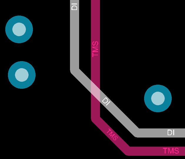
Intersection of one conductor by another without error message
The figure shows that the conductors of opposite lines intersect with each other. However, an error message does not occur. The reason for this behavior of the program is not clear to the developer, since during online tracing all the gaps set in the constant manager are saved and maintained.
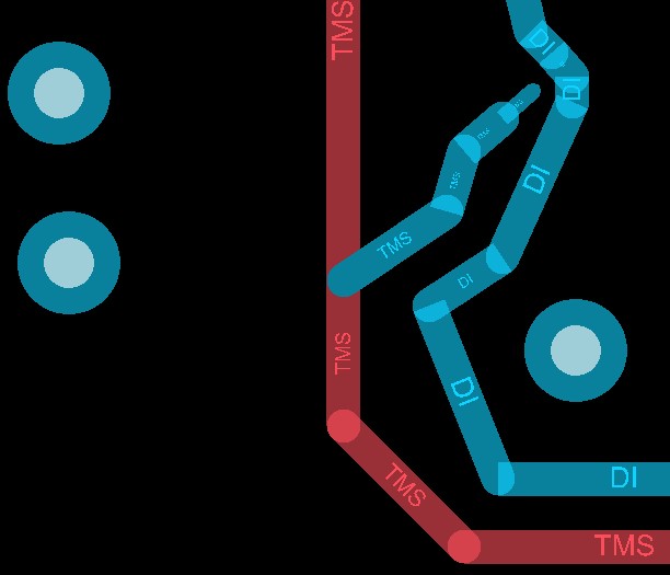
Gaps and rules in regions are supported when tracing
The absence of a DRC token lies precisely in the settings of Constraint Manager.
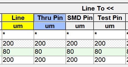
This is what disabled verification looks like in Constraint Manager
A yellow color in the Line-to-Line gap check section means that the check is not performed (or cannot be performed). Because of this, the DRC marker does not occur. Of course, partial disabling of checks is sometimes very convenient and can reduce the total time for checking a project, but .... This can lead to fatal consequences if, when submitting a project and generating files for production, the developer does not include all the necessary checks and does not conduct a final DRC check with them.
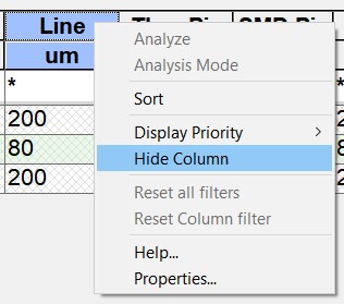
Disabling or enabling a particular test in Cadence is very simple: just click on the header of the cell of interest and select Analysis Mode from the drop-down menu.
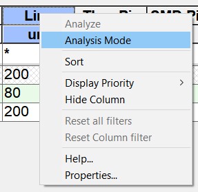
Quickly enable or disable certain types of checks
When the check is turned on, the color of the cap is gray; when the check is disabled, the color of the cap is yellow.
Why, when checking is disabled in Constraint Manager, the necessary gaps are still supported during tracing, and OrCAD PCB Designer prevents the user from accidentally making an error? This is precisely because the DRC verification system consists of two parts: Online DRC real-time checks, and Batch Mode DRC on-demand checks. Batch Mode DRC just shuts down forcibly in Constraint Manager. Online DRC continues to work if in the trace mode the value of the Bubble parameter in the Options window is different from the OFF state.
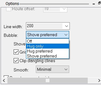
Possible values that the Bubble parameter can take
If the engineer does not want to see disabled checks or some sections in the Constraint Manager rule editor, then they can be easily hidden.
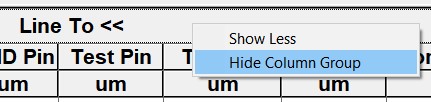
Hide a column or section from consideration
When the check becomes necessary again, it can be returned in the field of displayed columns.
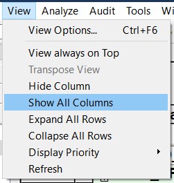
Return hidden columns
It is worth noting that the table editor of CAD rules Cadence Allegro / OrCAD, with all its power, is very convenient and easy to configure, and the checks themselves are performed quite quickly, so often there is no need to force something to turn off.
On the other hand, if it was necessary to disable some particularly slow checks, the developer can first save the “technological” file containing the settings for all the necessary checks, then disable them temporarily, and when issuing design documentation after tracing is completed, reload that technological file with all checks and run the final DRC.
Yes, by the way, if you recall the developer who turned off the short circuit test between the circuits - fortunately, the PCB manufacturer when he started the order drew his attention to the problem of circuit between the circuits, so that they managed to avoid financial and time losses. But, from experience in a company that was engaged in the manufacture of printed circuit boards, I can say that the problem of disabling "unnecessary" checks was very common for most customers, and did not depend on which CAD developers work. So do not forget to include them at the right time!