Brief Summary
Effective collaboration is a key factor in increasing productivity and creating high-quality products. Modern computer-aided design (CAD) systems and intelligent tools help engineers synchronize data and work together on the most important interdisciplinary issues of the project, while concentrating on their main task: to create innovation. Thanks to this approach, it is possible to best implement the designer's plan, reduce design time and bring the product to the market at the right time.

Supporting interdisciplinary collaboration accelerates innovation
Introduction
Modern customers, regardless of industry, are very demanding: their products must be more intelligent and have extensive functionality. In this regard, the use of electronics in traditional mechanical devices is growing at an unprecedented rate, and all these electronic components must be physically connected to each other and linked to the general layout of the product.
Sensors are installed in almost any equipment in order to combine devices into a single “smart” world. The signals from these sensors are transmitted by wire to the built-in units, drives and antennas. Separate wires are bundled together. As a result, a real “electrical nervous system” of a modern product is formed.
As a result of the fact that electronics and software begin to manage the mechanical components of the structure, the complexity of electromechanical systems is growing, the best of the existing design processes are quickly becoming obsolete and becoming ineffective, and it is becoming increasingly difficult for designers to keep up with the rapidly changing market requirements. Today it is no longer possible to simply transfer the finished project to the manufacture of a prototype in order to check whether the product works as intended. Engineers have to go beyond their area of specialization. For example, mechanical engineers often deal with electrical equipment, and electrical engineers with mechanical equipment.
The problem is the fragmentation of engineering disciplines
In the absence of a coordinated design process, the integration of product systems is carried out at the stage of manufacturing prototypes, that is, at the end of the development cycle. At the same time, the mistakes made at such late stages turn out to be very expensive. If they cannot be identified before the manufacture and testing of prototypes, the company bears significant costs - financial and time. In addition, such errors can greatly delay the release of a new product to the market.
Thus, the traditional separation of processes becomes ineffective against the background of the increasing complexity of the designed products.
Why?
- When electrical engineers and mechanical engineers work in various design systems, matching even the simplest questions becomes a big problem. “Are we talking about this wire or about that?”: For an electrical engineer, a wire is a line on an electrical circuit; for a mechanical engineer, the same wire is laid on a 3D model of a mechanical assembly. Due to the difference in approaches, misunderstanding, mistakes and design delays arise.
- In the absence of coordination of work processes, electrical engineers develop a set of wiring diagrams, specifications and drawings. Then, mechanical engineers should study the documentation and find out which wires require tracing on mechanical nodes. These works are carried out manually, which means that the risk of errors appears.

Fig. 1. The traditional separation of the design processes of the electrical and mechanical parts of products does not allow synchronization of individual parts of the project.
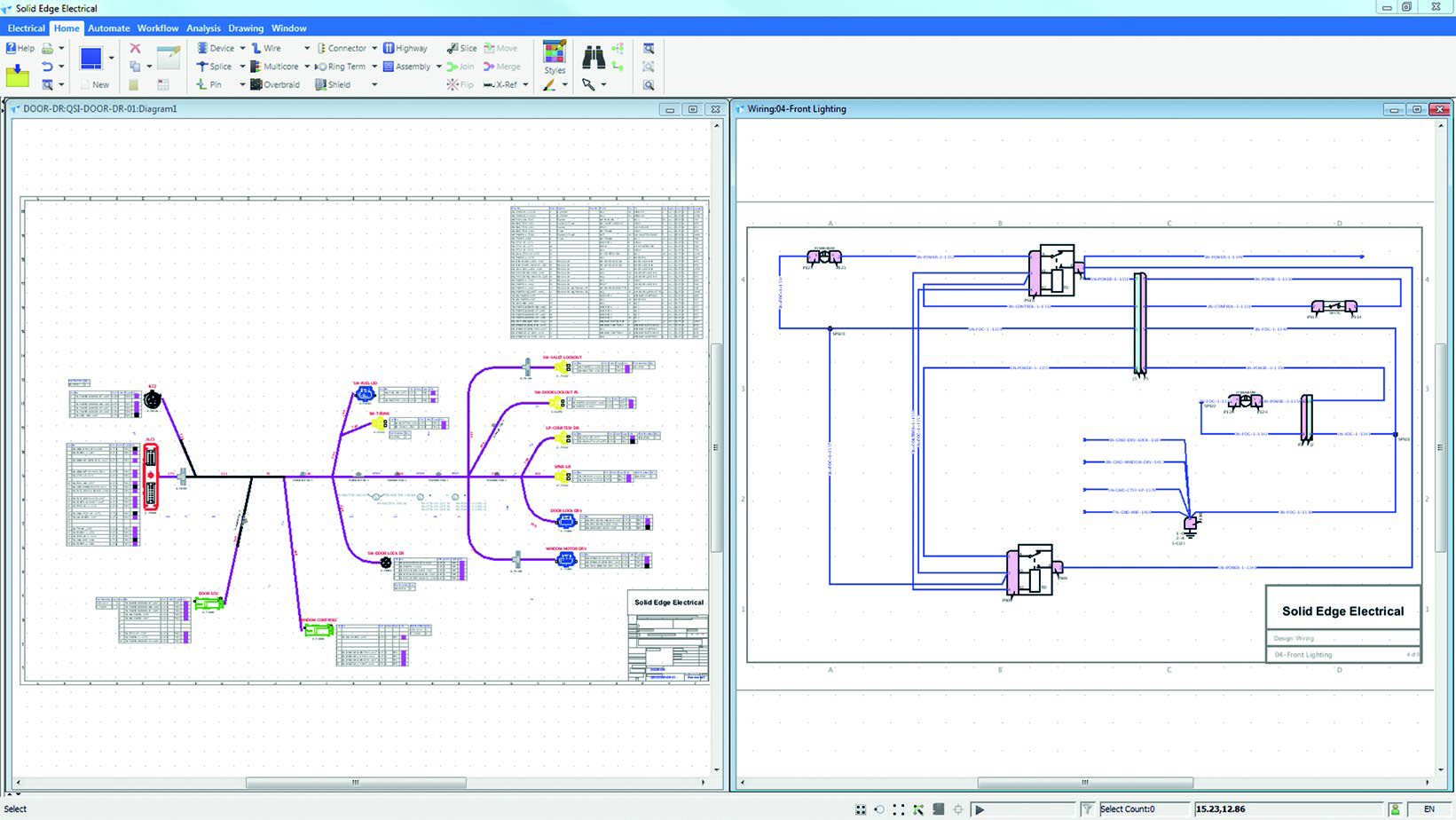
Fig. 2. It is a mistake to think that tracing and making wiring harnesses is a simple task.
- The design of the electrical part is rarely possible to complete the first time. Most often, this is a cyclic process with the participation of electrical engineers and mechanical engineers, while on each cycle the specialist has to re-examine the changes made.
As a result, design errors are passed on to the next stages, because of which it is necessary to carry out many cycles of manufacturing and testing prototypes.
In modern conditions, the scattered departments of the enterprise cannot work effectively. The electrical and mechanical parts of the project must be combined.
Obstacles to the integration of ECAD and MCAD systems
Unfortunately, ensuring the collaboration of users of electrical (ECAD) and mechanical (MCAD) CAD systems is not an easy task. The main problem is the traditional division of the project into electrical and mechanical parts. As a rule, electrical engineers and mechanical engineers “speak” different languages and use different tools. In addition, most often their jobs are spaced geographically.
The next difficulty is that the structure of the same object for the design of electrical and mechanical parts is represented differently in CAD systems.
In any MCAD system, an electronic unit is a specification in the form of fasteners, a housing, a printed circuit board and connectors. Moreover, in the ECAD system, the same module is a functional or electrical circuit, that is, a representation of a higher level than just the physical structure of the object. To perform a number of electrical functions, several printed circuit boards and connectors are used at once, which does not allow to unambiguously associate a specific function with a specific physical element of the product.
To provide the necessary functionality of the electrical part, considerable labor is required. During the design process, engineers select the appropriate connectors, terminals, screens, wire materials, etc. Also, when developing electrical systems, it is necessary to solve many problems of designing mechanical components. It is necessary to carefully trace the wiring of the product, taking into account the issues of electromagnetic compatibility. The tracing process should exclude the physical intersection of the electrical wiring with the parts, correctly calculate the length of the wires (based on real bending radii) and take into account other factors - for example, the correct choice of wiring attachment points.
As a result, to create a really good electrical system, electrical engineers and mechanical engineers perform many design cycles. They need to exchange design data and work closely.
Previous attempts to support such collaboration did not bring significant success. To integrate ECAD-MCAD-systems, anything was used: stickers, e-mail, Excel files. For obvious reasons, such approaches were doomed to failure.
It is possible, in principle, to design an electrical system using a combination of a universal editor for constructing circuits, spreadsheets and a 2D CAD system, but there are many risks:
- The elements developed in each of these systems are in no way interconnected. If changes are made to the electrical circuit and forgotten about them, the drawings and specifications will not reflect the new design decision.
- All elements of the scheme, the specifications of the drawing are nothing more than lines and symbols. It is absolutely impossible to perform numerical modeling and testing the functionality of systems with their help. If the fuse rated current is too low, the engineers will not know that it will blow, until the prototype is tested.
- In the absence of automation in the transition from electrical engineering to routing electrical wiring through mechanical components, mechanical engineers are forced to manually deal with the documentation for the electrical system to find out where and which wiring harnesses need to be laid.
Fortunately, new computer-aided design processes have emerged that successfully cope with these challenges.
Intelligent processes of ECAD-MCAD-design support the collaboration of specialists creating the electrical and mechanical parts of the project.
Numerical modeling predicts the characteristics of the electrical system, which allows you to check and optimize the design solution, and cross-checking the design in various applications enhances integration.
A new approach to the joint development of electrical and mechanical parts of the product
Designing modern electromechanical systems is not an easy task, which is a cyclic process with a wide range of limitations. Enterprises need new, automated and intelligent solutions that ensure the collaboration of specialists. However, until now, many decide not to develop an integrated design process, justifying that it requires significant costs. In this regard, it is necessary to ask another question: what losses will occur if the product does not enter the market at an opportune moment?
The quality of the electrical part has a tremendous impact on the success or failure of a new product, and numerical modeling and calculations serve as the basis for effective control of design decisions in the early stages. Numerical simulation of electrical systems at the very beginning of development is able to identify problems requiring a complete alteration of the entire basic architecture of the electrical part.
The electrical system is closely connected with the mechanical components, so changes in the electrical part often require adjustments to the mechanical part as well.
Such changes in both electrics and mechanics are much simpler and cheaper to carry out at the earliest stages of product creation.
The introduction of new intelligent design systems provides developers with full access to all product information. Based on this information, numerical modeling is performed - the basis of the design processes of integrated electromechanical systems, with the help of which the need for prototypes is reduced, time and money are saved.
Computer methods of modeling and control of design decisions of the electrical part are a significant step forward in terms of checking the integrity of the structure. The possibilities of this approach are much wider than when using traditional prototypes.
Typical Intelligent Design Process
An electrical engineer develops a specification for the elements of an electrical system, which he then integrates into an efficient 3D design environment — for example, Solid Edge from Siemens Digital Industries Software. Such integration allows for the design of the electrical part to take into account the restrictions imposed by the mechanical structure, indicates the presence of places with high humidity, temperature and other dangerous factors. On the other hand, when designing the mechanical part, the designer will leave enough space for wiring, as well as provide the required bending radii of the bundles. Due to the interdisciplinary context, electrical and mechanical engineers quickly identify inconsistencies between the electrical and mechanical parts of the project.
The mechanical engineer must ensure that the harness with all the required wires can be laid in the available space. However, modeling these wires in an MCAD system is too complicated and time-consuming task. Instead, a description of the electrical system is created in a special module such as Solid Edge Wiring and Harness Design. The maximum allowable diameter of the wiring harness, determined on the basis of restrictions imposed by the mechanical part, is transferred to the Solid Edge module, which checks that the designed harness does not really exceed this diameter. To do this, the Solid Edge Wiring and Harness Design module provides automatic verification of design rules.
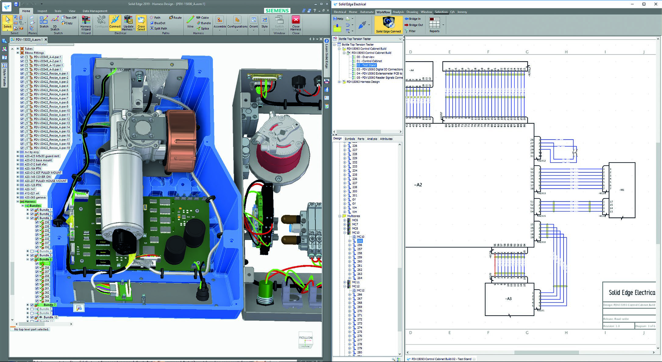
Fig. 3. Cross-validation features in Solid Edge Wiring and Harness Design
If the harness is equipped with clamps, insulating sleeves and shrink tubes, interdisciplinary interaction of specialists is also required to take into account their influence. Such objects are best created in a 3D MCAD system, and then add data on the electrical part obtained from the ECAD system to them. This associative connection allows you to automatically design wiring harnesses and accurately determine their parameters.
At the end of the joint development, each engineer receives a clear idea of how the part of the project he developed will function as part of the entire product.
Intelligent approach to the design of electromechanical components
Solid Edge modules for electrical system design are targeted at medium-sized enterprises, for which parameters such as ease of implementation and low total cost of ownership are especially important. The wide capabilities of this system go far beyond the traditional functions of creating electromechanical components. In particular, the modules perform numerical simulation of currents and voltages, identify errors such as short circuits, and calculate fuse ratings.
These features, as well as the capabilities of computer-aided design of wiring harnesses and preparation of documentation in the Solid Edge Wiring and Harness Design module help our customers win the competition even in the absence of much experience working with similar tools.
When used in conjunction with the Solid Edge 3D CAD system, the Solid Edge Wiring and Harness Design module enables the efficient collaboration of electrical engineers and mechanical engineers.
- Full information about the electrical part of the project is transferred to Solid Edge 3D, so the mechanical engineer receives a complete list of the placed electrical components and connections requiring tracing. Moreover, Solid Edge knows which elements should be connected and how, so that the system performs 3D-tracing of wires, cables and bundles automatically, reducing the likelihood of errors due to human factors.
- Reliable transfer of changes between the electrical and mechanical parts of the project. Cross-checking and visualization provide control of the signal flow directly on the 3D model, which helps in choosing the optimal path that excludes the occurrence of electromagnetic interference. When one of the engineers makes changes to his part of the design, they are immediately visible to all other participants in the development. This minimizes the number of design errors.
- Interactive selection of objects. When an electrical engineer selects a wire on a wiring diagram, the same wire is highlighted on a 3D model of a mechanical assembly. And vice versa: when choosing a wire on a 3D model, it is highlighted on a wiring diagram. This greatly facilitates the identification and elimination of interdisciplinary discrepancies.
- Intelligent graphics, specifications, and drawings are different representations of the same elements, connectors, or wires. Any change in one of them entails the automatic display of this change in other materials.
- Electrical engineers now perform numerical simulations and calculations, checking the proper functioning of the developed system. Numerical modeling can reveal
the state of the electrical system, which will lead to a blown fuse, and long before the prototype tests. - Design information is transmitted in the form of a list of tasks for a mechanical engineer tracing the wiring of the product.
The Solid Edge Wiring and Harness Design module successfully solves the design problems of electromechanical devices. The integrated multidisciplinary solution is based on the technologies of the leading developer of electrical engineering systems Mentor Graphics, a member of Siemens Digital Industries Software. All solutions for the design of the electrical part, including the Solid Edge Wiring and Harness Design module, were created by the same developer and deeply integrated, which would be impossible if combined with third-party applications or independently developed additional modules. When used with the Solid Edge 3D CAD system, the Solid Edge Wiring and Harness Design module helps design electromechanical systems faster and cheaper.
Conclusion
Electrical systems play a critical role in most modern products. They provide the necessary power to the electronics, as well as the precise and effective interaction of many systems. Without reliable electrical systems, modern products would simply become inoperative.
The electrical system is closely connected with mechanical components. For example, the impedance of a conductor depends on its length and the resistivity of the material. In the first systems for designing and calculating the electrical part, the lengths of the wires were specified manually. As electrical equipment became more complex, manual processes became a thing of the past, and there was a close integration of the development stages of electrical and mechanical parts with unified interdisciplinary models. Now the two-sided ECAD-MCAD interface is used for this. The ECAD system reports all the necessary attributes, including points connected by each conductor. The MCAD system then traces the wire, cable, or bundle in 3D and sends the actual lengths back to the ECAD system. Such an interdisciplinary process reduces design time.
It has long been known that collaboration improves productivity and helps create highly efficient designs. State-of-the-art CAD systems and intelligent tools help engineers synchronize data and work together on critical interdisciplinary project issues. Thanks to this, it is possible to best implement the designer's intention and achieve success the first time.
A highly integrated electromechanical design system, such as Solid Edge Wiring and Harness Design, provides interdisciplinary collaboration, eliminating the need for engineers to constantly hold meetings, discussing errors that occurred when manually entering changes. An intelligent design technique allows you to evaluate the effects of changes on the electrical and mechanical parts in a single environment. Thanks to this, engineers have more time left for their main task: to create innovations.
About Siemens Digital Industries Software
Siemens Digital Industries Software is the business division of Digital Industries at Siemens, a leading global provider of digital transformation software solutions. Siemens Digital Industries Software creates new opportunities for the development and implementation of innovations in the business processes of industrial companies. The organization collaborates with companies of any size, helping to translate ideas into reality, transform the processes of creating and operating new products.
The headquarters is located in Plano, Texas (USA). The number of customers worldwide exceeds 140 thousand.
For more information on Siemens Digital Industries Software products and services, visit.