Prologue
For a year, it seems in 2009, a water analyzer was purchased for one project. Due to the fact that it was supposed to be used to ensure the operation of technological equipment, the device was purchased complete with an autosampler.
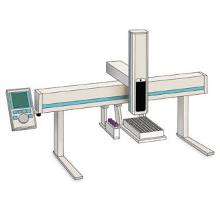
This is essentially a CNC manipulator with four degrees of freedom of movement for automatically feeding samples to the analyzer.
He worked for about 10 years and filed more than thirty thousand samples with some minor troubles, which, however, were overcome with "little blood."
At the beginning of this year he was tired - the Z axis failed, vertical movement.
That is, the manipulator simply stopped “seeing” it. Due to a number of circumstances of official maintenance, the measuring complex never had any minor problems (PSU repair, flashing after a FLASH failure) were resolved independently. Then I had to look for officials, from whom it turned out ... Some features:
- it turned out that the manipulator is not just old, but disastrously old
- he was old and discontinued upon purchase
- no documentation for it
- all electronics must be changed
- parts are available but cost more than new
- one hundred percent guarantee that with the replacement it will work no
Some features that were known to me:
- the manufacturer’s firmware does not work with the analyzer (it’s good that a backup was made),
- the bootloader is also apparently changed, as the factory firmware “as is” is not accepted
- There is no way to “reflash” the bootloader, so buying electronics for $ 6k is useless
- the mechanics are in excellent condition, as I periodically serviced it
- Zero (Hall) sensors are alive
Thus, two options turned out:
- purchase of a new analyzer from the manufacturer for $ 17k and an incomprehensible delivery time
- remaking all electronics and writing programs
Part One, hardware
To begin with, I decided to make sure that the mechanics are working at a voltage of 12v (against 37 in the original). Decided to lower due to the fact that the power half-bridge control of the drive motors decently warmed up. Therefore, the drivers A4988, CNC nameplate and Arduino NANO were pulled out of the nightstand. all this was docked, flashed by the famous grbl project and interrogated with bias. The maximum stepping frequency was obtained for each drive, step division coefficients, driver currents were adjusted.
It turned out that XY does not heat up at all, and they give out quite a suitable speed. The current for drive Z - had to be screwed to the maximum, due to dividing by 8 and decent consumption at the beginning of the upward movement, since it pulls a heavy mass of two SD and entrails, while the driver chip warmed up to 50 degrees even with a radiator. In the final design, I had to add a cooler on blowing opposite to this drive.
In the end, instead
it turned out
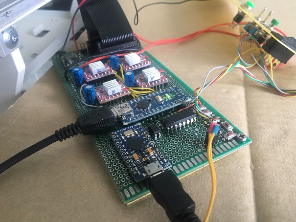
The Arduino Pro Micro will be a separate song. In the background is a panel with toggle switches for selecting an operating mode, start and reset buttons.
Now about tripe. As I said, all Hall sensors survived. Of these, XYs are only interesting in different triggering logic. If at Y the sensor opens OK when approaching the magnet, then at X the magnet is constantly opposite the sensor, and in Zero-X and further between them there is a magnetically soft shutter that shields the sensor from the magnet, while it closes OK. In light of this heterogeneity, there is a need to understand where to go when searching for zeros. To do this, the original design provides a parking position at the end of work. However, it was implemented in no way: when turning off the power, I had to catch my head on the Z axis and manually forward it to the parking position.
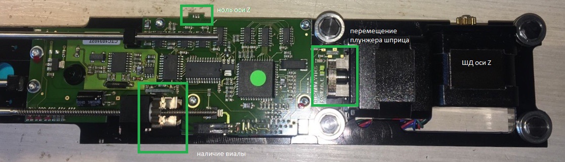
About Z is the main story. There, in the case Z, the syringe plunger drive still lives, without a zero sensor, but with a double rotation sensor - almost an encoder. And there is also a sensor for pressing the vial with a breakdown, implemented by screw transmission and also a Hall sensor. Both of these rotation sensors are brass gears passing with teeth past the Hall sensors with magnetization.
Why did I need a magnetic encoder (as part of my private task) I did not understand, and therefore replaced it with a zero sensor for the plunger drive, since the Halls were there, in the nightstand, as well as a tiny neodymium magnet from the DVD lens drive.
Instead of this
It became
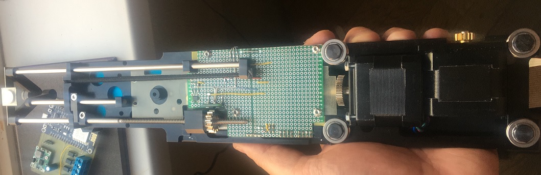
The main problem of sculpting iron was to cram, well, you yourself understand. I really didn’t want to keep something in a separate box, as a result, everything fit in the places intended for this, but now I would do it a little differently.
Part two, software
Tests on the CNC nameplate showed decent speed. BUT! If you try to offer the SD immediately the STEP frequency corresponding to this speed, then you won’t get anything except a growl in place. In order to reach decent speeds of movement, the stepper motor must be accelerated, just as if you cherish the gears and drive rails (well, or ballscrews, or belts) then slow it down smoothly. Because the trivial code has grown a bit.
Since it’s almost indecent to come to the “Robotics” section with an article without a code, for example, drive Z (for blame). When issuing a frequency to STEP, digitalWrite does not have time, you have to pull the port directly. It was probably delayed, and delay, but the code came from XY control, and simultaneity is needed there.
//***************** Z ************************* void movement_z (unsigned int tz, int spd) { long interval_z; long spd_z = 2000; unsigned long cur_micros; unsigned long prev_micros_z =0; int half_z; byte full_mask = mask_z; int dz = tz - z; z=z+dz; if (dz <0) digitalWrite(pin_dir_z, HIGH); else digitalWrite(pin_dir_z, LOW); dz = abs(dz); half_z = int(dz/2); interval_z = spd; do { if (dz>0){ cur_micros = micros(); if(cur_micros - prev_micros_z > spd_z) { if ( dz>half_z ) {if (spd_z > interval_z) {spd_z = spd_z - 5;} else spd_z = interval_z;} if ( dz<300 ) {if (spd_z < 1000) spd_z = spd_z + 2; else spd_z = 3000;} prev_micros_z = cur_micros; if (dz>0) {PORTB = PORTB | mask_z; dz--;} }} delayMicroseconds(5); PORTB = PORTB & B11110000; } while( dz != 0); } //*************************************************************
In the set of level functions:
- low - go back and forth, find something-don't-know-what
- medium - calibrate to zeros, draw a syringe, make a sample of the sample
- high - a sequence diagram of the bypass of the nth number of vials on a pallet
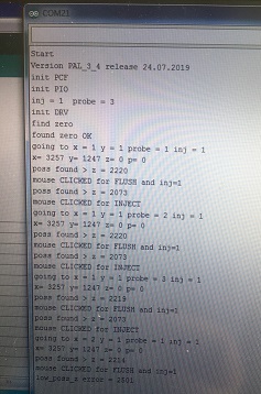
The program starts by initializing the ports, reading the specified configuration from the switches on the rear panel and, after pressing START, working out the sequence diagram until you find a position on the pallet in which there is no vial with the sample.
The main sequence diagram looks like this:
inline void frame_1(){ for (unsigned int i=0; i<6; i++){ // 6 for (unsigned int j=0; j<9; j++){ // 9 for (unsigned int k=1; k < probe+1; k++){ for (unsigned int l=1; l < inj+1; l++){ sound1(); delay(1000); if (inj == 2) {tone(tone_p,5000);delay(200);noTone(tone_p);delay(200);tone(tone_p,5000);delay(200);noTone(tone_p);} if (inj == 1) {tone(tone_p,5000);delay(200);noTone(tone_p);} Serial.print("going to x = ");Serial.print(j+1);Serial.print(" y = ");Serial.print(i+1); Serial.print(" probe = ");Serial.print(k); Serial.print(" inj = ");Serial.println(l); show_xyzp(); movement_z (0,450); movement_xy (prime_x-j*272, prime_y+i*372,500); movement_z(1800,300); if (z>2500) ost(); fill(); while(sensor()); if (inj == 1) {click_mouse(); Serial.println("mouse CLICKED for FLUSH and inj=1");} if (inj == 2 && l==1) {click_mouse(); Serial.println("mouse CLICKED for FLUSH and inj=2");} septa_pos(); while(sensor()); sound2(); inject(); } delay(3000); click_mouse(); Serial.println("mouse CLICKED for INJECT"); find_zero_xy(); movement_xy (3257, 1247,500); movement_z (6000,100); movement_z (0,100); } } } }
Atavisms in the form of outputting debugging information to Serial remained in the code - left for future improvements. one has almost matured, got analytical syringes for four times more volume, it is necessary to add one more option at the start.
The main problem in compiling the program was that in the original, the analyzer gives the autosampler where to go and what to do. All this happens on the COM port and on the protocol, which is nowhere to take. Because I had to get out.
The analyzer has a manual mode for those who have not bought a
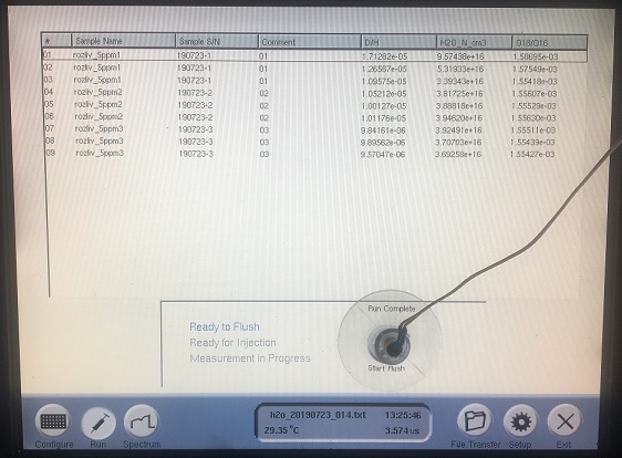
But you have to click something? Fortunately, the analyzer had a USB port and enough uncircumcised RedHat bottling at the beginning of 2000 to hook automatically into that port. It is for emulating the mouse on the new main board of the autosampler that the Arduino Pro Micro stands. it receives a PIN from NANO at the moment when the analyzer needs to be clicked. It was too lazy to write movement, because before starting work, the mouse must be set on the button in advance.
O HAPPINESS, that weighed down by experience, I unleashed the mouse part from the other managerial galvanic, cheap penny optron. BECAUSE at the end of the second day of debugging in kind, when everything was already working and I set up the beeper to deliver sounds similar to the original ones, one of the drivers released magical smoke and connected the 12v power section to the 5v logical one. Well, nothing, half a day of replacing it with one extracted from a bottomless bedside table is not a $ 100k analyzer repair. True, it later turned out that the new REXANT PSU purchased instead of a forgotten house at some point began to produce almost 50 instead of 12v, which caused an unfortunate delay.
Part Three, Calibration and Reliability Test
After assembly and initial debugging, the problem of position counting by the actual location of the vial arose. I had to make a keyboard and write a simple interface to it in the series. There were no ports at all, but for the most extreme case pins responsible for i2c were stored. They would be hung on the PCF8574 folk extender with micro-buttons that can be pulled up to the plus, which can be used to move the XY, select a step multiplier to speed up the process and change XY to ZP. After each click in the series displays a new position. Thanks to this simple technique, we were able to quickly and accurately get all the current coordinates and increments. Outside the calibration procedure, the mode selector switches and the button for starting the cyclogram are set up on the expander inputs. In the video, approximately in the middle, both buttons and toggle switches are visible.
Syringes for sample delivery are not cheap - $ 100 apiece. An error in positioning costs a bent needle and an irrevocably screwed syringe. Therefore, a broken syringe with a glued sewing needle was inserted and the machine was threshed at four points on a sheet of paper for almost half a day in order to identify alleged positioning failures. But they were not there, I was even surprised. However, since there is enough time between sample stabbing and recruiting a new one, I used it to search for zeros, just in case. In the video, this moment is seen closer to the end of the video.
Epilogue
In general, it was more likely successful. Two weeks passed from understanding hopelessness to transferring to production. Operated since the end of May, produces up to 200 measurements per day. The colleague in charge of sampling and measuring does not complain.
Cherries for the cake were new features that were not in the original. Ability to move on XY at the same time. The ability to double-pin the sample, which increased the sensitivity of the analyzer at ultra-low concentrations of the measured substance in the sample. Automatic parking after measurement.
PostScriptum
At the request of those interested, a video.