We begin to disassemble the software component of the MIRO platform. Let's see how to “cook” ARDUINO UNO using ESP8266 for firmware and wireless communication.
Table of Contents: Part 1 , Part 2 , Part 3 , Part 4 .
I didn’t want us to develop anything for the ESP8266. I was sure that for a long time there was a turnkey solution with the functionality I needed. And for MIRO, this functionality was quite simple:
- The software must have a web interface for network configuration;
- The software should implement ATMEGA328 wireless firmware;
- The software must have WiFi-UART bridge functionality for wireless debugging and management.
 Probably, for most of these functions, there is a well - known ESP-LINK . And he is really powerful. We used it in several more projects as a bridge between different interfaces - very convenient. But here a few months ago, when we sat down to deal closely with this issue, it turned out that he was not flashing ARDUINO UNO. Everywhere they write that it is flashing, but he did not flashing. And at that moment I didn’t even deeply understand why and what is the standard procedure. My comrades and I simply configured a virtual COM port on the host at a specific ESP IP address, indicated the reset line in ESP-LINK itself and tried to flash it. The ATMEGA328 reset was successful, but the firmware was not flooded. Moreover, the network has a bunch of lessons on organizing such firmware with ESP-LINK. But if you read their issue, then they always have something there that someone is not flashing.
Disappointed, he began to look for alternatives. And I found it as a fork of the original Arduino WiFi on GitHub from a developer with the nickname jandrassy.
Back in February of that year, there was a monstrous instruction in README to configure everything from the firmware to the development environment, but now it has been greatly simplified. Nevertheless, it still takes a little effort to set up the environment. However, the ARDUINO firmware is perfect. It is checked both from Windows and from Linux (on MacOS we seem to have never tested anything at all - no one in the immediate environment of the project has it).
The order of preparing the environment there is as follows:
- Download and install the dfu library from here ;
- By default, in this library (in the esp8266-serial-arduinouno-hacked.cpp file) it is declared that the ATMEGA328 chip's Reset line is connected to the GPIO5 ESP8266 line. For MIRO, you need to make changes here - change to GPIO2.
What exactly to change
It was:
It became:
esp8266_serial_arduinouno_hacked_target_reset(struct dfu_interface *iface) { pinMode(5, OUTPUT); digitalWrite(5, 0); delay(1); digitalWrite(5, 1); delay(200); return 0; }
It became:
esp8266_serial_arduinouno_hacked_target_reset(struct dfu_interface *iface) { pinMode(2, OUTPUT); digitalWrite(2, 0); delay(1); digitalWrite(2, 1); delay(200); return 0; }
The author of jandrassy, indicates that its implementation only works with this configuration of the target chip and bootloader (ATMEGA328P with Optiboot).
I am sure that there are still solutions and possibly even better ones. If someone knows for sure the working options, let me know. Because, despite the large number of ready-made code, we checked in addition to ESP-LINK another 2 or 3 projects - they did not work. In some cases, the firmware went through once, in some cases it did not work at all.
Perhaps one of the main advantages of the solution found is the relatively small code base of the project and the fact that the firmware for Arduino Core is developed.
What was not in the jandrassy project was the WiFi-UART wireless bridge. Already in the original Arduino.org WiFi Link firmware, a page with a terminal window was cut, allowing through the browser to work with the UART chip ATMEGA328. Just like this can be done in ESP-LINK. And if we turn to the first publications about Arduino UNO WiFi (for example, here it is ), it is clear that in the first versions of the firmware both the window and the corresponding menu item (“WiFi Console”) are. And even in release 1.0.0 in the archive, the console.js file (it just implemented this page) lies, but in fact it is not involved in the server in any way (we checked). Why and why they sawed it out is not clear.
I had to finish something. Now there is another server in the firmware - TELNET on the obvious port 23, with which many terminal programs work without problems.
However, at the moment, in order for everything to work, I had to remove from the jandrassy code the part responsible for the wireless firmware of the ESP itself. In the initial requirements, I did not have this functionality, so okay. However, if readers in the comments can affirmatively tell me whether it is possible in one firmware to implement the possibility of wireless firmware of both the ESP8266 itself and the “external” MCU (in this case, ATMEGA328), then I will think about returning this feature to the ESP firmware. Already during the preparation of the article, indirectly, I saw confirmation of this in this draft of Canadians. But did not check.
In the meantime, ESP is flashed exclusively via wire, but ARDUINO has the ability to both wireless firmware and TELNET communications via WiFi-UART bridge. And it is very convenient! My goal is achieved.
Well, in the project, as in the original, there is a WEB-interface for settings (pictures are clickable).

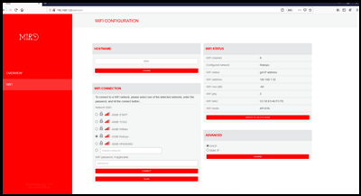
We changed the CSS files of the WEB-interface styles for our project and introduced a small “crutch” - now ESP is always in AP + STA mode. This crutch was made in order to exclude the possibility of switching the ESP to “only STA” mode, in which when transferring the robot to another subnet, the user loses the ability to configure the robot in a new network - the robot cannot connect to the new network, but there is no external access either - I have to reflash the ESP. In AP + STA mode, the user can always connect to the access point of the robot and configure the connection to the new WiFi network.
About how to flash ESP8266 with this "monster". In general, for an arbitrary module on an ESP8266 chip, the order is as follows:
- Turn on the board (connect to usb);
- Set the board parameters as in the figure;
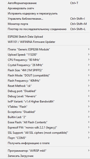
It is very important to select “v1.4 Higher Bandwidth” - if you select “v2”, then after the firmware it is not possible to connect to the board via WiFi (the access point is visible, but the connection procedure does not work - who knows what this is connected with - write in the comments). - Select a port (in the example in the screenshot - COM3).
- Run firmware. During the procedure of loading the board, the microcontroller’s memory is erased first, and then the firmware is erased.
- After completing the firmware procedure, you need to reset the board using the reset button.
- Select Arduino IDE ESP8266 Sketch Data Upload from the menu and download SPIFFS.
- Reset the board.
For the configuration with our “modified board” UNO + WiFi (see the first part ), everything is a little more complicated due to the hardware features of the board, which is difficult to comfortably study due to the large number of errors in the document with the circuit diagram. We wrote more detailed instructions in the repository's “MIRO ESP Firmware upload manual” file - if you act strictly on it, the firmware passes 100 out of 100.
We come to a very interesting part - the MIRO software component assigned to ATMEGA328. There is more work and space for discussion of various solutions, too.
Thanks to all!