8. We control from the phone-ROS Control, GPS-node
7. Robot localization: gmapping, AMCL, reference points on the room map
6. Odometry with wheel encoders, room map, lidar
5. We work in rviz and gazebo: xacro, new sensors.
4. Create a robot simulation using the rviz and gazebo editors.
3. Accelerate, change the camera, fix the gait
2. Software
1. Iron
Last time, after installing the budget lidar RPlidar-A1, we managed to build a room map, work with odometry. However, the robot, despite having a card and adjusting odometry from optical sensors, still feels insecure in the environment.
Rather, he does not see her at all. And he rides along the finished map far and wide, obstacles are not for him. This is both pleasing and distressing at the same time. On the one hand, don’t worry about obstacles and travel wherever your heart desires, on the other hand, it’s unlikely to go to another room or to the kitchen. Therefore, we will talk about the localization of the robot in space, using the algorithms that ROS provides, as well as our gentleman's set of lidar and encoders. But before we go directly to localization, let's talk about another ROS package, which also allows you to build 2D maps of the room and sometimes it works better than the ROS package from the previous post. Get to know gmapping.
Rm clan gmapping
We will not be originals and we will use developments from the already existing Habr article on the topic, but we will expand, update and deepen the information contained in it. The article is called Building a Map and Localizing a Mobile Robot in ROS without Odometry Using Laser_scan_matcher .
Part of the manipulations (highly loaded applications - rviz) will be performed on the Computer (outside the robot), the rest (motion driver, lidar launch node) - on the Robot.
First, according to the scenario of the above article, install laser_scan_matcher for ROS-kinetic on the Computer (the article was indigo):
sudo apt-get install ros-kinetic-laser-scan-matcher
Now run.
Nod with a lidar on the Robot:
roslaunch rplidar_ros rplidar.launch
On the computer:
roslaunch laser_scan_matcher demo.launch
* There is no need to run roscore, since the master node starts every time the Robot loads.
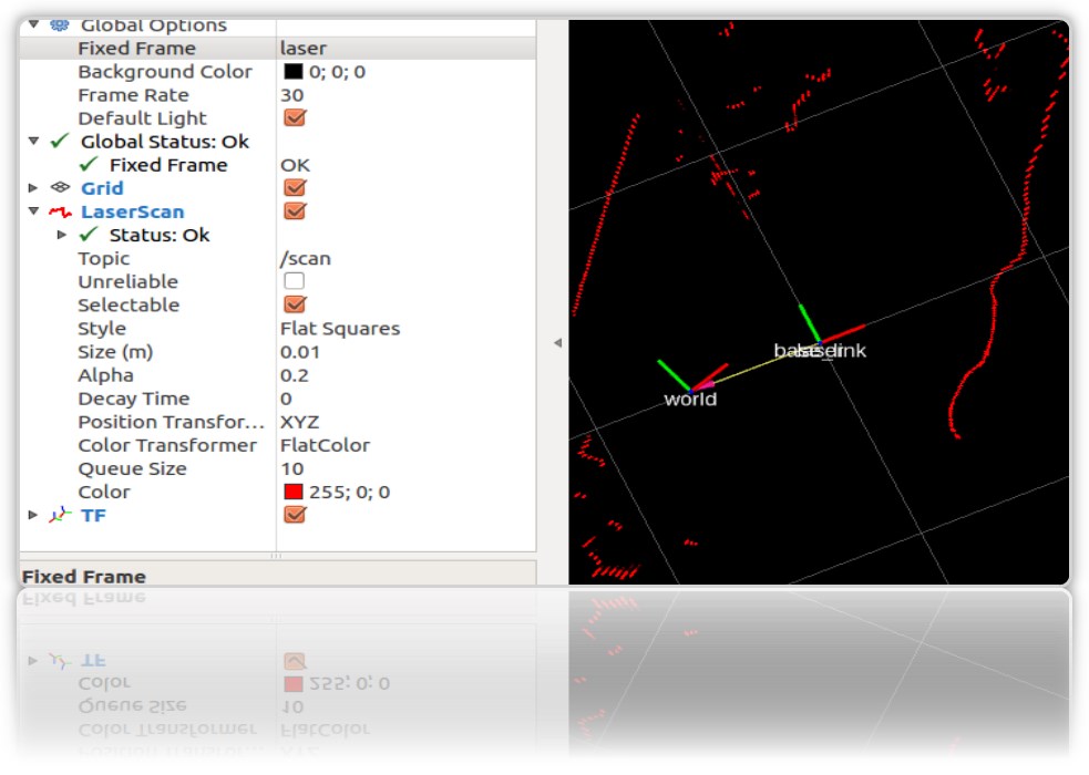
In the starting rviz, the contours of the room and the garbage in it will be visible:
we will need laser_scan_matcher to work with the gmapping ROS package. There is no need to install gmapping itself, it is already on the virtual machine as part of ROS Kinetic. Check the package in the system:

Now let's create a launch file using gmapping on the Computer (not on the Robot), as in the above article,:
roscd roscd rosbots_description/launch nano my_gmapping_launch.launch
the code
<?xml version="1.0"?> <launch> <node pkg="tf" type="static_transform_publisher" name="base_link_to_laser" args="0.0 0.0 0.0 0.0 0.0 0.0 /base_link /laser 40" /> <node pkg="laser_scan_matcher" type="laser_scan_matcher_node" name="laser_scan_matcher_node" output="screen"> <param name="fixed_frame" value = "odom"/> <param name="use_odom" value="true"/> <param name="publish_odom" value = "true"/> <param name="use_alpha_beta" value="true"/> <param name="max_iterations" value="10"/> </node> <node pkg="gmapping" type="slam_gmapping" name="slam_gmapping" output="screen"> <param name="map_udpate_interval" value="1.0"/> <param name="delta" value="0.02"/> </node> </launch>
As you can see from the code, the author starts 3 nodes: tf, laser_scan_matcher and gmapping.
Let's run the lidar on the Robot again:
roslaunch rplidar_ros rplidar.launch
On the Computer, the newly baked launch file and the rviz editor:
roslaunch rosbots_description my_gmapping_launch.launch
rosrun rviz rviz
In rviz we get a picture similar to the one that was obtained when building the map in our previous post about the Robot Trolley. Only this time the gmapping package works.
And I must admit, it does not work badly. If hector_slam left numerous artifacts on the map when the lidar rotated around its axis, this time there are almost no artifacts:
After traveling around the room, the constructed map is also saved:
rosrun map_server map_saver -f map-1
, where map-1 is the name of the map to save.
Localization with amcl
The algorithm that is used to determine the location of the robot on the map is called AMCL. AMCL uses a multi-particle filter to track the position of the robot on the map. In our robot, we use the ROS package (http://wiki.ros.org/amcl) to implement AMCL.
Run AMCL for our robot.
To do this, on the Computer in the project folder, create another launch file.
Let's call him
amcl-2.launch
<launch> <param name="/use_sim_time" value="false"/> <node pkg="tf" type="static_transform_publisher" name="base_link_to_laser" args="0.0 0.0 0.0 0.0 0.0 0.0 /base_link /laser 40" /> <node pkg="laser_scan_matcher" type="laser_scan_matcher_node" name="laser_scan_matcher_node" output="screen"> <param name="fixed_frame" value = "odom"/> <param name="use_alpha_beta" value="true"/> <param name="max_iterations" value="10"/> </node> <node name="map_server" pkg="map_server" type="map_server" args="/home/pi/catkin_ws/src/rosbots_description/maps/map-3.yaml"/> <node pkg="amcl" type="amcl" name="amcl" output="screen" > <!-- Publish scans from best pose at a max of 10 Hz --> <param name="odom_model_type" value="diff"/> <param name="odom_alpha5" value="0.1"/> <param name="transform_tolerance" value="0.2" /> <param name="gui_publish_rate" value="10.0"/> <param name="laser_max_beams" value="30"/> <param name="min_particles" value="500"/> <param name="max_particles" value="5000"/> <param name="kld_err" value="0.05"/> <param name="kld_z" value="0.99"/> <param name="odom_alpha1" value="0.2"/> <param name="odom_alpha2" value="0.2"/> <!-- laser, translation std dev, m --> <param name="laser_min_range" value="-1"/> <param name="laser_max_range" value="-1"/> <param name="odom_alpha3" value="0.8"/> <param name="odom_alpha4" value="0.2"/> <param name="laser_z_hit" value="0.5"/> <param name="laser_z_short" value="0.05"/> <param name="laser_z_max" value="0.05"/> <param name="laser_z_rand" value="0.5"/> <param name="laser_sigma_hit" value="0.2"/> <param name="laser_lambda_short" value="0.1"/> <param name="laser_lambda_short" value="0.1"/> <param name="laser_model_type" value="likelihood_field"/> <!-- <param name="laser_model_type" value="beam"/> --> <param name="laser_likelihood_max_dist" value="2.0"/> <param name="update_min_d" value="0.2"/> <param name="update_min_a" value="0.5"/> <param name="odom_frame_id" value="odom"/> <param name="base_frame_id" type="str" value="base_link" /> <param name="global_frame_id" type="str" value="map" /> <param name="resample_interval" value="1"/> <param name="transform_tolerance" value="0.1"/> <param name="recovery_alpha_slow" value="0.0"/> <param name="recovery_alpha_fast" value="0.0"/> <param name="use_map_topic" value="true" /> <param name="first_map_only" value="true" /> </node> </launch>
The code is completely identical to the already mentioned article, with the exception of:
- the node that launches the hokuyo lidar is excluded (it runs on the Robot)
- the path and name of the room map is different (map-3.yaml)
The code runs 4 nodes:
- tf
- map_server
- laser_scan_matcher
- amcl
The amcl node uses the map that map_server publishes for subsequent robot localization.
Run the launch files and look at the result.
But to Robot:
roslaunch rplidar_ros rplidar.launch
On the computer:
1st terminal:
roslaunch rosbots_description amcl-2.launch
2nd terminal:
roslaunch rosbots_description rviz.launch
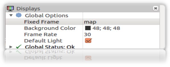
After rviz starts, the next steps in this editor will be the following:
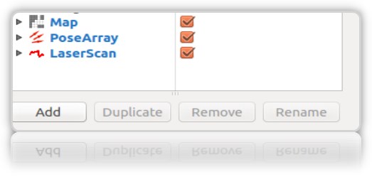
- add displays to rviz:
• LaserScan
• Map
• PoseArray
- localize the robot at the initial stage, since when starting amcl does not know where the robot started and where it is. Need “initial initialization”.
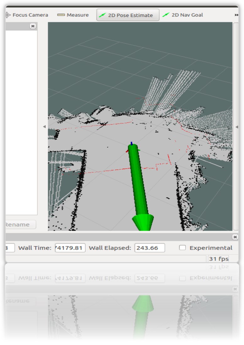
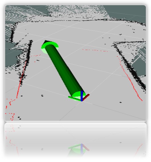
For this, in rviz you need to select "2D Pose Estimate" and the green arrow right in the window where the robot is shown indicate its position:
This operation must be done by selecting Frame "map" in rviz:
In the terminal we get the coordinates (pose) of the robot:
[ INFO] [1572374324.454855505]: Setting pose (1572374324.454806): -0.014 -0.012 0.655
You can set the position of the robot on the map using the green arrow on the map repeatedly.
It is desirable that the data from the lidar (red border) on the map coincide or be close to the actual location of the walls of the room:
In the rviz visualization window, we get the characteristic red arrows around the robot *:
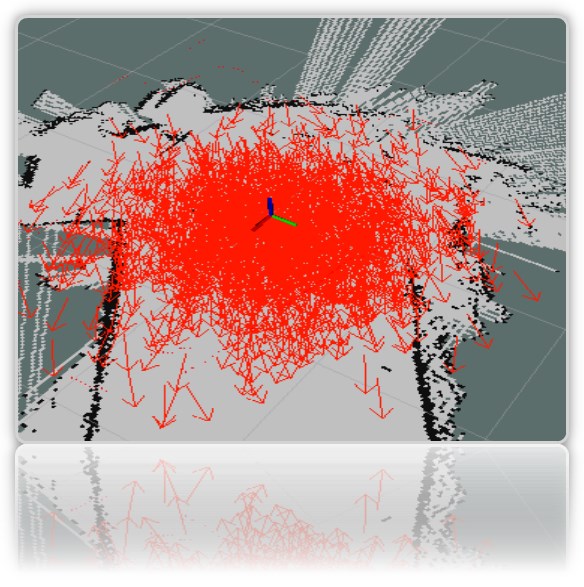
* as a robot, we have an axis for clarity (the entire painted rviz model is still hidden).
** If the arrows did not appear, then you can try to remove and re-check the PoseArray display added to rviz.
Despite the fact that we directly indicated on the map where the robot is located, the system still assumes that it can be in those places where the red arrows are drawn. This is the likely location of the robot on the map. A large number of arrows and their scatter on the map indicates that the system still does not know the exact location of the robot. However, the place where the shooter is denser, the robot is more likely.
In order for the system to more accurately understand exactly where the robot is, you need to ride on a map with running nodes that determine the location of the robot. We have from this set: lidar and encoders.
But we travel on the map only with the launched lidar, at the same time finding out whether it is possible to reliably localize the robot only with its (lidar) help.
-
ride a robot on a map
At work:
On the computer:
rosrun rosbots_driver part2_cmr.py
On the computer:
rosrun teleop_twist_keyboard teleop_twist_keyboard.py /cmd_vel:=/part2_cmr/cmd_vel
During the trip, amcl will start reading topics / scan, / map, / tf and publish the location of the robot in topics / amcl_pose and / particlecloud.
As you travel, you can observe that the number of arrows decreases and they are increasingly condensed at a point with the actual location of the robot:
The picture shows how the model travels (in the form of a tree of links). And it is also seen that the lidar does not accurately enough single-handedly cope with localization at ambiguous room boundaries.
What do the other parameters in the amcl node code mean?
Conventionally, they are divided into basic (General), filter parameters (Filter), Laser parameters (lidar) (Laser Parameters).
Main parameters:
- odom_model_type (default: "diff"): determines which odometry model to use. We have diff, which means differential. Can be changed to “omni,” “diff-corrected,” or “omni-corrected.”
- odom_frame_id (default: "odom"): defines the frame (read the topic) with which odometry will be associated. It is usually published in the odom topic.
- base_frame_id (default: "base_link"): frame for the base of the robot.
- global_frame_id (default: "map"): frame of the map, as a rule map-server publishes it to the topic map
- use_map_topic (default: false): determines whether the map will be loaded through the topic or by calling the service (we remember that in addition to topics in ROS there are also services and actions.
Filter Parameters
These options allow you to customize how the particle filter works.
- min_particles (default: 100): Sets the minimum number of particles for the filter. We have 500.
- max_particles (default: 5000): Sets the maximum number of particles for the filter.
- kld_err (default: 0.01): Sets the maximum allowable error between the true distribution and the calculated distribution. We have 0.05
- update_min_d (default: 0.2): Sets the linear distance (in meters) that the robot must travel in order to update the filter.
- update_min_a (default: pi / 6.0): Sets the angular distance (in radians) that the robot must move in order to update the filter. We have 0.5
- resample_interval (default: 2): Sets the number of filter updates needed before re-fetching. We have 1.
- transform_tolerance (default: 0.1): The time (in seconds) over which the published transformation should be dated to indicate that this transformation is valid in the future.
- gui_publish_rate (default: -1.0): The maximum speed (in Hz) at which scans and paths are published for visualization. If this value is -1.0, this function is disabled. We have 10.
Parameters of the laser (lidar) (Laser Parameters)
These parameters allow you to configure how amcl interacts with the lidar laser.
- laser_min_range (default: -1.0): The minimum scan range to consider; -1.0 will use the minimum range specified in the laser report.
- laser_max_range (default: -1.0): The maximum scanning range to consider; -1.0 will use the maximum laser range.
- laser_max_beams (default: 30): How many evenly distributed beams in each scan will be used when updating the filter.
- laser_z_hit (default: 0.95): The weights of the z_hit component of the robot model.
- laser_z_short (default: 0.1): The weights of the z_short component of the robot model.
- laser_z_max (default: 0.05): The weights of the z_max component of the robot model.
- laser_z_rand (default: 0.05): The weights of the z_rand component of the robot model.
Let's see what the min_particles and max_particles parameters affect. If you reduce their values, then when you launch the launch file, the number of particles in the visual editor will be clearly less.
All parameters carry a semantic load, but it is difficult to parse the effect of changing each of them within the article.
Reference points on the room map
The name is catchy and implies the position of the robot on the map at this particular moment.
What are they needed for? In order to understand that the robot came from point A in the room to point B in the kitchen.
Data on the position of the (pose) of the robot can be obtained with the amcl working node (what started in the article above).
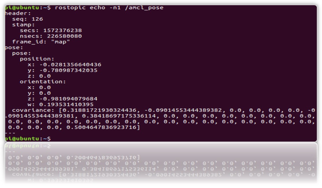
And look in the topic / amcl_pose:
rostopic echo -n1 /amcl_pose
* key n1 - for "fixing" the flow of messages in the topic.
Let's create a service that, when called, will give away the position (coordinates) of the robot so that each time it does not look into the topic.
1.Create a new ros package.
cd catkin_ws/src catkin_create_pkg get_pose rospy cd get_pose/src
2. In the folder, create a file:
get_pose_service.py
#! /usr/bin/env python import rospy from std_srvs.srv import Empty, EmptyResponse # Import the service message python classes generated from Empty.srv. from geometry_msgs.msg import PoseWithCovarianceStamped, Pose robot_pose = Pose() def service_callback(request): print "Robot Pose:" print robot_pose return EmptyResponse() # the service Response class, in this case EmptyResponse def sub_callback(msg): global robot_pose robot_pose = msg.pose.pose rospy.init_node('service_server') my_service = rospy.Service('/get_pose_service', Empty , service_callback) # create the Service called get_pose_service with the defined callback sub_pose = rospy.Subscriber('/amcl_pose', PoseWithCovarianceStamped, sub_callback) rospy.spin() # mantain the service open.
* Do not forget to make it executable chmod + x get_pose_service.py
3. Let's create launch for the file with the node code:
cd .. mkdir launch && cd launch
nano
get_pose_service.launch
<launch> <node pkg="get_pose" type="get_pose_service.py" name="service_server" output="screen"> </node> </launch>
4.Do not forget to rebuild catkin:
cd catkin_ws catkin_make
Now we will restart everything, including the new launch file.
But to Robot:
roslaunch rplidar_ros rplidar.launch
On the computer:
1- : roslaunch rosbots_description amcl-2.launch 2- : roslaunch rosbots_description rviz.launch 3- : roslaunch get_pose get_pose_service.launch
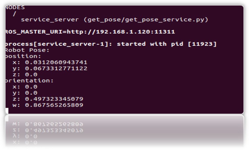
We turn to the new service, which should give us the current position of the robot on the map (call the ROS service):
rosservice call /get_pose_service
In the terminal running launch get_pose, we’ll get the coordinates of the robot on the map:
Possible mistakes.
[rviz.launch] is neither a launch file in package [rosbots_description] nor is [rosbots_description] a launch file name
decision:
cd catkin_ws source devel/setup.bash