Part 2 <- Part 1
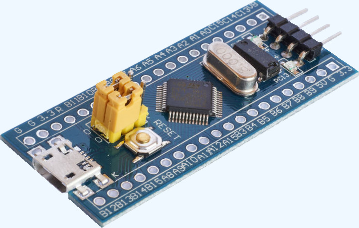
Let's continue to experiment with the STM32F103C8T6 microcontroller, connect some I2C sensors / displays to the “blue tablet”.
Implemented support for popular I2C displays:
- LCD 1602
- SSD1306
Implemented support for the following sensors:
- BH1750 - Light Sensor
- BME280 - temperature, pressure, humidity sensor
- CCS811 - CO2 sensor, VOC (Volatile Organic Substances)
In order to start working with new features, you need to create a new project.
The link to download the MIOC program is given in the first part.
Sensors
BH1750 sensor
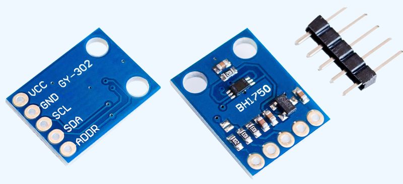
BH1750 16-bit light sensor (light meter) with I2C interface. The photodiode on the BH1750 determines the intensity of the light, which is converted to the output voltage using an operational amplifier. Built-in ADC provides 16-bit digital data. The internal logic of the BH1750 eliminates the need for any complex calculations, since it directly outputs significant digital data in lux (lux).
According to the documentation, the BH1750 sensor is sensitive to visible light and is practically not affected by infrared radiation, i.e. reacts to approximately the same spectral range as the human eye.
To work with this sensor, on the “Configuration” tab, select BH1750.
The measurement results will be in the global variable:
uint32_t BH_L;
Connecting the sensor to the I2C2 bus:
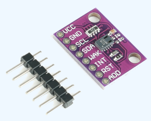
BME280 Sensor
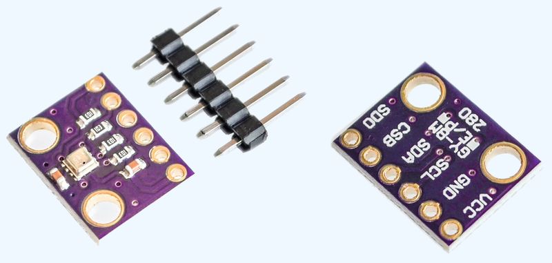
This sensor measures the environmental parameters: temperature, atmospheric pressure, as well as air humidity.
There is also a similar sensor - BMP280, which lacks the ability to measure humidity. But it costs a lot less.
In addition to the fact that the sensor measures all of the above parameters, it also knows how to filter noise, calibration of readings is built into it. Also, unlike other sensors, this sensor makes all these measurements not only quickly, but also in wider ranges. For example, many sensors cannot measure air humidity below 20 percent.
The declared characteristics of the sensor are as follows:
The sensors are connected to the I2C2 bus as follows:
If BMP280 will be used, then in the main / bme280.c file you need to comment out all lines marked // Comment for BMP.
The measurement results will be in global variables:
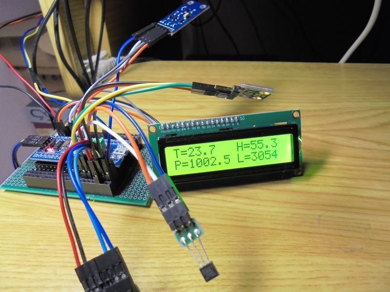
An example of a program working with BH1750, BME280 sensors, and a 1602 display:
#include "mx_init_hw.c" int main() { char s[64]; float t=0, p=0, h=0; Init_HW(); // --------------------- // The main program loop // --------------------- while( TRUE ) { delay_ms( 300 ); t = BME_T / 10.0; p = BME_P / 100.0; h = BME_H / 10.0; sprintf( s, "t=%-7.1fC", t ); SSD1306_write_string( 1, s ); sprintf( s, "p=%-7.1fPa", p ); SSD1306_write_string( 2, s ); sprintf( s, "h=%-7.1f%% ", h ); SSD1306_write_string( 3, s ); sprintf( s, "T=%-7.1fH=%.1f", t, h ); LCD_write_string( 1, s ); sprintf( s, "P=%-7.1fL=%u", p, BH_L ); LCD_write_string( 2, s ); } }
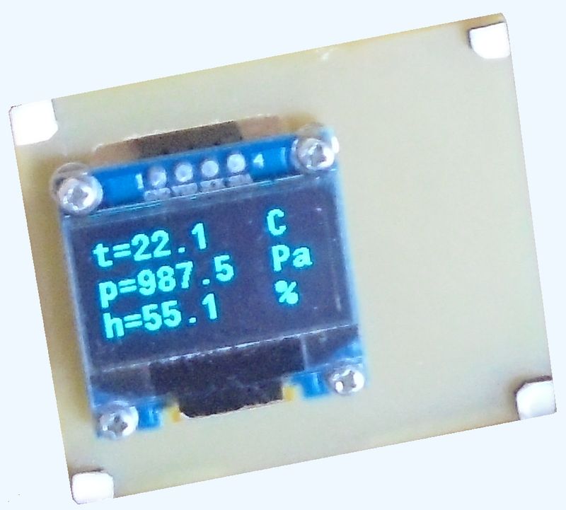
The result of the program:
The same program will display temperature, pressure, humidity on the display of the SSD1306
(connect this display, and select it in the configuration):
The BME280 can measure temperature with greater accuracy. To do this, it must be calibrated. In the main / bme280.h file, there is a macro definition for this:
#define DT 3520
CCS811 Sensor
The air around us is a mixture of gases and consists mainly of nitrogen (about 78%) and oxygen (about 21%). The remaining percentage is accounted for by various impurities (inert gases, carbon dioxide, carbon monoxide, organic volatile substances (VOC), etc.). Despite the fact that the percentage of impurities is small, a change in their concentration can be very unpleasant and even dangerous for humans. Air quality in office and residential premises is most often associated with the content of CO2 and VOC.
Organic volatile substances include more than 5000 compounds. The formation of most of them is somehow connected with the processes of human life.
Thus, even a simple human presence in a closed room leads to "pollution" of the air and the need for ventilation. Estimating the concentration of VOCs in the air is difficult. Previously, CO2 sensors were used to assess VOC concentrations. In this case, the fact was taken into account that under normal conditions, the concentrations of VOC and CO2 are bound. Knowing the percentage of CO2, one can indirectly determine the concentration of VOCs. If the content of carbon dioxide in the air has reached a certain limit, ventilation must be turned on.
In practice, the relationship between VOC and CO2 is not always straightforward. For example, indoor smoking causes a sharp jump in the VOC content, which CO2 sensors do not record, so the carbon dioxide concentration does not change much. Carbon dioxide sensors will also be powerless if household chemicals, cleaning products, paints and varnishes are used in the room. AMS offers its solution to the problem of measuring VOC concentration - CCS811 sensors.
Features of CCS811B Air Quality Sensors:
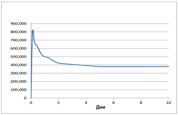
The sensor has an automatic calibration algorithm. Measured values are automatically set within a few days. For this reason, the new sensor has a gigantic initial error and must work out for at least three to four days until more or less reliable results are obtained:
The user also needs to remember that each time after switching on, the CCS811 sensor must “warm up”. The time of such a “warm-up” is more than 30 minutes, during which the error is unacceptably large:
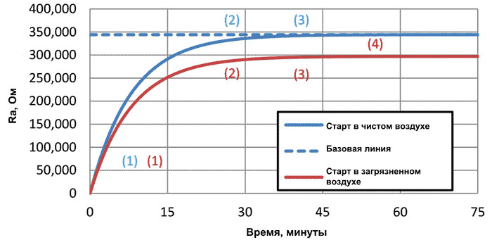
This feature of CCS811 is extremely important to consider.
Sensor measurement results are in global variables:
uint32_t CCS_CO2;
uint32_t CCS_TVOC;
Connecting the sensor to the I2C2 bus:
You can write a program for printing the results of this sensor using the examples above and the description of working with the console in the first part yourself.
Examples of other sensors
HC-SR501 motion sensor
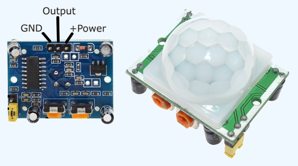
Some sensors, such as the HC-SR501 motion sensors, do not require writing any additional snippets.
For this sensor, declare a variable, select Type = GPIO_Mode_IN_FLOATING, select a port.
Generate BSP, compile, upload to MK. Next, we work with this sensor in the same way as with the button (to receive data).
HC-SR501 Sensor Connection:
Temperature / Humidity Sensor DHT22
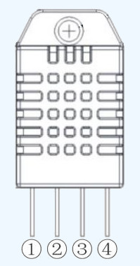
Temperature / Humidity Sensor
Sensor Connection:
Working with this sensor will be an example of a custom snippet (analogue to the arduino sketch).
Snippet can be taken here:
dht22.c
Put it in the main folder
In this file, edit the lines:
#define PORT GPIOA #define PIN GPIO_Pin_5
by actual sensor connection
The text of the program for working with this snippet:
#include "mx_init_hw.c" #include "dht_22.c" int main() { int16_t dht_t, dht_h; Init_HW(); dht_init(); // --------------------- // The main program loop // --------------------- while( TRUE ) { delay_ms( 5000 ); if( !get_dht_data( &dht_t, &dht_h ) ) print( "t=%.1f h=%.1f\r\n", (float)dht_t / 10.0, (float)dht_h / 10.0 ) else print( "DHT 22 - ERR\r\n" ); } }
The result of work:
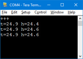
More often than every 4-5 seconds, the sensor does not make sense to interrogate. Reasons: temperature calculation takes place within 800-900 mS, second: if you interview more often, the sensor self-heats up.
CLI
The firmware contains a small shell that works with the console. You can see what commands are in the main / mx_cli.c file
If desired, you can add any of your teams.
The CLI starts working in No Echo mode, that is, the characters you enter are not displayed. To display the characters you enter, type: echo on.
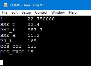
The “sh on” command will output twice a second the values of the variables declared in the configurator and the variables associated with the sensors. The number in the first position corresponds to the line number in the configurator table. This command is made to transfer data to a system connected to the console.
There are no flags and mutexes that analyze the console’s busyness. Therefore, when using the “print” and “echo on” operator together, mixing of the output information may occur. You should not use both methods at the same time. To solve this problem, you can use two output channels. For example, the console is on UART1, and the output of user information on VCP. Or vice versa.
Use functions:
send_uart1( char *data, int len ) send_usb( char *data, int len )
To facilitate the use of these functions, you can change the printf macro in the gbl.h file. For example, the following:
#define printf(fmt,argv...){char s[128];sprintf(s,fmt,##argv);send_usb(s,strlen(s));} // VCP
Example output to the console (echo on):
I2Cx bus scan
To scan the I2C1 or I2C2 bus, there are ready-made "firmware" * .hex
scanner I2Cx
Information output to UART1, speed - 115200.8, N, 1
After loading the scanner, press the “Reset” button.
The firmware shows the addresses of the devices found on the bus.
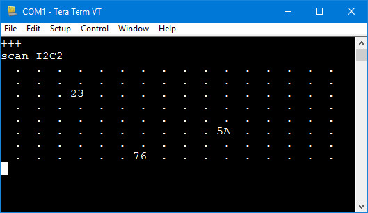
All three connected sensors described above.