Autonomous weather station on the ATMEGA328P controller and battery powered with a wireless remote sensor
Improving my room thermostat, which I wrote about earlier , I set out to supplement it with a wireless temperature sensor for measuring outdoor air temperature, assemble a battery-powered thermostat and replace the RF 433MHz transmitter-receiver modules with another pair of radio modules with a longer communication range at a supply voltage not more than 3V. In the course of solving these problems, an autonomous weather station emerged, which will be discussed below.

The weather station consists of two nodes, let's call them an analyzer and a thermometer for simplicity. Communication between nodes - wireless, over the air.
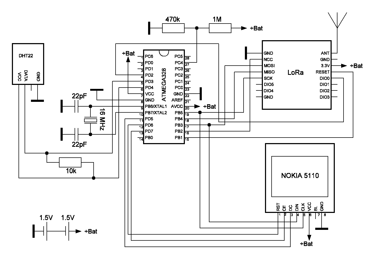
The analyzer, built on the ATMEGA328P controller, measures the temperature and humidity in the room (temperature and humidity sensor DHT22) and the power supply voltage of the analyzer, which is provided by two AA 1.5V batteries. The controller receives a signal from the LoRa receiver, which receives information from the thermometer (remote sensor) over the air. Information from the controller is displayed on the LCD of the NOKIA 5110.
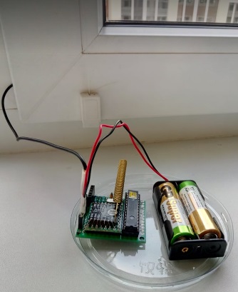
The thermometer, also assembled on the ATMEGA328P controller, measures the outdoor air temperature (DS18B20 temperature sensor) and the supply voltage of the remote unit, organized on two 1.5V AA batteries. The LoRa transmitter of this unit transfers the temperature and supply voltage to the analyzer.
The ATMEGA328P controller and the LoRa transmitter of the thermometer are put to sleep mode to save battery power after measurements and send information. The power supply voltage to the DS18B20 sensor is applied programmatically only for the duration of the temperature measurement. Measuring and sending data from the thermometer is performed with a period of about one minute.
In the same work-sleep mode, the analyzer also works. The duration of the controller and receiver analyzer is slightly more than one minute (about 65 seconds). This is done to confidently receive the signal from the thermometer - after all, the operation of the thermometer and the analyzer are not synchronized. Then the ATMEGA328P and the LoRa receiver are put into sleep mode for 14 minutes before waking up and starting the next cycle. DHT22 only provides power during measurement.
To program sleep mode of the ATMEGA328P controllers, the LowPower.h library is used.
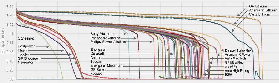
With the discharge of the batteries, the voltage decreases.
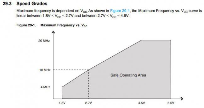
The lower limit of the operating voltage for the ATMEGA328P controller is 1.8V. At the same time, the factory setting of the fuse ATMEGA328P was performed to monitor the threshold voltage of 2.7V, so it is necessary to change the factory settings of the fuse to monitor the threshold of 1.8V, to guarantee the operation of the controller with a voltage below 2.7V when powered by batteries.
The controller’s internal oscillator may not start at a frequency of 16 MHz with a supply voltage of 3 V or slightly lower. Both of my controllers work with 16 MHz quartz at a reduced supply voltage of 2.7 ... 2.8 V, so I did not change the 16 MHz quartz to 8 MHz.
To assemble the device, you will need components, a list of which and their estimated cost at AliExpress website prices are shown in the table.
| Component | Price, $ |
| analyzer | |
| ATMEGA328P-PU Controller | 1,59 |
| Temperature and humidity sensor DHT22 | 2,34 |
| LoRa Ra-01 Transmitter | 3.95 |
| LCD NOKIA 5110 | 1.91 |
| Development board (mounting) board, mounting wires, AA batteries, 16 MHz (8 MHz) quartz resonator, resistors, etc. | 4.00 |
| thermometer | |
| ATMEGA328P-PU Controller | 1,59 |
| DS18B20 temperature sensor | 0.63 |
| LoRa Ra-01 Transmitter | 3.95 |
| Development board (fiberglass), mounting wires, AA batteries, 16 MHz (8 MHz) quartz resonator, resistors, etc. | 4.00 |
| Total (approximately): | 24 |
Analyzer

The analyzer brain is an ATMEGA328P controller. It receives signals from the DHT22 sensor and, through the SPI protocol, communicates with the LoRa receiver and the NOKIA 5110 display.
There are many complaints on the Internet about the low accuracy of the DHT22. Today there is an alternative: more modern temperature and humidity sensors HTU21 (GY21) , (Vcc = 3 ... 5 V), Si7021 , (Vcc = 1.9 ... 3.6 V), SHT21 , (Vcc = 2.1 .... 3.6 V).
I use DHT22, since the discrepancy between the humidity readings of my specimen of this sensor and the commercially available LaCrosse WS-9024IT thermo-hygrometer is not more than 8 units, which is quite acceptable for domestic purposes. The discrepancy between the humidity readings increases greatly if the DHT22 supply voltage is below 3V. This is understandable, because the supply voltage of DHT22 should be within 3 ... 5V. Summing up - ideally in these conditions, the Si7021 sensor fits into the analyzer circuit .
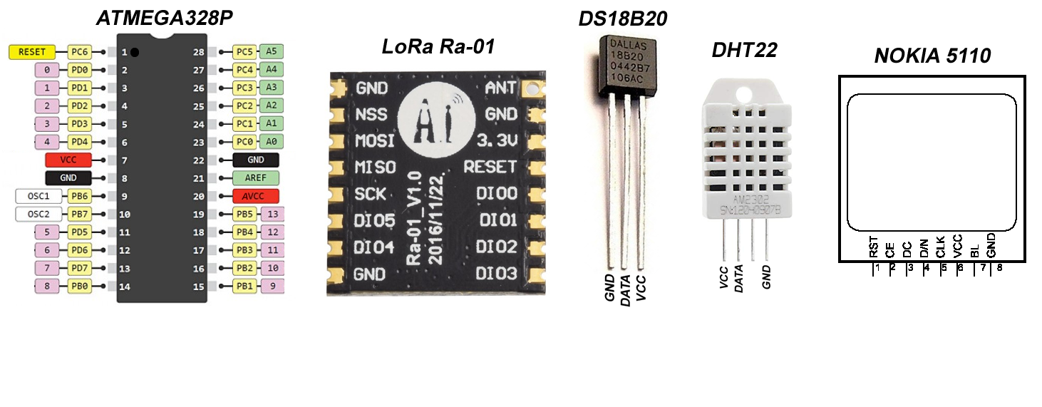
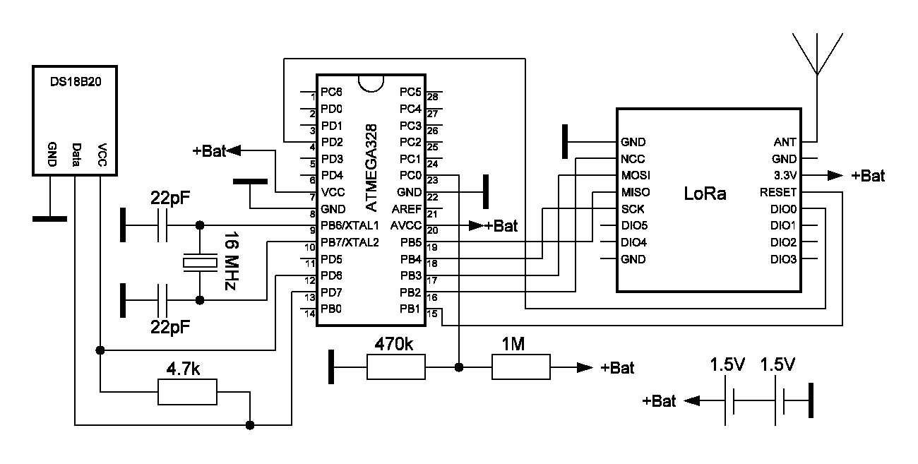
In the picture below - the pinout of the elements of the weather station.
Fusion and much more of various controllers, including ATMEGA328P, can be read and edited with the SinaProg utility. If this is your first time encountering this program, then despite the intuitive interface, do not try to start working with it after installing the application. First read this article in which HWman provides the necessary SinaProg add-ons when using the Arduino UNO board as a bootloader.
I advise you to first read the factory settings of the fusion ATMEGA328P and save their values in order to return to them in case of failure. In my controllers, the factory settings for the fuse bit are: LOW: 0xFF, HIGH: 0xDE, EXTENDED: 0x05 (Vcc = 2.7V, BODLEVEL = 101). New fuses for monitoring the 1.8V threshold that you want to set: LOW: 0xFF, HIGH: 0xDE, EXTENDED: 0x06 (Vcc = 1.8V, BODLEVEL = 110).
The analyzer sketch for loading in the ATMEGA328P is under the spoiler.
/* * ATMEGA328P , */ #include <SPI.h> #include <LoRa.h> #include "DHT.h" #define DHTPIN 3 // what digital pin we're connected to #define DHTTYPE DHT22 // DHT 22 (AM2302), AM2321 DHT dht(DHTPIN, DHTTYPE); float Tin=0; int Hin=0; float BatteryInLevel; // String LoRaData, Tout_str, BatteryInLevel_str, BatteryOutLevel_str; //sleep #include <LowPower.h> #define PowerDHT (4) // DHT22 unsigned int sleepCounter; //Nokia 5110 #include <SPI.h> #include <Adafruit_GFX.h> //https://esp8266.ru/forum/threads/esp8266-5110-nokia-lcd.1143/#post-16942 #include <Adafruit_PCD8544.h> //https://esp8266.ru/forum/threads/esp8266-5110-nokia-lcd.1143/#post-16942 //timer #include <SimpleTimer.h> SimpleTimer timer; Adafruit_PCD8544 display = Adafruit_PCD8544(5, 7, 6); void sendSensor(){ digitalWrite(PowerDHT, 1); delay (2000); Hin = dht.readHumidity(); Tin = dht.readTemperature(); /* if (isnan(Hin) || isnan(Tin)) { // Serial.println("Failed to read from DHT sensor!"); return; }*/ digitalWrite(PowerDHT, 0); // : analogReference(INTERNAL); int sensorValue = analogRead(A4); BatteryInLevel = (sensorValue * 3.2 / 1024); } void draw(){ display.clearDisplay(); //Tin { display.setTextSize(2); display.setCursor(8,0); display.println (Tin, 1); // display.setCursor(68,0); display.println("C"); } //Hin { display.setTextSize(2); display.setCursor(8,16); display.println(String(Hin)+ "%"); } //Tout { char chr_Tout [12]; Tout_str.toCharArray(chr_Tout, 5); display.setTextSize(1); display.setCursor(50,16); display.println(String(chr_Tout)+"C"); } // Battery Out Level { char chr_BatteryOutLevel [12]; BatteryOutLevel_str.toCharArray(chr_BatteryOutLevel, 4); display.setTextSize(1); display.setCursor(2,32); display.println("BAT Out: " + String(chr_BatteryOutLevel)+"V"); } // Battery In Level { display.setTextSize(1); display.setCursor(2,40); display.println("BAT In: "); display.setCursor(56,40); display.println(BatteryInLevel, 1); // display.setCursor(74,40); display.println("V"); } display.display(); /* Serial.println("Tin: " + String(Tin)+"*C"); Serial.println("Hin: " + String(Hin)+"%"); Serial.println("Tout: " + String(Tout_str)+"*C"); Serial.println("BAT_In: " + String(BatteryInLevel)+"V"); Serial.println("BAT_Out: " + String(BatteryOutLevel_str)+"V"); Serial.println("......"); */ } void sleepDevice(){ // sleepCounter = 65 - 10 min // sleepCounter = 91 - 14 min for (sleepCounter = 91; sleepCounter > 0; sleepCounter--) //91!!! { LoRa.sleep (); LowPower.powerDown(SLEEP_8S, ADC_OFF, BOD_OFF); } LoRa.sleep (); } void SignalReception (){ // try to parse packet int packetSize = LoRa.parsePacket(); if (packetSize) { // read packet while (LoRa.available()) { LoRaData = LoRa.readString(); // Serial.println(": "+(LoRaData)); } int pos1 = LoRaData.indexOf('#'); Tout_str = LoRaData.substring(0, pos1); BatteryOutLevel_str = LoRaData.substring(pos1+1, LoRaData.length()); } } void setup() { // Serial.begin(9600); pinMode(PowerDHT, OUTPUT); // display.begin(); display.clearDisplay(); display.display(); display.setContrast(60); // display.clearDisplay(); display.setTextSize(2); display.setCursor(12,16); display.println (">>>>>"); // display.display(); dht.begin(); sendSensor(); draw(); while (!LoRa.begin(433E6)) { // Serial.println("."); delay(500); } // – «0-0xFF». LoRa.setSyncWord(0xF3); // Serial.println("LoRa Initializing"); timer.setInterval(20000, sendSensor); timer.setInterval(5000, draw); timer.setInterval(62000, sleepDevice); } void loop() { SignalReception(); timer.run(); }
To work with the ATMEGA328P controllers, I use the Arduino UNO board as a programmer. The process of installing the bootloader and downloading the sketches to the ATMEGA328 controller using the Arduino UNO board is described in detail here . There is a good video on Youtube on this topic .
The sketch commented out the commands for outputting to the serial port monitor (Serial). Uncomment if necessary.
The cycle begins by listening to the air and receiving information by the LoRa receiver. The timer sets the listening time - 62 seconds. At this time, the information on the NOKIA display is updated with a period of 5 seconds and, with a period of 20 seconds (3 times), the DHT22 sensor measures temperature, humidity, and the voltage level of the batteries through one of the controller's analog inputs. The supply voltage to the DHT22 is applied only during measurements with a minimum delay of 2 seconds, at which the sensor is still working. The output of the ADC in the sketch is scaled to the voltage of the new batteries, which is 3.2V (1.6V x 2). The listening time of the air was chosen slightly more than 1 min to confidently receive one packet from a thermometer that works on transmission with a period of 1 min, but more on that below. Then, at the 62nd second, the controller and receiver are put into sleep mode, which lasts about 14 minutes, i.e. the period of the “work / sleep” cycle of the analyzer is about 15 minutes. I note that the sleep mode in the analyzer is a forced measure designed to significantly reduce consumption. On the other hand, in 15 minutes the temperature and humidity will not change dramatically. As the calculation of the battery life showed, the sleep mode can be reduced to 8-9 minutes, but I did not do this, since in the future the unit will be supplemented with thermostat functions, which will lead to an increase in consumption.
For comparison, the table below shows the characteristics of the LaCrosse WS-9024IT thermohygrometer and the analyzer from this project. Most of the LaCrosse parameters from the table are not given in its technical description, but were measured. I wanted to supplement the table with the results of similar amateur developments, but, unfortunately, I did not find anything.
| Parameter | LaCrosse WS-9024IT | SadilTM |
| Food | 2xAA, 3B, Durasell | 2xAA, 3V, GP Ultra +, 2.72 Wh |
| Sleep consumption | 8 μA | 10 μA |
| Sleep duration | 14 min | |
| Operational consumption | 200 μA | 3 mA |
| Duration of work | 65 sec | |
| Work / Sleep Cycle Period | 30 sec | 15 minutes |
| Operating time | more than 2 years | about 1 year |
Calculation of working hours.
Average current consumption: 3 mA / 15 + 0.01 mA = 0.21 mA, where 15 is the duty cycle. GP Ultra + battery capacity in mA * hour: 2.72 W * hour / 1.5 V = 1.81 A * hour = 1800 mA * hour. Operating time: 1800 mA * hour / 0.21 mA = 8600 hours (11.9 months).
I will clarify:
- The calculation is very approximate, since the calculation is based on the maximum (peak) consumption of the analyzer.
- LaCrosse's operating hours are based on my own experience. I have had this device for a long time.
Thermometer

The capacity and voltage of batteries in cold weather are greatly reduced . Therefore, in order not to expose the batteries and the device as a whole to such strong tests, I took out only the DS18B20 temperature sensor outside the room, and the unit and batteries are in the room. The DS18B20 connects to the host board with a thin three-wire cable. I spotted this solution in my serial weather station - the developers are sure that there will always be a gap in the apartment for laying wires with a diameter of several millimeters.
The fuses for the ATMEGA328P thermometer are the same as for the analyzer.
The thermometer assembly is also built on the ATMEGA328P controller. It receives the signal from the DS18B20, measures the supply voltage and controls the LoRa transmitter.
The thermometer sketch is under the spoiler.
/* * ATMEGA328P , */ #include <OneWire.h> OneWire ds(7); //pin 13, Atmega328P #include <SPI.h> #include <LoRa.h> #include <LowPower.h> #define PowerDS18B20 (6) //pin 12 (Atmega328P), e DS18B20 unsigned int sleepCounter; // , float Tout; // int i; // (20 1 ) String messageTout; // LoRa- float batteryLevel; // const int batteryPin = A0; // pin 23 (Atmega328P), void Measurement (){ // byte data[2]; digitalWrite(PowerDS18B20, 1); ds.reset(); ds.write(0xCC); // (1 ) ds.write(0x44); // delay(700); ds.reset(); ds.write(0xCC); ds.write(0xBE); // data[0] = ds.read(); data[1] = ds.read(); Tout = ((data[1] << 8) | data[0]) * 0.0625; // Serial.println("Tout= "+ String(Tout)); digitalWrite(PowerDS18B20, 0); // : analogReference(INTERNAL); int sensorValue = analogRead(A0); batteryLevel = (sensorValue * 3.2 / 1024); // Serial.println("BAT= "+ String(batteryLevel)); } void SetSynchLoRa () { int counter = 0; while (!LoRa.begin(433E6) && counter < 10) { // Serial.print("."); counter++; delay(500); } /* if (counter == 10) { // Serial.println("Failed to initialize ..."); }*/ LoRa.setSyncWord(0xF3); } void SendMessage (){ // (, ) messageTout = String(Tout) + "#" + String(batteryLevel); // Serial.println(messageTout); delay(250); LoRa.beginPacket(); LoRa.print(messageTout); LoRa.endPacket(); } void setup() { // Serial.begin(9600); // Serial.println("Initializing ..."); pinMode(PowerDS18B20, OUTPUT); SetSynchLoRa (); } void loop() { // Serial.println(""); // Serial.println("i = " + String(i)); if (i >= 30){// i >= 30 (1 ) - (, - 1 /1 ) for (sleepCounter = 5; sleepCounter > 0; sleepCounter--) { LoRa.sleep (); LowPower.powerDown(SLEEP_8S, ADC_OFF, BOD_OFF); } Measurement (); SendMessage (); LoRa.sleep (); } else { // 1 , - 1 /2 Measurement (); SendMessage (); delay (1000); } i++; if (i >= 30) i = 30; // }
At first, when the power is connected, the thermometer operates in intensive mode for one minute. It measures the temperature, voltage of the batteries and sends their values on the air every 2 seconds. This is for convenience. Suppose you don’t have to wait a minute when replacing batteries or debugging. Information from the sensor will appear on the analyzer display in the first seconds after connecting the batteries of the thermometer and analyzer. Naturally, you should hurry up and not make a time gap for more than a minute between connecting the batteries on both nodes.
Then the remote sensor goes into normal mode. After measuring and sending information that lasts a little more than 1 second, the controller and transmitter are put into sleep mode for about 1 minute.
Calculation of working hours.
Average current consumption: 8 mA / 60 + 0.01 mA = 0.14 mA, where 60 is the duty cycle. GP Ultra + battery capacity, (mA * hour): 2.72 W * hour / 1.5 V = 1.813 A * hour = 1800 mA * hour. Operating time: 1800 mA * hour / 0.14 mA = 12800 hours (18 months).
Previous clarifications regarding the accuracy of the calculated operating time from one set of batteries remain valid.
And a comparison table. It contains the results of a couple of similar projects from the Internet.
| Parameter | LaCrosse WS-9024IT | maniacbug | avs24rus | SadilTM |
| Food | 2xAAA, 3B, Durasell | 3V, CR2450 Renata, 540 mAh | 3V, CR2450, 550-610 mAh | 2xAA, 3V, GP Ultra +, 2.72 Wh |
| Sleep consumption | 10 μA | 0.14 mA (?) | 14 μA | 10 μA |
| Sleep duration | 1 min | |||
| Operational consumption | 90 μA | 13.57 mA | 16 - 18 mA | 8 mA |
| Duration of work | 0.027 sec | 1 sec | ||
| Work / Sleep Cycle Period | 5 sec | 1 min | 10 min | 1 min |
| Operating time | more than 2 years | more than 0.5 years | about 1.5 years |
I can not help but mention one more work: Wireless temperature, humidity and atmospheric pressure sensor on nRF52832 , Berkseo . Everything in the sensor is striking in its completeness and thoughtfulness: minimal dimensions, housing design and even a slot in this housing for an indicator LED instead of the traditional round eye. In this style, all the projects of this author were completed - I counted them 12. The only drawback is the meager list of technical characteristics of the wireless sensor: the sensor is powered by CR2430 / CR2450 / CR2477 batteries, consumption in transmission mode is 8 mA, in sleep mode - 5 μA . This is clearly not enough to evaluate the duration of the sensor on a single battery. Although I understand him - he emphasized the design and design of the device.
If the nodes are assembled without errors, then on the display we will see the following picture:

From the comparative tables it can be seen that the operational consumption of amateur devices is two orders of magnitude higher (more than 100 times!) Than in the analogous functions of the industrial LaCrosse. For example, 8 mA versus 90 μA for the remote sensor and 3 mA versus 200 μA for the analyzer. Sleep consumption is approximately the same - about 10 μA. This striking difference in operational consumption is explained, in my opinion, by the fact that controllers in amateur circuits are programmed in the Arduino IDE language, and in industrial products - most likely in one of the low-level languages or C # / C. If you use the C programming language, then I’m sure you can reach a consumption comparable to industrial designs. However, this was very convincingly experimentally shown by HWman in his publication “ Why Many Don't Like Arduino ”. Performing the simplest sketch of up to a dozen lines (Blink), made in the Arduino language in one case and in another - C leads to a performance loss of 26 times. In short, increased resource consumption is a payment for comfort and a small effort on the part of the programmer - the rest will be done by the “gluttonous” functions of the development environment for him in Arduino. I anticipate having to strain and master C # / C ...
findings
• The assembled analyzer and thermometer have too much operational current consumption compared to industrial designs. To reduce power consumption, sleep mode has been entered in both nodes. You can significantly reduce operational consumption by rewriting the sketch in C # / C.
• A third suggests itself for two batteries in the circuits, then the following problems are automatically solved: there is no need to reinstall the fuse, stable operation of the controller at a frequency of 16 MHz, operation of DHT22, DS18B20 sensors far from the lower threshold of their supply voltage. The latter is important, since the supply voltage is not directly supplied to the sensors, but programmatically through the key from the controller’s pin, on which it drops about 1V.
• The use of LoRa radio modules, with a communication range with a direct line of sight up to 1.5 km, made it possible to establish a stable connection within the apartment with the module power supply at 3V level.
Related Links
Low Energy Wireless Sensor Assembly
CR2450 Wireless Lighting-Sensor
Wireless temperature, humidity and atmospheric pressure sensor on nRF52832
Wireless Thermometer
Turn Arduino into a full-fledged AVRISP programmer
Lora and sleep
Learn about the ATmega328P configuration bits and how to use them with an external quartz crystal
AVR Fusion Calculator
Why many people don’t like Arduino
Grand battery test
Batteries in the cold
All Articles