We take out the software from the password-protected microcontroller Renesas M16C
I have a friend who is engaged in the repair of automotive iron. He somehow brought me a microcontroller soldered from an autonomous heater control unit. He said that his programmer does not take it, and he would like to be able to transfer firmware back and forth, because there are many blocks, in iron they are often the same, but the units they control are different. And it seems that there is a block instead of a faulty one, but the software is different and you just cannot replace it. Since the task was interesting, I decided to rummage around. If the topic is interesting to you, please, under the cat ...
Subject was M306N5FCTFP. This is a microcontroller of the M16C / 6N5 group. The core of the M16C / 60 was developed by Mitsubishi. Since 2003, this company’s successor in terms of MK has been Renesas, now these microcontrollers are known under this brand.
A little bit about the microcontroller itself
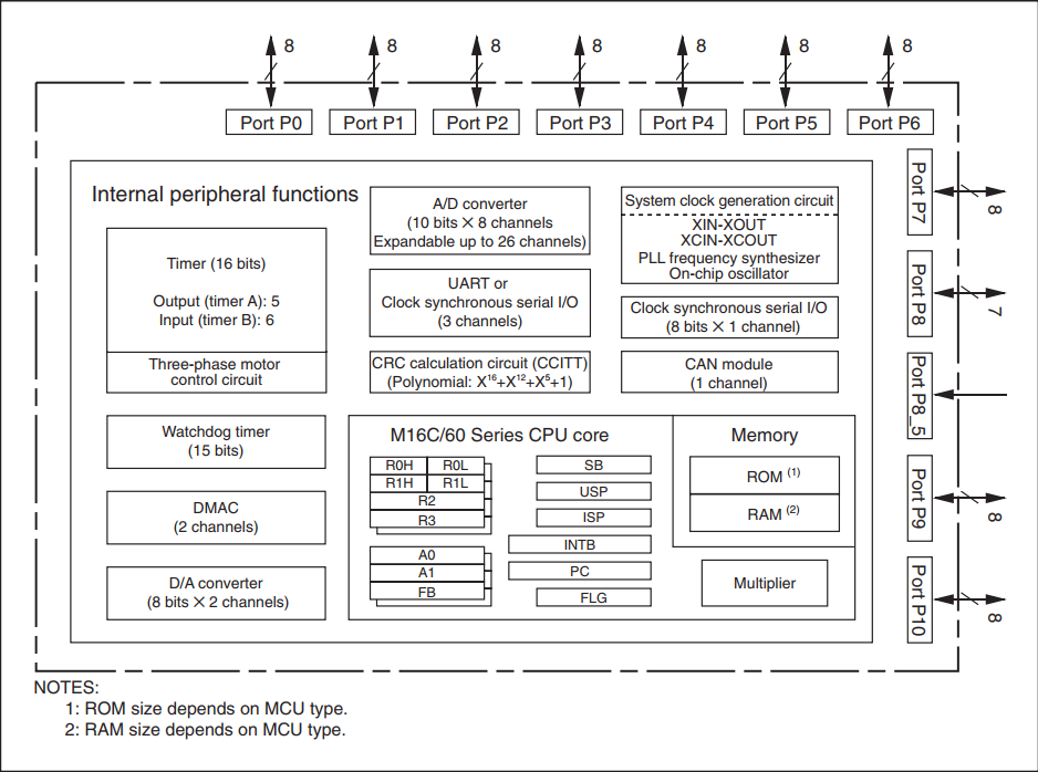
The pebble is a 16-bit microcontroller in a 100-pin QFP package. The kernel has 1 MB of address space, a clock frequency of 20 MHz for automotive performance. The set of peripherals is also very extensive: two 16-bit timers and the possibility of generating a 3-phase PWM for controlling motors, all sorts of UART, SPI, I2C naturally, 2 DMA channels, there is a built-in CAN2.0B controller, as well as a PLL. In my opinion it is very good for the old man. Here is an overview diagram from the documentation:
Since my task is to tear out the software, it is also very interested in memory. This MK was produced in two versions: masked and Flash. I got, as mentioned above, the M306N5FCTFP. About him, the description says the following:
- Flash memory version
- 128 KBytes + 4K (additional 4K - the so-called block A as a gift to the user for storing data, but can also store the program)
- V-ver. (automotive version with a range of + 125 ° C)
How to pull from the device what developers dragged
It is only natural that you should start trying to get something from the microcontroller by studying the mechanisms that are integrated by the chip developer for memory programming tasks. The manual states that the manufacturer kindly placed a bootloader in the memory for the needs of in-circuit programming of the device.
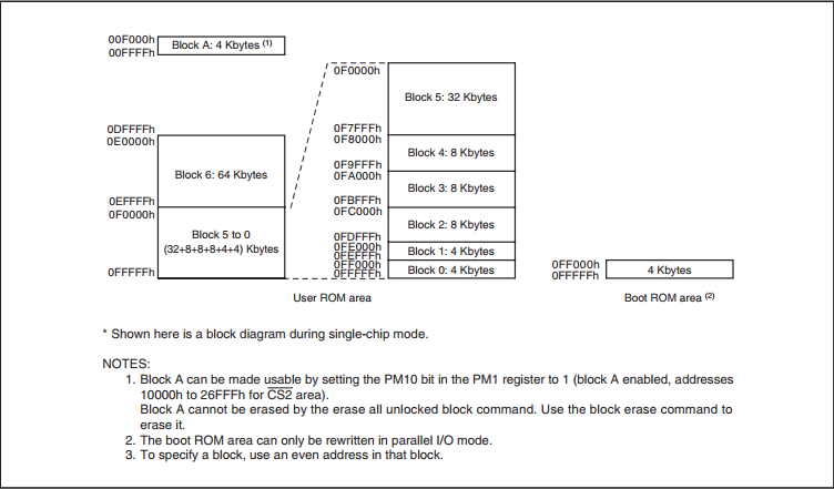
As can be seen from the picture above, the memory is divided into 2 parts: the user area, and the bootloader area. In the second, a default bootloader is loaded from the factory, which can write, read, erase user memory and communicates via an asynchronous, synchronous, or CAN interface. It is indicated that it can be rewritten to your own, or it may not be rewritten. In the end, this is easily verified by trying to knock on the standard bootloader at least through UART ... Looking ahead: the heater manufacturer did not bother with its bootloader, so you can dig further in this direction. Immediately make a reservation that there is still a parallel programming method, but since I did not have a programmer for this, I did not consider this option.
Entering the bootloader operation mode is provided by a certain combination at the inputs CNVSS, P5_0, P5_5 during a hardware reset. Next, either write your own utility to copy the contents of the memory, or use the finished one. Renesas provides its own utility, called the “M16C Flash Starter,” but its read function has been trimmed. It does not save what it reads to disk, but compares it with a file from disk. Those. in fact, this is not reading, but verification. However, there is a German free utility called M16C-Flasher, which can read firmware. In general, the initial toolkit was picked up.
About read protection
Everything would be quite simple if the bootloader did not provide protection against unauthorized access. I will just give a very free translation from the manual.
ID Verification Function
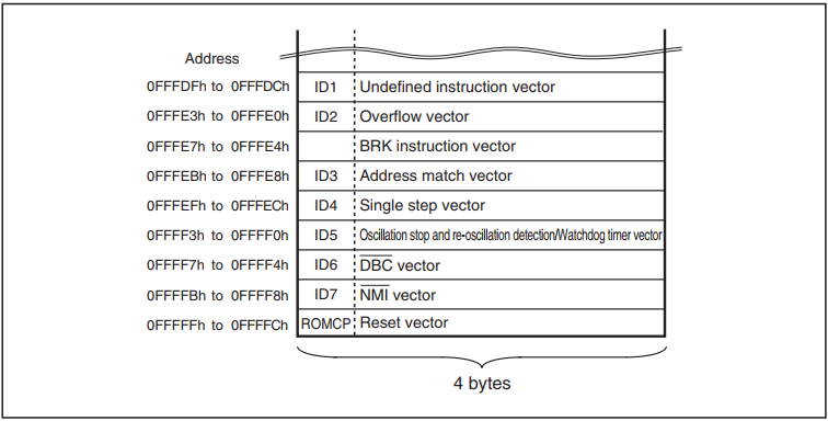
Used in serial and CAN exchange modes. The identifier transmitted by the programmer is compared with the identifier recorded in flash memory. If the identifiers do not match, commands sent by the programmer are not accepted. However, if 4 bytes of the reset vector are FFFFFFFFh, the identifiers are not compared, allowing all instructions to be executed. The identifier is 7 bytes stored sequentially, starting from the first byte, at addresses 0FFFDFh, 0FFFE3h, 0FFFEBh, 0FFFEFh, 0FFFF3h, 0FFFF7h, and 0FFFFBh.
Thus, in order to access the program, you need to know the cherished 7 bytes. Again, looking ahead, I connected to MK using the same “M16C Flash Starter” and made sure that combinations of zeros and FF did not work, and this issue would have to be solved somehow. Here, an idea immediately surfaced with an attack on third-party channels. Already I began to pretend to be a headscarf in my head, which allows me to measure the current in the power circuit, but decided that the Internet is large and most bikes have already been invented. Having driven a few searches, I quickly found on hackaday.io the Serge 'q3k' Bazanski project, titled "Reverse engineering Toshiba R100 BIOS." And within the framework of this project, the author solved essentially the exact same problem: extracting firmware from MK M306K9FCLR. Moreover - at that time the task was already successfully solved by him. On the one hand, I was a little upset - an interesting riddle was not solved by me. On the other hand, the task turned from a search for vulnerability, into its exploitation, which promised a much faster solution.
In a nutshell, q3k exactly the same logic began the study with an analysis of the current consumption, in this regard, it was in much more favorable conditions, because he had ChipWhisperer, I still haven’t got this thing. But since his first probe to remove the consumption current turned out to be inappropriate and he could not isolate something useful from the noise, he decided to try a simple attack on the response time. The fact is that the bootloader pulls the BUSY output during the execution of the command to inform the host that it is busy or is ready to execute the next command. According to q3k's assumption, measuring the time from transmitting the last bit of the identifier to removing the busy flag could serve as a source of information during enumeration. When checking this assumption by enumerating the first byte of the key, a time deviation was really found in only one case - when the first byte was equal to FFh. For the convenience of measuring time, the author even slowed down the MK by turning off the quartz resonator and applying a 666 kHz square wave to the clock input to simplify the measurement procedure. After that, the identifier was successfully selected and the software was retrieved.
The first pancake - a rake
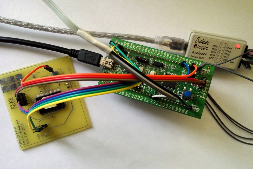
Ha! I thought ... Now I quickly rivet the program to my STM32VLDiscovery c STM32F100 on board, which will send the code and measure the response time, and spit out the measurement results in the terminal. Because Before that, the breadboard with the target controller was connected to the PC via the USB-UART adapter, so as not to change anything on the breadboard, we will work in asynchronous mode.
When at bootloader start the input CLK1 is pulled to the ground, he realizes that they want asynchronous communication from him. That's why I used it - the suspender was already soldered and I just connected the two boards with wires: Discovery and the breadboard with the target M306.
Note on the harmonization of levels:
Because Since M16 has TTL levels on the terminals, and STM32 has LVTTL (simplified, see the datasheet for details), then level matching is necessary. Because this is not a device that, like a well-known battery, should work, work and work, but in fact it connects once on the table, I didn’t bother with level translators: the five-volt MK digested output levels from STM32, in the sense of 3 volts it perceives as “1” , the outputs from M16 are fed to the 5V tolerant STM32 inputs so that it doesn’t feel bad, and we don’t forget to put the leg that pulls RESET M16 into open-drain output mode. I've forgotten, and this is + 2 hours to the piggy bank of lost time.
This minimum is enough to understand each other's glands.
The logic of the attacking software is as follows:
- We establish a connection with the controller. To do this, wait until the reset is completed, then transmit 16 zero characters with an interval of more than 20 ms. This is in order to work out the algorithm for automatically determining the exchange rate, because the interface is asynchronous, and MK knows nothing about its frequency. The starting speed of the transmitter should be 9600 baud, it is at this speed that the loader calculates. After that, if you wish, you can request another exchange rate out of five available in the range 9600-115200 (although in my case the loader refused to work on 115200). I do not need to change the speed, so I just requested the bootloader version to control the synchronization. We pass FBh, the loader responds with a line like "VER.1.01".
- We send the “unlock” command, which contains the current iteration of the key, and measure the time until the busy flag is cleared.

The command consists of F5h code, three bytes of the address where the identifier area begins (in my case, for the M16C kernel, it is 0FFFDFh), length (07h), and the identifier itself.
- We measure the time between the transmission of the last bit of the identifier and the removal of the busy flag.
- We increase the key byte being sorted (KEY1 at the initial stage), we return to step 2 until we sort through all 255 values of the current byte.
- We reset the statistics to the terminal (well, or we perform the analysis “on board”).
To communicate with the target MK, I used USART in STM32, for measuring time - a timer in Input Capture mode. The only thing, for simplicity, I measured the time not between the last bit of the key and the removal of the flag, but between the start of transmission and the flag. The reason was that the last bit could change, and in asynchronous mode there was nothing to attach to the capture input. At the same time, UART is hardware and the transmission time is basically identical and there should not be any tangible errors.
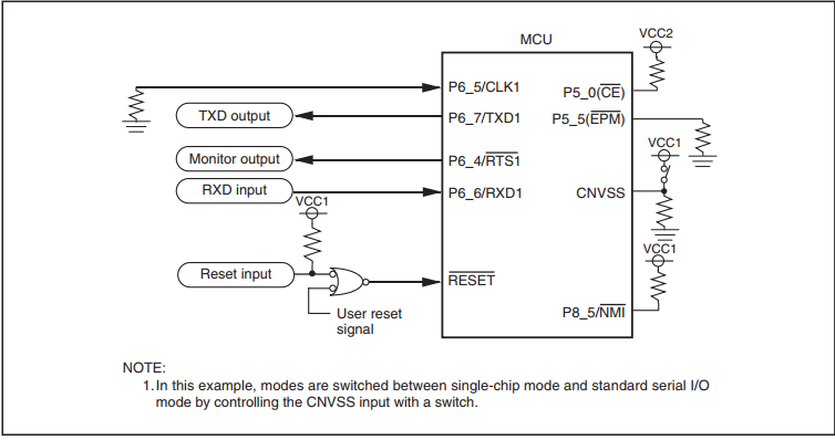
As a result, for all values, the results were identical. Completely identical. The clock frequency of the timer was 24 MHz, respectively, the time resolution is 41.6 ns. Well, ok, I tried to slow down the target MK. Nothing has changed. Here the question was born in my head: what am I doing wrong, as q3k did? After comparison, the difference was found: it uses a synchronous exchange interface (SPI), and I am asynchronous (UART). And somewhere here, I drew attention to the moment that I missed at the beginning. Even on wiring diagrams for synchronous and asynchronous bootloader modes, the ready output is named differently:
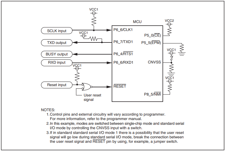
In synchronous it is "BUSY", in asynchronous it is "Monitor". We look at the table “Output Functions in Standart Serial I / O Mode”:

"Semyon Semenych ..."
Missed at first a trifle led the wrong way. Actually, if in synchronous mode this is exactly the bootloader busy flag, then in asynchronous mode (the one that serial I / O mode 2) is just a “blinker” to indicate operation. Perhaps, in general, the hardware signal of readiness of the transceiver, and therefore the amazing accuracy of its raising.
In general, we solder the resistor on the SCLK pin from the ground to VCC, solder the wire there, hook it all to SPI and start over ...
Success!
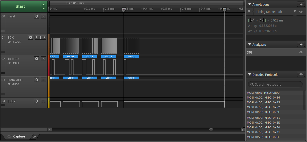
In synchronous mode, everything is almost the same, only no preliminary procedure for establishing a connection is required, synchronization is simplified, and time capture can be performed more accurately. If I immediately chose this mode I would save time ... I again did not complicate and measure the time from the last bit, but started the timer before starting the transfer of the last byte of the key, i.e. we turn on the timer and send it to the KEY7 transmitter (in the screenshot above, from the logic analyzer, you can see the distance between the cursors. This is the measured time interval).
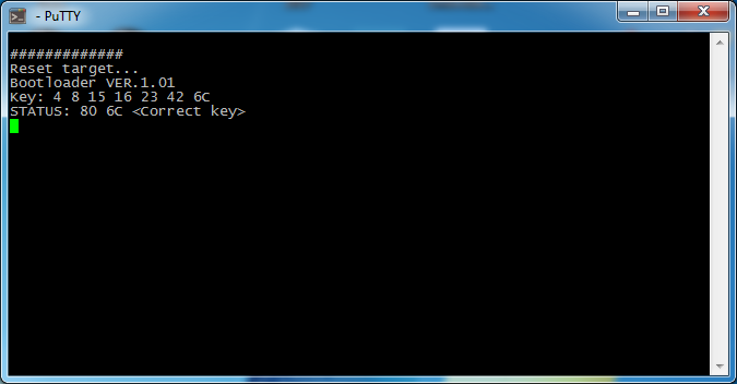
This was more than enough for a successful identification. Here is the enumeration of one byte:

On the x-axis we have the number of discrete counts, on the y-axis, respectively, the transmitted key value. The signal-to-noise ratio is such that even no filters are required, just like at school in an informatics lesson: we find the maximum in the array and go to the selection of the next byte. The first 6 bytes are selected easily and quickly, a little more difficult with the last: there it’s just arrogant enumeration that doesn’t work, you need to reset the “victim” before each attempt. As a result, it takes about 400 ms for each attempt, and the search is in the worst case, in the region of one and a half minutes. But this is the worst. After each attempt, we request a status and, as soon as we guess, stop. At first, in general, I just simply quickly went over the identifier with pens, inserting the console output into excel and plotting the graph, all the more so as it was a one-time task, but for the article I decided to add automatic iteration, for the sake of a beautiful console ...
Of course, if the developer erased the bootloader (replaced by his own), it would not be so easy to get out, but in automotive electronics, often MKs are not closed at all. In particular, in the control unit from another heater, in which the V850 of the same Renesas was installed, everything was decided by soldering a pair of wires and copying the firmware with a standard utility. This is the whole cryptocurrency engine in the ECU world. Apparently the manufacturers do not like the phenomenon of chip tuning and other types of interference ... Although this is like a race of armor and shells - the glands are steeper, more expensive, but there is no winner ...
References:
All Articles