SamsPcbGuide, part 11: Technology - BGA-type enclosures, plastic and space
In discussions to a previous article, proton17 wrote that regular BGAs do not fly into space, giving links to CCGA-type enclosures as an example of reliability. I decided to sort this issue out and found a lot of interesting information (thanks in large part to this ↓ person).
Despite its advantages (the maximum number of conclusions with respect to dimensions at a given step, low terminal inductance, self-leveling when soldering), BGA-type cases have a serious drawback for reliable applications - the impossibility of reliable visual quality control of soldered joints.
The question of the applicability of BGA components in reliable applications is not a new one; back in 1995, JPL conducted research on their reliability under various conditions. The results of the work were consistently presented in numerous publications by the real guru of this topic, R. Jafarian [1-5]. At first, ceramic and “ordinary” plastic cases were examined for flatness of the surface using laser scanning. For the measure of flatness, the difference between the lowest and the highest ball was chosen. The smaller this difference, the less the likelihood of defects when soldering. Ceramic bodies had more flatness, it also improved with a decrease in the number of conclusions. This parameter is all the more critical the more high-temperature solder is used for soldering. The second stage - mounting on printed circuit boards (FR-4 and polyimide) and thermal cycling. The electrical connections on the board and inside the test BGA package were organized in such a way as to form several groups of serial connections (English daisy chain). In each of these groups, the presence of connection failure was monitored by the criterion for excess resistance of 1 kOhm by more than 1 μs. This criterion is defined in IPC-SM-785, however, it is not sufficient, since even a completely cracked connection may not go beyond the specified threshold value due to contact pinching due to adjacent terminals [4].
Due to the large difference between the KTP of the ceramic and the FR-4 / polyimide, the CBGA casing failed earlier than the plastic ones. Also, earlier failures showed plastic cases with a full array of leads, in contrast to cases with peripheral filling, since under the crystal there is a local increase in the KTP mismatch between the case and the board and it was there that the first failures occurred in the connections.
Among the results, the influence of the glass transition temperature of the material of the printed circuit board on the reliability for an extended temperature range is noted. FR-4 showed on average weaker results than polyamide. This result is also confirmed in the article [6]: the use of the FR-5 printed circuit board (with Tg ~ 170 o C and KTP ~ 13 − 10 −6 K −1 ) provides a four-fold increase in reliability compared to the usual FR-4 for the SON- case type.
It is worth noting that the KTP of a printed circuit board can differ even within the board and depends on its topology. A wide range of values from 12 to 24 ∙ 10 −6 K −1 is given in [6]. There is also interesting data (Table 1) on the dependence of PBGA reliability on the diameter of the ball, contact pads (KP) on the board (NSMD type) and the base of the chip (SMD type). Their analysis reveals the following patterns:

The article [7] experimentally shows an increase in the number of thermal cycles with a decrease in the thickness of the ceramic base of the body. I could not get acquainted with the previous article of one of the authors with a description of the process model, but the general considerations are as follows: the thinner the body, the less it resists tensile strength, the less load on the conclusions.
The rate of temperature change affects the predominant place of occurrence of defects in the joints - with fast (when local stresses arise) it is from the side of the case, with slow (when the system manages to come into thermal equilibrium) - from the side of the printed circuit board. For an extended temperature range, the largest number of failures of CBGA ceramic cases was in the connection of the case (63Sn37Pb) and the ball (90Pb10Sn).
So, the main obvious patterns, experimentally confirmed back in 1995, for the reliability of BGA components are determined by thermal expansion and are as follows:
Why use ceramic cases? This issue was addressed by BarsMonster in one of the articles . About the fact that in plastic the jumpers are supported along the entire length by the compound, on the one hand, it is logical, but on the other hand, the KTP mismatch of the materials of the plastic case (compound, silicon, textolite, metal jumper) creates a large number of problems in an extended temperature range. Additional arguments in favor of the use of ceramic cases are the KTE value close to silicon, high thermal conductivity, a wide temperature range (which is important for the assembly process), higher hydrophobicity, and easier sealing process development.
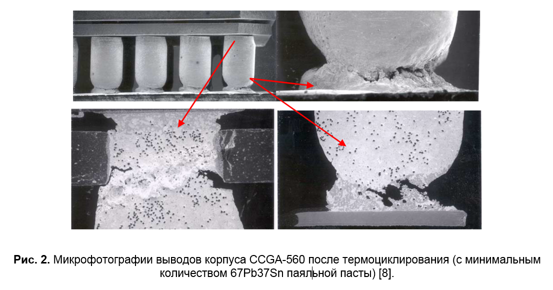
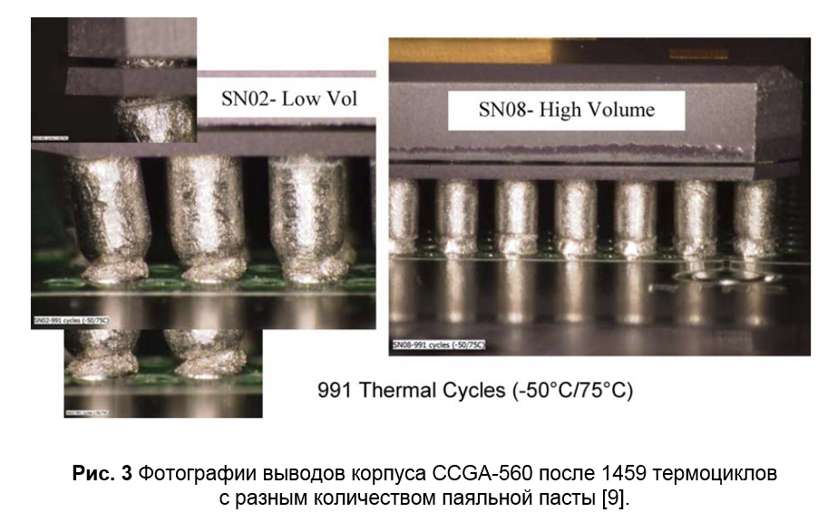
On Spirit and Opportunity, ceramic bodies were used, but not the CBGA type, but the CCGA type (Fig. 1): in them the balls were replaced by columns (sometimes reinforced with a copper spiral) that can withstand heavy loads ( here is the data that a 2-fold increase in height reduces mechanical stress and strain by 30%). Despite the fact that these missions have successfully completed and even exceeded their tasks, it is worth noting that the productive processors in the CCGA-housings were in a temperature-controlled unit. In [8, 9], a comparison of CCGA and its corresponding PBGA under various conditions is presented. After 1075 thermal cycles –50 / 75 ° C, the CCGA-560 experienced the first destruction of the contact on the side of the case (an increased amount of solder paste was used for installation, which improved the reliability of the connection on the side of the board, see Fig. 2 and 3), while in the PBGA-560 for 2000 cycles of failures were not detected.

It is interesting to think about why the extreme pins are biased towards the center on the side of the board. The KTP of the printed circuit board is larger than the KTP of the ceramic, and then this means that the destruction occurs on compression, in the region of negative temperatures. This led me to the following reasoning: soldering and fixing the relative position occurs near the melting temperature of the solder paste, i.e. ~ 183 o C for 63Sn37Pb, so the entire range of operating temperatures is in the compression region of the printed circuit board relative to the ceramic base of the case. And then the temperature of the neutral point is not 25 o C, this is the melting point of the solder paste.
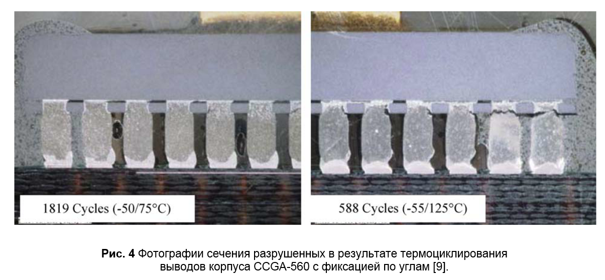
In order to reduce the load on the terminals of the BGA-cases (including as a result of mechanical factors), several methods are used: fixation on the corners (English corner-staking), compounding the space between the case and the board (English underfill). However, the test results in [9] show that such a technology not only does not solve the problem, but can, on the contrary, only worsen the structural stability to the effects of temperature changes (Fig. 4).
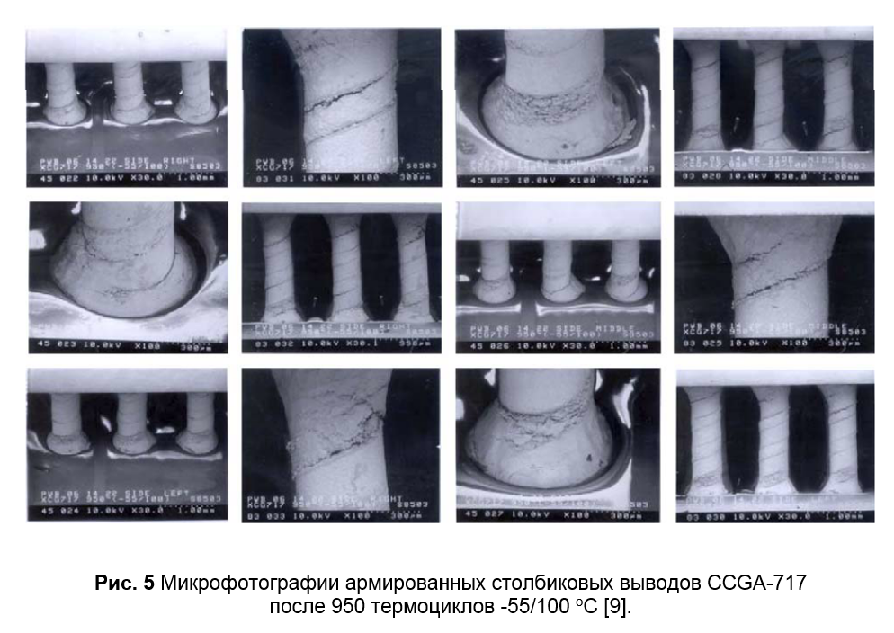
The CCGA-717 case with reinforced columns of smaller diameter was also tested [9]. Compared with CCGA-560 with unreinforced leads, it showed greater resistance to thermal cycling: after 950 cycles of -55/100 o C there were no electrical failures, but defects on the leads had already begun to form (Fig. 5). In the public domain there are also the results of successful tests of the CCGA-472 from the Aeroflex laboratory according to NASA standards.
The article [5] presents the results of a study of the effect of the finish coating of a printed circuit board on the reliability of BGA components. It was noted that for ENIG, in contrast to HASL and OSP, which were characterized by viscous destruction of the findings, some findings showed brittle destruction of the findings. The IPC-9701A standard, which describes the methodology for testing the reliability of soldered joints, prohibits the use of other PCB coatings, except HASL, OSP and IAg, in order to avoid the effects of intermetallic compounds (also, by the way, the standard recommends the use of NSMD-type contact pads with indented masks). In the framework of special studies [10, 11], the problems of using ENIG as a topcoat failed to detect any patterns and, thus, a decrease in the reliability of the connection is a difficult to predict event. Apparently, for this reason, the standard does not recommend the use of such a finish. By the way, as an alternative coating, among others, ENEPIG coating was considered, which showed good results ( in the original - “performed very well and requires more testing”).
Table 2 summarizes the data from experiments on the reliability of BGA-type components, the analysis of which indicates the presence of some regularities (for example, a decrease in the thickness of the ceramic base significantly reduces the load on the conclusions). This data can only serve as a guideline in the design, the reliability criterion is an experiment for a specific design and assembly technology. At the end of the article [9], valuable recommendations are given on the use of BGA components based on a summary of NASA's experience from a person who has been working on the reliability of BGA components since 1995. Here are some points:
There is other data : in one of the JAXA presentations, it is said that its use for CBGA packages increases the number of cycles before a failure occurs on average 1.7 times. Most often, underfill-type compounds are used in CSP-type cases, where the main task, in dimensions as close as possible to the size of the crystal, is to ensure a transition between low KTP of silicon and KTP of a printed circuit board. For BGA components, as already mentioned, it is necessary to conduct tests in each specific case (without the possibility of transferring the results even when one of the parameters, including the technological one) changes in accordance with the model of external influencing factors.
How many thermal cycles must the body withstand? Of course, this depends on the model of influencing factors. With the optimized assembly technology, the generalized reliability criterion in the absence of failures for 500 cycles of -60/125 is satisfied by many types of cases (see table 2). However, “not a single thermal cycling”, the case must not accumulate moisture, it must provide low thermal resistance, it must provide resistance to mechanical factors, etc. And according to the full list of criteria for ceramic cases, reliability is statistically higher. Manufacturers of electronic components for space equipment, such as Aeroflex and MSK, release their microcircuits in ceramic and metal-glass cases. Yes, for the execution of the BGA type, installation on PCBs creates problems due to the KTR mismatch, therefore, it is necessary to invent ways to increase the reliability of the connections - reducing the thickness of the base, the use of column leads, compounding, etc.
The request to reduce the mass of spacecraft (first of all, the development of small spacecraft) is pushing manufacturers to produce reliable electronic components in plastic cases, there are already solutions on the market (in addition, they are also declared as budget ones). Perhaps in the near future the amount of reliable, space-certified plastic will grow, meeting the needs of low-Earth orbit missions, and ceramic cases will be transferred to LTCC printed circuit boards in order to plow deep space.
[1] Reza Ghaffarian, “BGAs for High Reliability Applications”, 1998.
[2] Reza Ghaffarian, “Ball Grid Array Reliability Assessment for Aerospace Applications”, 1997
[3] Reza Ghaffarian, “Reliability and Failure Analyses of Thermally Cycled Ball Grid Array Assemblies”, 1998
[4] Reza Ghaffarian, “Reliability of BGA Packages for Highly Reliable Applications and Chip Scale Package Board Level Reliability”, 1997
[5] Reza Ghaffarian, “Assembly Reliability Of BGAs And Effects Of Boards Finish”, 1998
[6] Jean-Paul Clech, ”Solder Joint Reliability Of CSP Versus BGA Assemblies”, 2000
[7] Raj N. Master, Gregory B. Martin, etc. “Ceramic Ball Grid Array for AMD K6 Microprocessors Applications”, 1998
[8] Reza Ghaffarian, “Effect of Area Array Package Types on Assembly Reliability And Comments on IPC-9701A”, 2005
[9] Reza Ghaffarian, “CCGA packages for space applications", 2006
[10] FDBruce Houghton. “ITRI Project on Electroless Nickel / Immersion Gold Joint Cracking”, 2000
[11] FDBruce Houghton. “Solving the ENIG Black Pad Problem: An ITRI Report on Round 2”, 1999
Despite its advantages (the maximum number of conclusions with respect to dimensions at a given step, low terminal inductance, self-leveling when soldering), BGA-type cases have a serious drawback for reliable applications - the impossibility of reliable visual quality control of soldered joints.
The question of the applicability of BGA components in reliable applications is not a new one; back in 1995, JPL conducted research on their reliability under various conditions. The results of the work were consistently presented in numerous publications by the real guru of this topic, R. Jafarian [1-5]. At first, ceramic and “ordinary” plastic cases were examined for flatness of the surface using laser scanning. For the measure of flatness, the difference between the lowest and the highest ball was chosen. The smaller this difference, the less the likelihood of defects when soldering. Ceramic bodies had more flatness, it also improved with a decrease in the number of conclusions. This parameter is all the more critical the more high-temperature solder is used for soldering. The second stage - mounting on printed circuit boards (FR-4 and polyimide) and thermal cycling. The electrical connections on the board and inside the test BGA package were organized in such a way as to form several groups of serial connections (English daisy chain). In each of these groups, the presence of connection failure was monitored by the criterion for excess resistance of 1 kOhm by more than 1 μs. This criterion is defined in IPC-SM-785, however, it is not sufficient, since even a completely cracked connection may not go beyond the specified threshold value due to contact pinching due to adjacent terminals [4].
Due to the large difference between the KTP of the ceramic and the FR-4 / polyimide, the CBGA casing failed earlier than the plastic ones. Also, earlier failures showed plastic cases with a full array of leads, in contrast to cases with peripheral filling, since under the crystal there is a local increase in the KTP mismatch between the case and the board and it was there that the first failures occurred in the connections.
Among the results, the influence of the glass transition temperature of the material of the printed circuit board on the reliability for an extended temperature range is noted. FR-4 showed on average weaker results than polyamide. This result is also confirmed in the article [6]: the use of the FR-5 printed circuit board (with Tg ~ 170 o C and KTP ~ 13 − 10 −6 K −1 ) provides a four-fold increase in reliability compared to the usual FR-4 for the SON- case type.
It is worth noting that the KTP of a printed circuit board can differ even within the board and depends on its topology. A wide range of values from 12 to 24 ∙ 10 −6 K −1 is given in [6]. There is also interesting data (Table 1) on the dependence of PBGA reliability on the diameter of the ball, contact pads (KP) on the board (NSMD type) and the base of the chip (SMD type). Their analysis reveals the following patterns:
- The increase in the diameter of the ball, ceteris paribus, increased the number of thermal cycles withstand by ~ 20-30%.
- Increasing the diameter of the gearbox only on the side of the printed circuit board reduces reliability, since the height of the ball decreases. However, with a simultaneous increase in the diameter of the site based on PBGA, the reliability losses associated with a decrease in height are compensated by an improvement in the communication area, and the overall effect becomes positive.
- Maximum reliability was obtained when the diameter of the gearbox on the board was slightly less than on the basis of the microcircuit. The author refers to a similar result obtained in another work. Unfortunately, there is no comparison for the case with a large ball diameter.
The article [7] experimentally shows an increase in the number of thermal cycles with a decrease in the thickness of the ceramic base of the body. I could not get acquainted with the previous article of one of the authors with a description of the process model, but the general considerations are as follows: the thinner the body, the less it resists tensile strength, the less load on the conclusions.
The rate of temperature change affects the predominant place of occurrence of defects in the joints - with fast (when local stresses arise) it is from the side of the case, with slow (when the system manages to come into thermal equilibrium) - from the side of the printed circuit board. For an extended temperature range, the largest number of failures of CBGA ceramic cases was in the connection of the case (63Sn37Pb) and the ball (90Pb10Sn).
So, the main obvious patterns, experimentally confirmed back in 1995, for the reliability of BGA components are determined by thermal expansion and are as follows:
- The larger the housing and the number of leads, the lower the reliability.
- Conclusions that are farthest from the center are most vulnerable to destruction. For plastic BGA-cases, in addition, the conclusions in the area of the crystal are vulnerable
- Ceramic cases on a PCB board show low reliability. In addition, they are not so well aligned when soldering (since they have a larger mass) and are more sensitive to the quantity and quality of applying solder paste, which complicates the formulation process of reliable installation of components.
Lyrical digression. The use of printed circuit boards based on LTCC ceramics would remove the problem of KTP mismatch. Perhaps this is one of the directions for the development of REA for space, which will lead to a decrease in the cost of such printed circuit boards.
Why use ceramic cases? This issue was addressed by BarsMonster in one of the articles . About the fact that in plastic the jumpers are supported along the entire length by the compound, on the one hand, it is logical, but on the other hand, the KTP mismatch of the materials of the plastic case (compound, silicon, textolite, metal jumper) creates a large number of problems in an extended temperature range. Additional arguments in favor of the use of ceramic cases are the KTE value close to silicon, high thermal conductivity, a wide temperature range (which is important for the assembly process), higher hydrophobicity, and easier sealing process development.
On Spirit and Opportunity, ceramic bodies were used, but not the CBGA type, but the CCGA type (Fig. 1): in them the balls were replaced by columns (sometimes reinforced with a copper spiral) that can withstand heavy loads ( here is the data that a 2-fold increase in height reduces mechanical stress and strain by 30%). Despite the fact that these missions have successfully completed and even exceeded their tasks, it is worth noting that the productive processors in the CCGA-housings were in a temperature-controlled unit. In [8, 9], a comparison of CCGA and its corresponding PBGA under various conditions is presented. After 1075 thermal cycles –50 / 75 ° C, the CCGA-560 experienced the first destruction of the contact on the side of the case (an increased amount of solder paste was used for installation, which improved the reliability of the connection on the side of the board, see Fig. 2 and 3), while in the PBGA-560 for 2000 cycles of failures were not detected.
It is interesting to think about why the extreme pins are biased towards the center on the side of the board. The KTP of the printed circuit board is larger than the KTP of the ceramic, and then this means that the destruction occurs on compression, in the region of negative temperatures. This led me to the following reasoning: soldering and fixing the relative position occurs near the melting temperature of the solder paste, i.e. ~ 183 o C for 63Sn37Pb, so the entire range of operating temperatures is in the compression region of the printed circuit board relative to the ceramic base of the case. And then the temperature of the neutral point is not 25 o C, this is the melting point of the solder paste.
In order to reduce the load on the terminals of the BGA-cases (including as a result of mechanical factors), several methods are used: fixation on the corners (English corner-staking), compounding the space between the case and the board (English underfill). However, the test results in [9] show that such a technology not only does not solve the problem, but can, on the contrary, only worsen the structural stability to the effects of temperature changes (Fig. 4).
The CCGA-717 case with reinforced columns of smaller diameter was also tested [9]. Compared with CCGA-560 with unreinforced leads, it showed greater resistance to thermal cycling: after 950 cycles of -55/100 o C there were no electrical failures, but defects on the leads had already begun to form (Fig. 5). In the public domain there are also the results of successful tests of the CCGA-472 from the Aeroflex laboratory according to NASA standards.
The article [5] presents the results of a study of the effect of the finish coating of a printed circuit board on the reliability of BGA components. It was noted that for ENIG, in contrast to HASL and OSP, which were characterized by viscous destruction of the findings, some findings showed brittle destruction of the findings. The IPC-9701A standard, which describes the methodology for testing the reliability of soldered joints, prohibits the use of other PCB coatings, except HASL, OSP and IAg, in order to avoid the effects of intermetallic compounds (also, by the way, the standard recommends the use of NSMD-type contact pads with indented masks). In the framework of special studies [10, 11], the problems of using ENIG as a topcoat failed to detect any patterns and, thus, a decrease in the reliability of the connection is a difficult to predict event. Apparently, for this reason, the standard does not recommend the use of such a finish. By the way, as an alternative coating, among others, ENEPIG coating was considered, which showed good results ( in the original - “performed very well and requires more testing”).
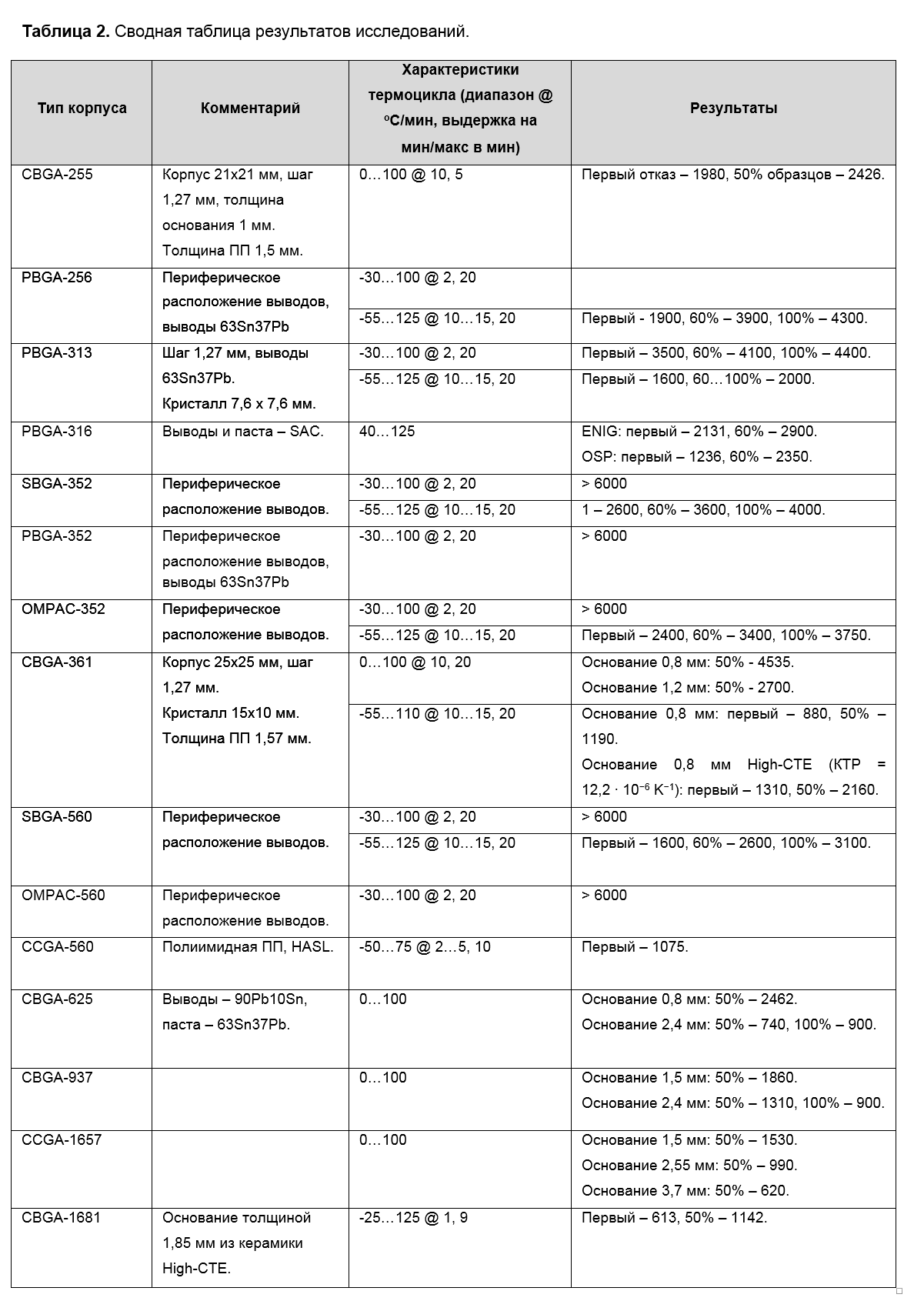
Table 2 summarizes the data from experiments on the reliability of BGA-type components, the analysis of which indicates the presence of some regularities (for example, a decrease in the thickness of the ceramic base significantly reduces the load on the conclusions). This data can only serve as a guideline in the design, the reliability criterion is an experiment for a specific design and assembly technology. At the end of the article [9], valuable recommendations are given on the use of BGA components based on a summary of NASA's experience from a person who has been working on the reliability of BGA components since 1995. Here are some points:
- Most PBGA cases provide sufficient reliability for missions with limited temperature differences (for example, controlled temperature in the module case). With a long mission, corps with a large number of conclusions (more than 500) must be tested.
- Ceramic BGA cases with a small number of leads (less than 400) can meet the reliability requirements for short-term missions with limited temperature differences, but for long-term missions, qualification tests must be passed even in case of lowered requirements for temperature differences. For cases with a large number of conclusions (more than 500), tests are required in all cases.
- The use of an “underfill” compound is not recommended for CCGAs due to the high clearance between the case and the printed circuit board. In case of use, the KTP of the compound should be close to the KTP of the printed circuit board (load in the plane) and conclusions (load in the direction of the Z axis), in addition, individual tests for each application are necessary.
- If it is necessary to increase resistance to mechanical stresses, corner fixing (English corner staking, edge bonding) is more preferable for CCGA and CBGA cases in comparison with underfill technology. However, even here you can degrade the reliability of improperly selected materials.
There is other data : in one of the JAXA presentations, it is said that its use for CBGA packages increases the number of cycles before a failure occurs on average 1.7 times. Most often, underfill-type compounds are used in CSP-type cases, where the main task, in dimensions as close as possible to the size of the crystal, is to ensure a transition between low KTP of silicon and KTP of a printed circuit board. For BGA components, as already mentioned, it is necessary to conduct tests in each specific case (without the possibility of transferring the results even when one of the parameters, including the technological one) changes in accordance with the model of external influencing factors.
How many thermal cycles must the body withstand? Of course, this depends on the model of influencing factors. With the optimized assembly technology, the generalized reliability criterion in the absence of failures for 500 cycles of -60/125 is satisfied by many types of cases (see table 2). However, “not a single thermal cycling”, the case must not accumulate moisture, it must provide low thermal resistance, it must provide resistance to mechanical factors, etc. And according to the full list of criteria for ceramic cases, reliability is statistically higher. Manufacturers of electronic components for space equipment, such as Aeroflex and MSK, release their microcircuits in ceramic and metal-glass cases. Yes, for the execution of the BGA type, installation on PCBs creates problems due to the KTR mismatch, therefore, it is necessary to invent ways to increase the reliability of the connections - reducing the thickness of the base, the use of column leads, compounding, etc.
It is important to understand that it is not a matter of packaging technology in general, but whether a particular microcircuit meets the requirements of reliability and resistance to influencing factors. You can use a commercial microcircuit in a plastic case, if it passes the full test cycle. At the same time, successful tests will not mean that the “same” microcircuit from another manufacturer or even from another batch will satisfy the reliability requirements. This is the difference between a reliable ECB, which is inherent in the price - the manufacturer takes on the costs of the tests. The same 3D PLUS carries out the selection of microchips in plastic for some of its microassemblies, but such products are already much more expensive. Another way is to perform testing and selection on the consumer side. This can be justified if the required functionality is not implemented in reliable execution, or if the external impact model and reliability requirements for the target mission are significantly lower than the typical reliable electronic batteries on the market.
The request to reduce the mass of spacecraft (first of all, the development of small spacecraft) is pushing manufacturers to produce reliable electronic components in plastic cases, there are already solutions on the market (in addition, they are also declared as budget ones). Perhaps in the near future the amount of reliable, space-certified plastic will grow, meeting the needs of low-Earth orbit missions, and ceramic cases will be transferred to LTCC printed circuit boards in order to plow deep space.
Literature
[1] Reza Ghaffarian, “BGAs for High Reliability Applications”, 1998.
[2] Reza Ghaffarian, “Ball Grid Array Reliability Assessment for Aerospace Applications”, 1997
[3] Reza Ghaffarian, “Reliability and Failure Analyses of Thermally Cycled Ball Grid Array Assemblies”, 1998
[4] Reza Ghaffarian, “Reliability of BGA Packages for Highly Reliable Applications and Chip Scale Package Board Level Reliability”, 1997
[5] Reza Ghaffarian, “Assembly Reliability Of BGAs And Effects Of Boards Finish”, 1998
[6] Jean-Paul Clech, ”Solder Joint Reliability Of CSP Versus BGA Assemblies”, 2000
[7] Raj N. Master, Gregory B. Martin, etc. “Ceramic Ball Grid Array for AMD K6 Microprocessors Applications”, 1998
[8] Reza Ghaffarian, “Effect of Area Array Package Types on Assembly Reliability And Comments on IPC-9701A”, 2005
[9] Reza Ghaffarian, “CCGA packages for space applications", 2006
[10] FDBruce Houghton. “ITRI Project on Electroless Nickel / Immersion Gold Joint Cracking”, 2000
[11] FDBruce Houghton. “Solving the ENIG Black Pad Problem: An ITRI Report on Round 2”, 1999
All Articles