Do-it-yourself manicure vacuum cleaner
Good day to all! Today I will collect a manicure fan or, more precisely, it will be called a manicure vacuum cleaner.

Its main task is to draw in the nail crumb and dust, which is formed as a result of the work of the cutter.
This allows you to keep your desktop clean and not to breathe light dusty air. Similar fans can be found in any nail service. After browsing the Internet, I realized that the device is in demand and many are trying to make it themselves.
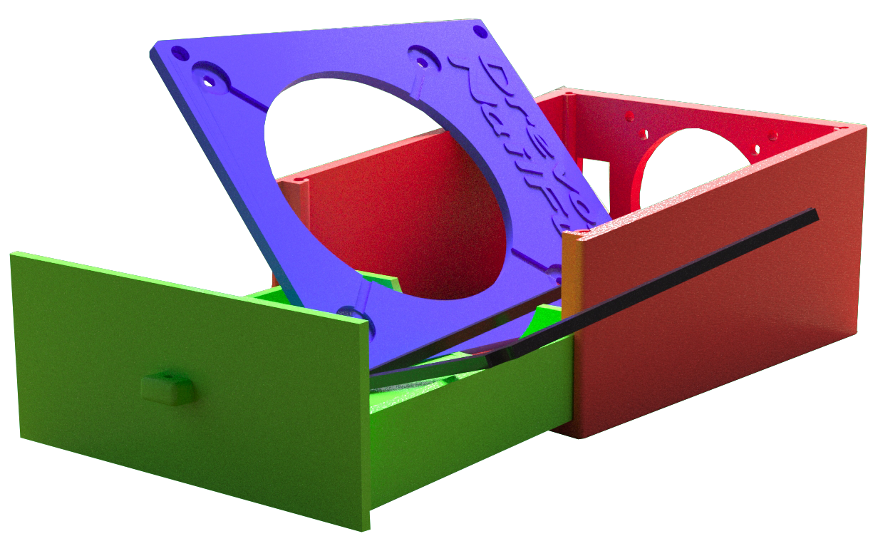
I developed a 3D model of the unit body.
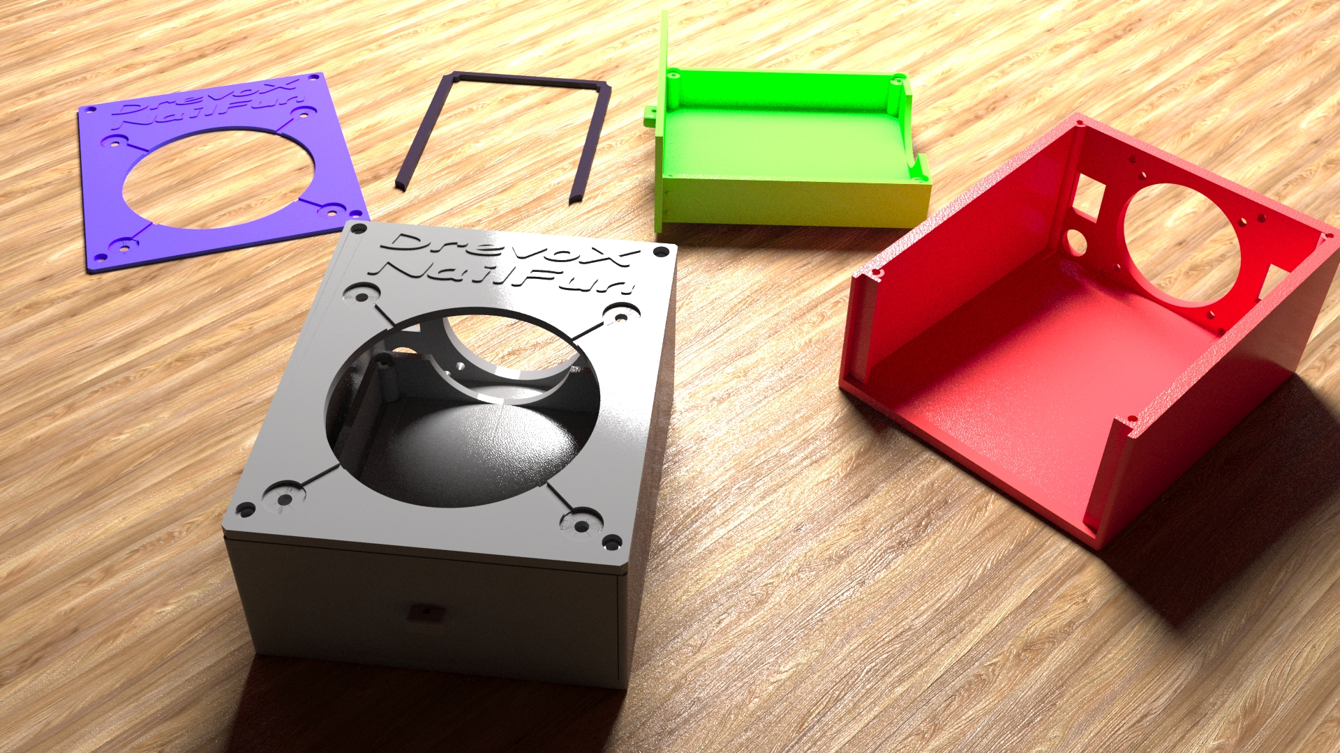
We will collect it! The housing consists of 3 parts, plus a retainer. The project turned out to be budgetary, it will be useful to many beginner manicure masters.
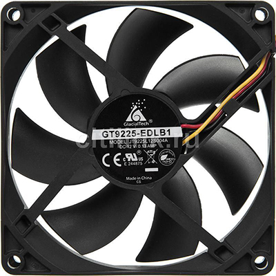
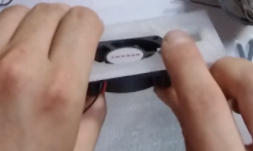
In addition to the model printed on a 3D printer, we will need: a large 12V fan of 92 by 92 mm in size, which will serve as a retractor fan and a small one, 50 by 50 or 60 by 60 in size, which will draw air from the case.
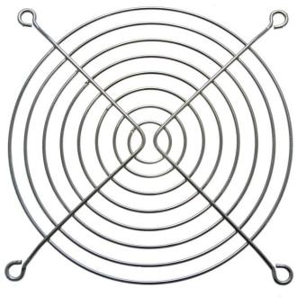
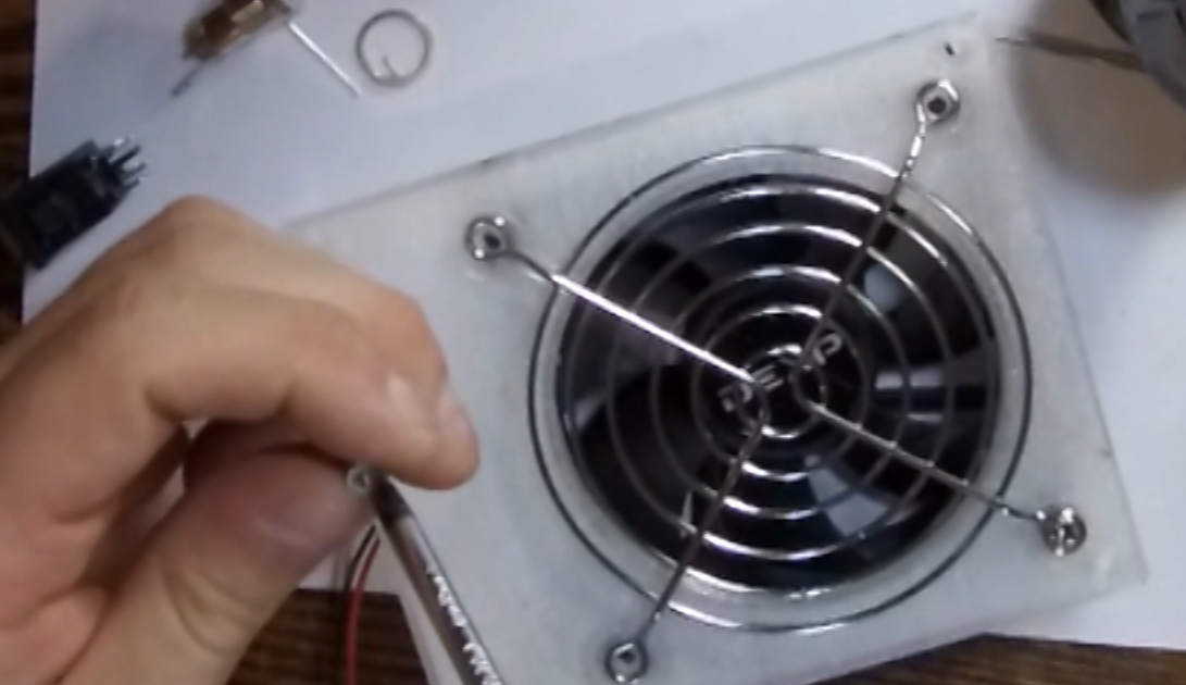
So that the dust does not fly out of the case, and the fingers do not fall into the blades, we will use protective grilles.
On a large fan - metal with large openings:
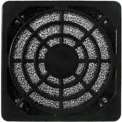
And the exhaust fan is small with a filter of fine dust.
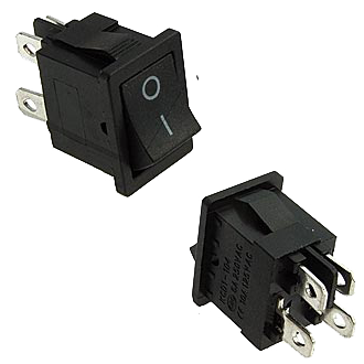
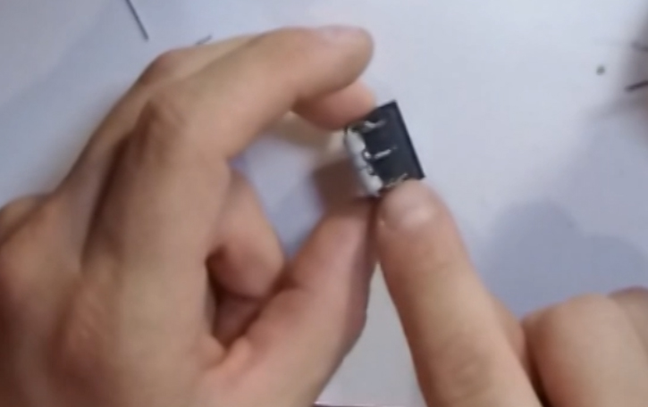
We also need one on / off button:
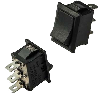
And a button to switch modes.
One resistance per 2 watts per 50 ohms.
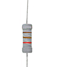
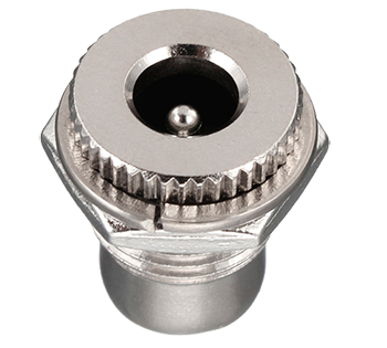
You can use any resistance in the range from 30 to 80 Ohms, which will allow us to lower the fan speed for the second mode. As power, we need a 12V 1 or 2 amp block and a power connector on the chassis for it.
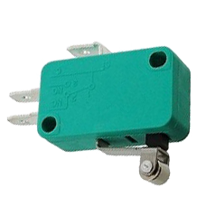
You will also need about 1 meter of wires for installation, preferably different colors and soldering accessories. It is enough to take wires of 0.5 or 0.75 section. The project can be supplemented with an end microswitch to turn off the fans when the dust compartment is opened:
... and backlight for greater effect)
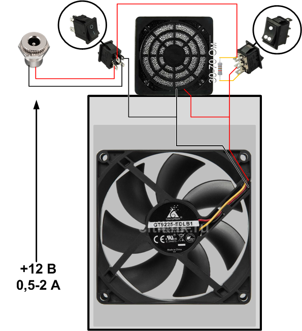
I provide simple schemes for our project:
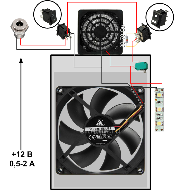
And an augmented project with limit switch and backlight:
The first thing we do is switch the mode button. At the extreme contacts, we will solder our resistance.
Such a connection will simplify the circuit and we can refuse the extra wire. The power supply is made to any of the resistance contacts on the one hand,
the power tap, which goes directly to the fans, is taken from the central contact of the mode switch key.
Next, we mount our small exhaust fan to the body, fasten it with two screws diagonally to the body.
On the reverse side we install a plastic grill with a filter. We fasten the grate with 4 screws to the box body.
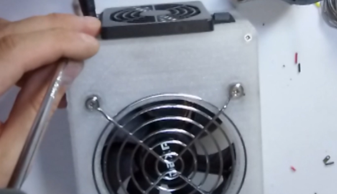
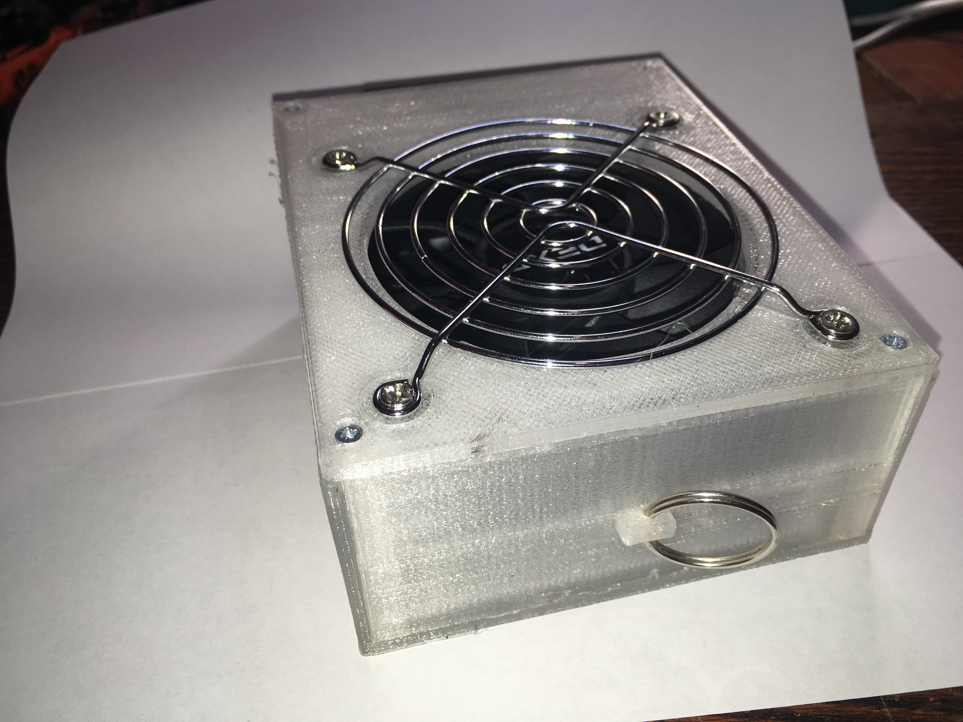
Now let's install a large exhaust fan. We will fasten it together with a metal grill 92 by 92 mm to the lid of our plastic box. We will fasten the screws that were included with the fan.
These are often used for mounting fans in computer cases. You can buy them, like the fans themselves, in any computer or radio store.
Be sure to observe the air flow direction of the fans! It is worth paying attention to the selection of a large exhaust fan. The more powerful it is, the better it will be to absorb trash and it will be more comfortable to work.
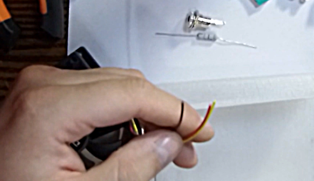
We check our dust collector so that it freely enters the case after installing the fans. Next, we need to strip the wires and connect the fans together.
If your fan has 3 wires, then we use only black and red. 3 wire just cut off, it is necessary to control the speed of the fan.
We will not complicate the project with circuits with infinitely variable speed control and will do much easier.
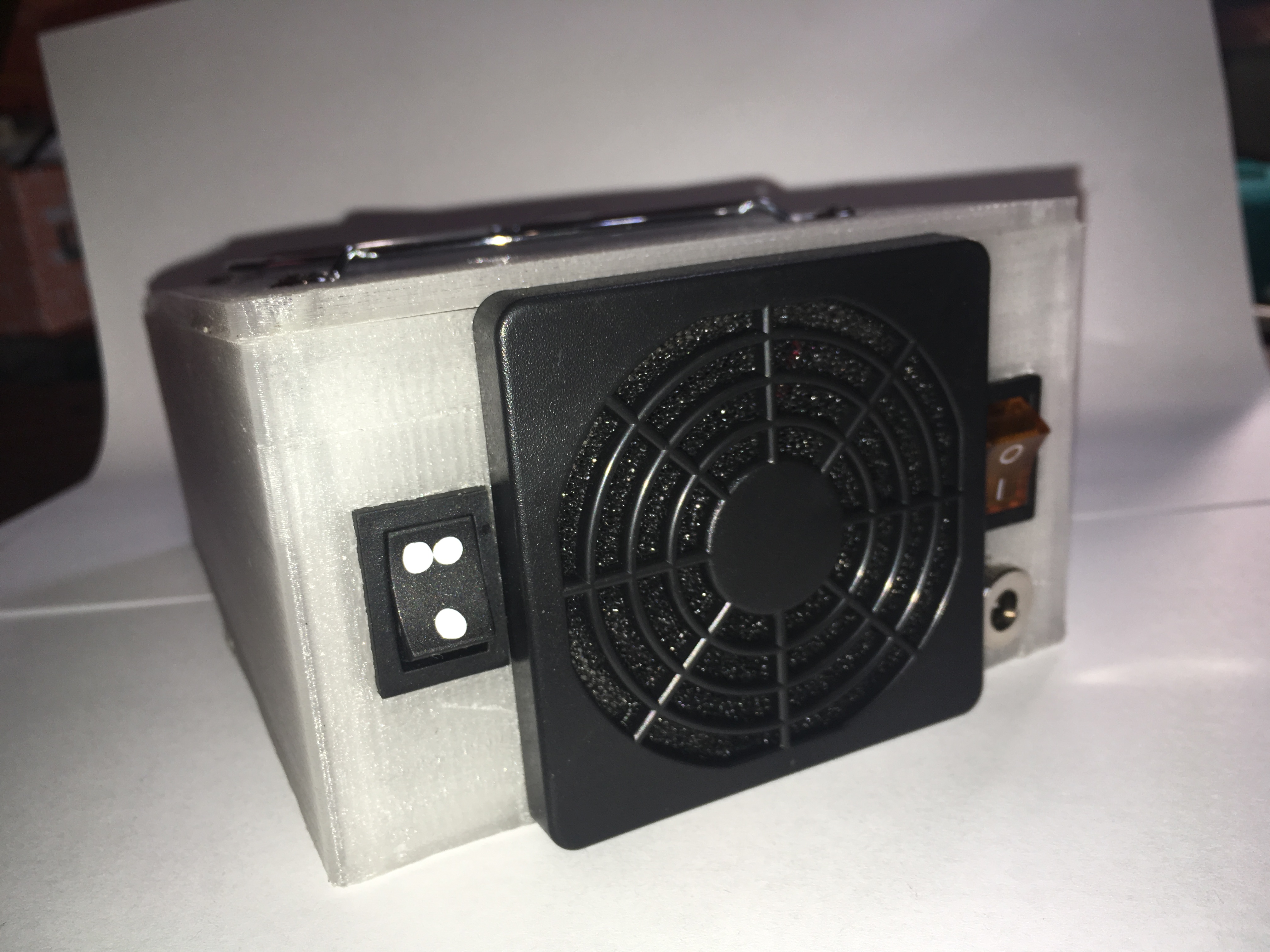
Next, solder the central positive wire to the central pin of the connector. Next, we connect the positive wire from the fans to the power tap of the mode switch button and the power supply wire and mount the button into the case.
Now we unzip the on / off button of the device. My button has 4 contacts, this is necessary for breaking and plus and minus output. Here you can use any other button of this size. We solder the wires to the button in advance, so that after it is more convenient to connect the button after installing it in the case.
Now you can do the power connector. Before installing the connector, it is necessary to put a nut on the wires. This is my favorite mistake, because after soldering, the nut cannot be installed.
Everything is soldered. We tighten the nut to the connector. It’s not so easy, we help ourselves with a screwdriver or tweezers. We install heat shrink on all contacts or cover them with varnish so that during operation the contacts are not shorted with debris. You never know what can get there ... Now, many decorative elements are applied to the nails, and varnishes are with metal chips, accidental contact with which can lead to a short circuit.
Now we will lay all the wires and fix them with hot glue. It is simple, quick and helps the wires not to slip away during operation.
Before the final assembly, we test the operation of our device ... This must be done in advance in order to eliminate our errors and make sure that there are no defects in the operation of our keys and connector.
The power button works. Modes are switched, everything works as it should.
Now you can tighten the upper housing cover. We will fasten with small self-tapping screws to the body of the case in plastic racks.
The final step in our work is the installation of a dust box. First of all, we’ll install a ring, for example, which is used for key rings. Install it in the handle of the box for easy opening.
Now we find a piece of fabric, for example from old socks and cut out the part we need and fasten it to the box with screws. We cut off the excess areas. The fabric will serve as a filter that will trap all of the nail dust and prevent it from reaching the exhaust fan.
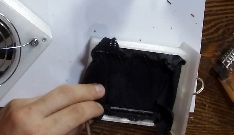
We fix the fabric in the box with a plastic bracket.
The device is working!
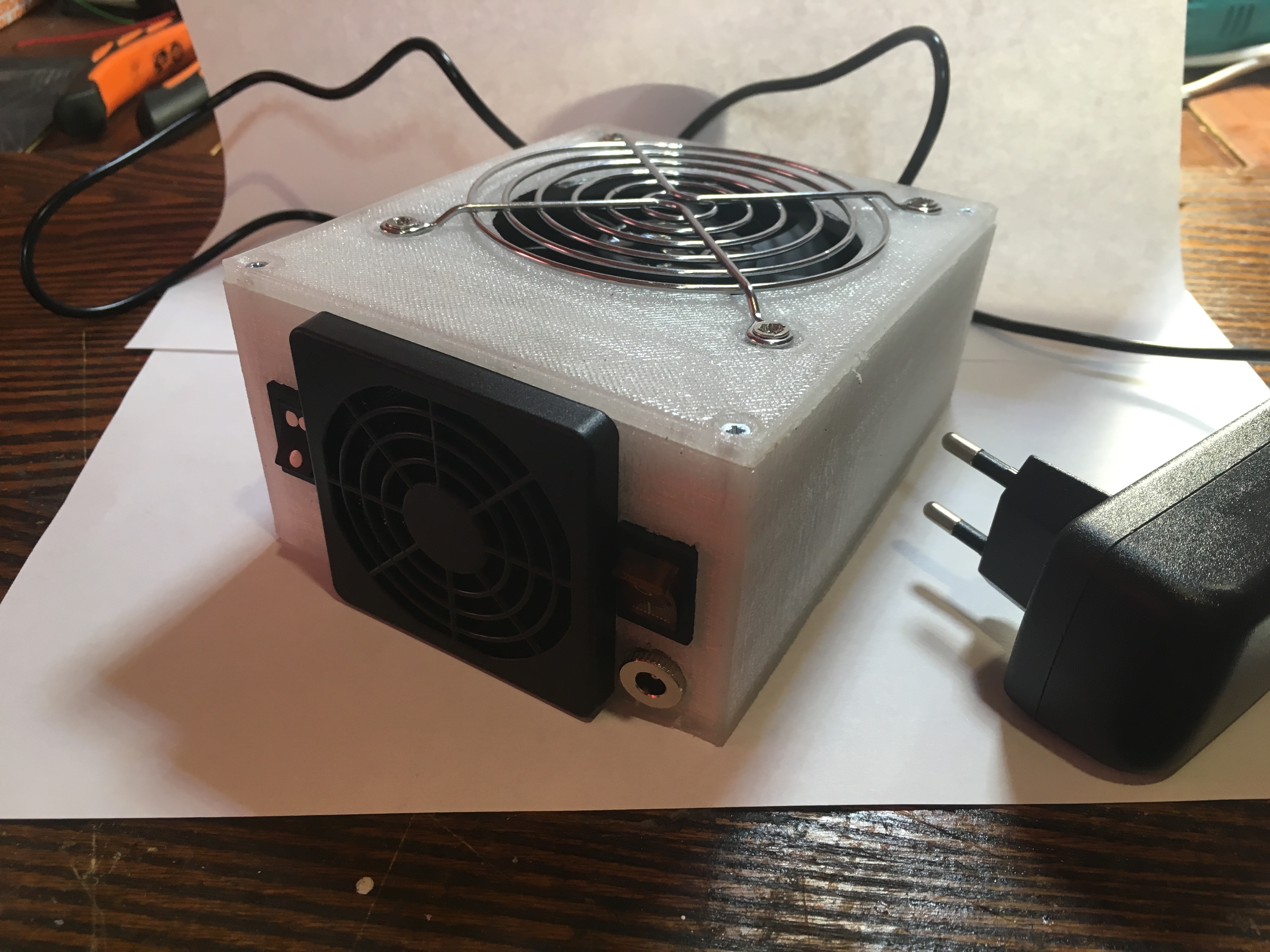
On this we can finish our work.
Assembly video:
I wish you all success! See you soon!
PS A short list of all components:
Materials:
Its main task is to draw in the nail crumb and dust, which is formed as a result of the work of the cutter.
This allows you to keep your desktop clean and not to breathe light dusty air. Similar fans can be found in any nail service. After browsing the Internet, I realized that the device is in demand and many are trying to make it themselves.
I developed a 3D model of the unit body.
We will collect it! The housing consists of 3 parts, plus a retainer. The project turned out to be budgetary, it will be useful to many beginner manicure masters.
In addition to the model printed on a 3D printer, we will need: a large 12V fan of 92 by 92 mm in size, which will serve as a retractor fan and a small one, 50 by 50 or 60 by 60 in size, which will draw air from the case.
So that the dust does not fly out of the case, and the fingers do not fall into the blades, we will use protective grilles.
On a large fan - metal with large openings:
And the exhaust fan is small with a filter of fine dust.
We also need one on / off button:
And a button to switch modes.
One resistance per 2 watts per 50 ohms.
You can use any resistance in the range from 30 to 80 Ohms, which will allow us to lower the fan speed for the second mode. As power, we need a 12V 1 or 2 amp block and a power connector on the chassis for it.
You will also need about 1 meter of wires for installation, preferably different colors and soldering accessories. It is enough to take wires of 0.5 or 0.75 section. The project can be supplemented with an end microswitch to turn off the fans when the dust compartment is opened:
... and backlight for greater effect)
I provide simple schemes for our project:
And an augmented project with limit switch and backlight:
The first thing we do is switch the mode button. At the extreme contacts, we will solder our resistance.
Such a connection will simplify the circuit and we can refuse the extra wire. The power supply is made to any of the resistance contacts on the one hand,
the power tap, which goes directly to the fans, is taken from the central contact of the mode switch key.
Next, we mount our small exhaust fan to the body, fasten it with two screws diagonally to the body.
On the reverse side we install a plastic grill with a filter. We fasten the grate with 4 screws to the box body.
Now let's install a large exhaust fan. We will fasten it together with a metal grill 92 by 92 mm to the lid of our plastic box. We will fasten the screws that were included with the fan.
These are often used for mounting fans in computer cases. You can buy them, like the fans themselves, in any computer or radio store.
Be sure to observe the air flow direction of the fans! It is worth paying attention to the selection of a large exhaust fan. The more powerful it is, the better it will be to absorb trash and it will be more comfortable to work.
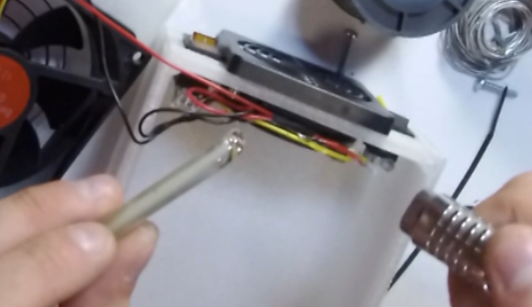
We check our dust collector so that it freely enters the case after installing the fans. Next, we need to strip the wires and connect the fans together.
If your fan has 3 wires, then we use only black and red. 3 wire just cut off, it is necessary to control the speed of the fan.
We will not complicate the project with circuits with infinitely variable speed control and will do much easier.
Next, solder the central positive wire to the central pin of the connector. Next, we connect the positive wire from the fans to the power tap of the mode switch button and the power supply wire and mount the button into the case.
Now we unzip the on / off button of the device. My button has 4 contacts, this is necessary for breaking and plus and minus output. Here you can use any other button of this size. We solder the wires to the button in advance, so that after it is more convenient to connect the button after installing it in the case.
Now you can do the power connector. Before installing the connector, it is necessary to put a nut on the wires. This is my favorite mistake, because after soldering, the nut cannot be installed.
Everything is soldered. We tighten the nut to the connector. It’s not so easy, we help ourselves with a screwdriver or tweezers. We install heat shrink on all contacts or cover them with varnish so that during operation the contacts are not shorted with debris. You never know what can get there ... Now, many decorative elements are applied to the nails, and varnishes are with metal chips, accidental contact with which can lead to a short circuit.
Now we will lay all the wires and fix them with hot glue. It is simple, quick and helps the wires not to slip away during operation.
Before the final assembly, we test the operation of our device ... This must be done in advance in order to eliminate our errors and make sure that there are no defects in the operation of our keys and connector.
The power button works. Modes are switched, everything works as it should.
Now you can tighten the upper housing cover. We will fasten with small self-tapping screws to the body of the case in plastic racks.
The final step in our work is the installation of a dust box. First of all, we’ll install a ring, for example, which is used for key rings. Install it in the handle of the box for easy opening.
Now we find a piece of fabric, for example from old socks and cut out the part we need and fasten it to the box with screws. We cut off the excess areas. The fabric will serve as a filter that will trap all of the nail dust and prevent it from reaching the exhaust fan.
We fix the fabric in the box with a plastic bracket.
The device is working!
On this we can finish our work.
Assembly video:
I wish you all success! See you soon!
PS A short list of all components:
Materials:
- 12V fan 92x92 and 50x50 or 60x60 12V
- Protective metal grill 120x120
- Power connector in the housing 2.1x5.5
- Power supply 12V on 1 or 2 A with 2.1x5.5 connector
- On / off button, for example kcd1-104 and switching modes (without zero position) kc3 or kcd1
- Resistance 2 W 50 Ohms (any from 30-70 Ohms is possible).
- Optionally, the end microswitch is the simplest (most often green) with a roller, the smallest one. A piece of 12V LED strip. The tape is relevant only for translucent plastic, for example sbs-glass.
- Wires, soldering supplies and a little patience.
- A small piece of fabric and a key ring
- Case for model
All Articles