Unity Interactive Map Shaders
This tutorial is about interactive maps and creating them in Unity using shaders.
This effect can serve as the basis for more complex techniques, such as holographic projections or even a sand table from the movie "Black Panther".
The source of inspiration for this tutorial is the tweet published by Baran Kahyaoglu , showing an example of what he is creating for Mapbox .
The scene (excluding the map) was taken from the Unity Visual Effect Graph Spaceship demo (see below), which can be downloaded here .
Part 1. Vertex Offset
Anatomy of effect
The first thing you can immediately notice is that geographical maps are flat : if they are used as textures, then they lack the three-dimensionality that a real 3D model of the corresponding map area would have.
You can apply this solution: create a 3D model of the area that is needed in the game, and then apply a texture from the map to it. This will help to solve the problem, but it takes a lot of time and does not allow to realize the effect of “scrolling” from the Baran Kahyaoglu video.
Obviously, a more technical approach is best. Fortunately, shaders can be used to change the geometry of a 3D model. With their help, you can turn any plane into valleys and mountains of the area we need.
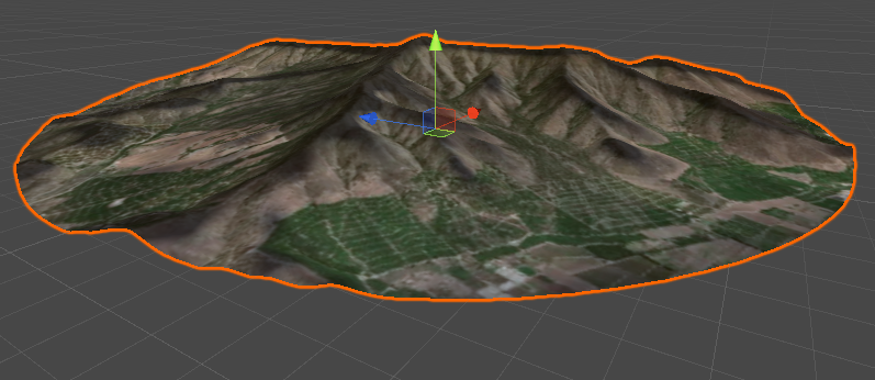
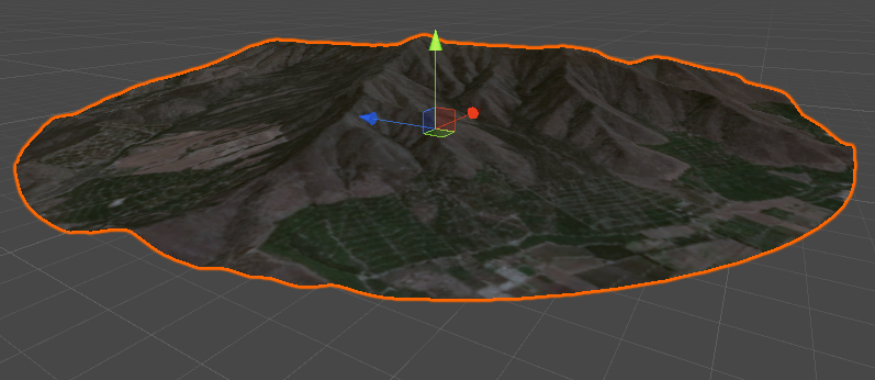
In this tutorial we use a map of Quillota in Chile, famous for its characteristic hills. The image below shows the texture of the region plotted on a round mesh.
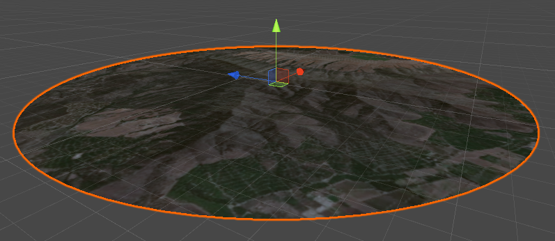
Although we see hills and mountains, they are still completely flat. This destroys the illusion of realism.
Extruding normals
The first step to using shaders to change the geometry is a technique called normal extrusion . She needs a vertex modifier : a function that can manipulate individual vertices of a 3D model.
The way the vertex modifier is used depends on the type of shader used. In this tutorial, we will change the Surface Standard Shader , one of the types of shaders that you can create in Unity.
There are many ways to manipulate the vertices of a 3D model. One of the very first methods described in most vertex shader tutorials is extruding normals . It consists in pushing each vertex “out” ( extruding ), which gives the 3D model a more bloated look. “Outside” means that each vertex moves along the direction of the normal.
For smooth surfaces, this works very well, but in models with poor vertex connections, this method can create strange artifacts. This effect is well explained in one of my first tutorials: A Gentle Introduction to Shaders , where I showed how to extrude and intrude a 3D model.
Adding extruded normals to a surface shader is very easy. Each surface shader has a
#pragma
, which is used to transmit additional information and commands. One such command is
vert
, which means that the
vert
function will be used to process each vertex of the 3D model.
The edited shader is as follows:
#pragma surface surf Standard fullforwardshadows addshadow vertex:vert ... float _Amount; ... void vert(inout appdata_base v) { v.vertex.xyz += v.normal * _Amount; }
Since we are changing the position of the vertices, we also need to use
addshadow
if we want the model to correctly cast shadows on itself.
What is appdata_base?
As you can see, we have added the function of vertices modifier (
), which takes as a parameter a structure called
. This structure stores information about each individual vertex of the 3D model. It contains not only the vertex position (
), but also other fields, for example , the normal direction (
) and texture information associated with the vertex (
).
In some cases, this is not enough and we may need other properties, such as vertex color (
) and tangent direction (
). Vertex modifiers can be specified using a variety of other inbound structures, including
and
, which provide more information at the cost of low performance
. Read more about
(and its variants) in the Unity3D wiki .
vert
), which takes as a parameter a structure called
appdata_base
. This structure stores information about each individual vertex of the 3D model. It contains not only the vertex position (
v.vertex
), but also other fields, for example , the normal direction (
v.normal
) and texture information associated with the vertex (
v.texcoord
).
In some cases, this is not enough and we may need other properties, such as vertex color (
v.color
) and tangent direction (
v.tangent
). Vertex modifiers can be specified using a variety of other inbound structures, including
appdata_tan
and
appdata_full
, which provide more information at the cost of low performance
appdata_full
. Read more about
appdata
(and its variants) in the Unity3D wiki .
How are values returned from vert?
The top function has no return value. If you are familiar with the C # language, you should know that structures are passed by value, that is, when
changes
this only affects the copy of
, the scope of which is limited by the body of the function.
However,
also declared as
, which means that it is used for both input and output. Any changes you make change the variable itself, which we pass to
. The keywords
and
very often used in computer graphics, and they can roughly be correlated with
and
in C #.
v.vertex
changes
v.vertex
this only affects the copy of
v
, the scope of which is limited by the body of the function.
However,
v
also declared as
inout
, which means that it is used for both input and output. Any changes you make change the variable itself, which we pass to
vert
. The keywords
inout
and
out
very often used in computer graphics, and they can roughly be correlated with
ref
and
out
in C #.
Extruding normals with textures
The code we used above works correctly, but it is far from the effect that we want to achieve. The reason is that we do not want to extrude all the vertices by the same amount. We want the surface of the 3D model to match the valleys and mountains of the corresponding geographic region. First, we somehow need to store and retrieve information about how much each point on the map is raised. We want extruding to be influenced by the texture in which the heights of the landscape are encoded. Such textures are often referred to as heightmaps , but they are often referred to as depthmaps , depending on the context. Having received information about the heights, we will be able to modify the extrusion of the plane based on the height map. As shown in the diagram, this will allow us to control the raising and lowering of areas.

It’s quite simple to find a satellite image of a geographic area of interest to you and an associated elevation map. Below is a satellite map of Mars (above) and a height map (below) that were used in this tutorial:

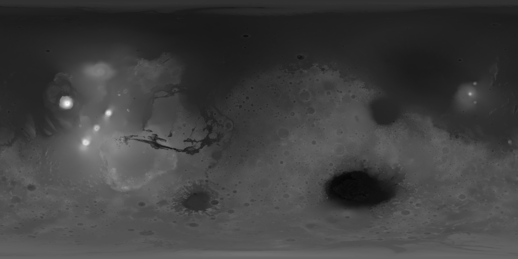
I spoke in detail about the concept of the depth map in another series of tutorials called “3D photos of Facebook from the inside: parallax shaders” [ translation into Habré].
In this tutorial, we will assume that the height map is stored as an image in grayscale, where black and white correspond to lower and higher heights. We also need these values to scale linearly , that is, the color difference, for example, at
0.1
corresponds to a height difference between
0
and
0.1
or between
0.9
and
1.0
. For depth maps, this is not always true, because many of them store depth information on a logarithmic scale .
To sample a texture, two elements of information are needed: the texture itself and the UV coordinates of the point we want to sample. The latter can be accessed through the
texcoord
field, stored in the
appdata_base
structure. This is the UV coordinate associated with the current vertex being processed. Texture sampling in a surface function is done using
tex2D
, but when we are in a
,
tex2Dlod
is required.
In the code snippet below, a texture called
_HeightMap
used to modify the extrusion value performed for each vertex:
sampler2D _HeightMap; ... void vert(inout appdata_base v) { fixed height = tex2Dlod(_HeightMap, float4(v.texcoord.xy, 0, 0)).r; vertex.xyz += v.normal * height * _Amount; }
Why can't tex2D be used as a vertex function?
If you look at the code that Unity generates for Standard Surface Shader, you can see that it already contains an example of how to sample textures. In particular, it samples the main texture (called
_MainTex
) in a surface function (called
surf
) using the built-in
tex2D
function.
And in fact,
tex2D
used to sample pixels from a texture, regardless of what is stored in it, color or height. However, you may notice that
tex2D
cannot be used in a vertex function.
The reason is that
tex2D
not only reads pixels from the texture. She also decides which version of the texture to use, depending on the distance to the camera. This technique is called mipmapping : it allows you to have smaller versions of a single texture that can be automatically used at different distances.
In the surface function, the shader already knows which MIP texture to use. This information may not yet be available in the vertex function, and therefore
tex2D
cannot be used with full confidence. In contrast, the
tex2Dlod
function can be passed two additional parameters, which in this tutorial can have a zero value.
The result is clearly visible in the images below.
In this case, one slight simplification can be made. The code we reviewed earlier can work with any geometry. However, we can assume that the surface is absolutely flat. In fact, we really want to apply this effect to the plane.
Therefore, you can remove
v.normal
and replace it with
float3(0, 1, 0)
:
void vert(inout appdata_base v) { float3 normal = float3(0, 1, 0); fixed height = tex2Dlod(_HeightMap, float4(v.texcoord.xy, 0, 0)).r; vertex.xyz += normal * height * _Amount; }
We could do this because all coordinates in
appdata_base
are stored in the model space , that is, they are set relative to the center and orientation of the 3D model. Transition, rotation and scaling with transform in Unity change the position, rotation and scale of the object, but do not affect the original 3D model.
Part 2. Scrolling Effect
Everything that we did above works pretty well. Before proceeding, we will extract the code necessary to calculate the new vertex height into a separate
getVertex
function:
float4 getVertex(float4 vertex, float2 texcoord) { float3 normal = float3(0, 1, 0); fixed height = tex2Dlod(_HeightMap, float4(texcoord, 0, 0)).r; vertex.xyz += normal * height * _Amount; return vertex; }
Then the entire function
vert
will have the form:
void vert(inout appdata_base v) { vertex = getVertex(v.vertex, v.texcoord.xy); }
We did this because in below we need to calculate the height of several points. Due to the fact that this functionality will be in its own separate function, the code will become much simpler.
UV coordinate calculation
However, this leads us to another problem. The
getVertex
function depends not only on the position of the current vertex (v.vertex), but also on its UV coordinates (
v.texcoord
).
When we want to calculate the vertex height offset that the
vert
function is currently processing, both data elements are available in the
appdata_base
structure. However, what happens if we need to sample the position of a neighboring point? In this case, we can know the position of xyz in the model space , but we do not have access to its UV coordinates.
This means that the existing system is able to calculate the height offset only for the current vertex. Such a restriction will not allow us to move on, so we need to find a solution.
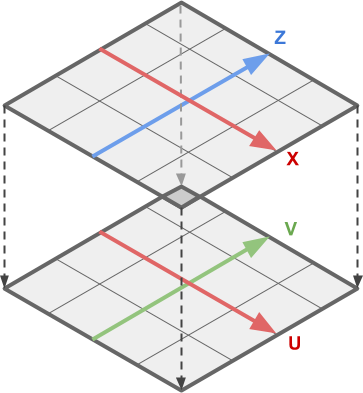
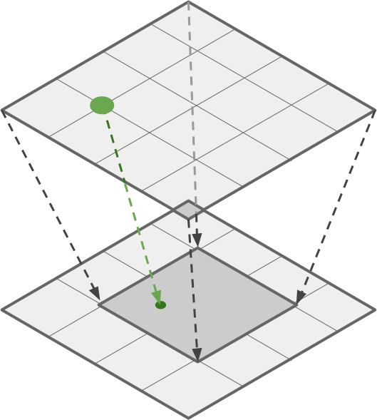
The easiest way is to find a way to calculate the UV coordinates of a 3D object, knowing the position of its vertex. This is a very difficult task, and there are several techniques for solving it (one of the most popular is triplanar projection ). But in this particular case, we do not need to match UV with geometry. If we assume that the shader will always be applied to the flat mesh, then the task becomes trivial.
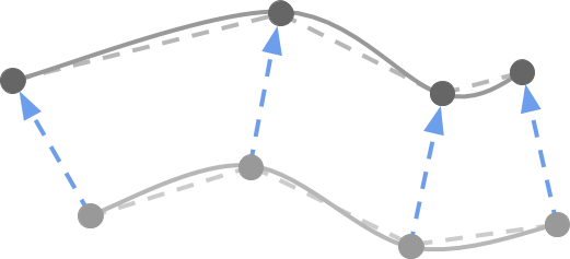
We can calculate UV-coordinates (lower image) from the positions of the vertices (upper image) due to the fact that both are superimposed linearly on a flat mesh.

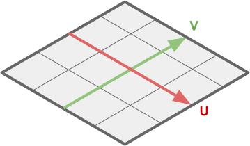
This means that to solve our problem, we need to transform the components XZ of the vertex position into the corresponding UV coordinates .
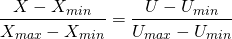
This procedure is called linear interpolation . It is discussed in detail on my website (for example: The Secrets Of Color Interpolation ).
In most cases, the UV values are in the range from before ; the coordinates of each vertex, in contrast, are potentially unlimited. From the point of view of mathematics, for the conversion from XZ to UV, we only need their limit values:
- ,
- ,
- ,
- ,
which are shown below:

These values vary depending on the mesh used. On the Unity plane, UV coordinates are between before , and the coordinates of the vertices are in the range from before .
The equations for converting XZ to UV are:
(one)

How are they displayed?
If you are unfamiliar with the concept of linear interpolation, then these equations may seem pretty scary.
However, they are displayed quite simply. Let's look at just an example. . We have two intervals: one has values from before another from before . Incoming data for the coordinate is the coordinate of the current vertex being processed, and the output will be the coordinate used to sample the texture.
We need to maintain the properties of proportionality between and its interval, and and its interval. For example, if matters 25% of its interval then will also matter 25% of its interval.
All this is shown in the following diagram:

From this we can deduce that the proportion made up of the red segment with respect to the pink should be the same as the proportion between the blue segment and the blue:
(2)
Now we can transform the equation shown above to get :

and this equation has exactly the same form as shown above (1).
However, they are displayed quite simply. Let's look at just an example. . We have two intervals: one has values from before another from before . Incoming data for the coordinate is the coordinate of the current vertex being processed, and the output will be the coordinate used to sample the texture.
We need to maintain the properties of proportionality between and its interval, and and its interval. For example, if matters 25% of its interval then will also matter 25% of its interval.
All this is shown in the following diagram:
From this we can deduce that the proportion made up of the red segment with respect to the pink should be the same as the proportion between the blue segment and the blue:
(2)
Now we can transform the equation shown above to get :
and this equation has exactly the same form as shown above (1).
These equations can be implemented in code as follows:
float2 _VertexMin; float2 _VertexMax; float2 _UVMin; float2 _UVMax; float2 vertexToUV(float4 vertex) { return (vertex.xz - _VertexMin) / (_VertexMax - _VertexMin) * (_UVMax - _UVMin) + _UVMin; }
Now we can call the
getVertex
function without having to pass
v.texcoord
:
float4 getVertex(float4 vertex) { float3 normal = float3(0, 1, 0); float2 texcoord = vertexToUV(vertex); fixed height = tex2Dlod(_HeightMap, float4(texcoord, 0, 0)).r; vertex.xyz += normal * height * _Amount; return vertex; }
Then the whole function
vert
takes the form:
void vert(inout appdata_base v) { v.vertex = getVertex(v.vertex); }
Scroll effect
Thanks to the code we wrote, the entire map is displayed on the mesh. If we want to improve the display, we need to make changes.
Let's formalize the code a bit more. Firstly, we may need to zoom in on a separate part of the map, rather than look at it whole.
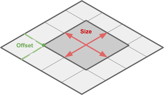
This area can be defined by two values: its size (
_CropSize
) and location on the map (
_CropOffset
), measured in vertex space (from
_VertexMin
to
_VertexMax
).
// Cropping float2 _CropSize; float2 _CropOffset;
Having received these two values, we can once again use linear interpolation so that
getVertex
called not for the current position of the top of the 3D model, but for the scaled and transferred point.
Relevant Code:
void vert(inout appdata_base v) { float2 croppedMin = _CropOffset; float2 croppedMax = croppedMin + _CropSize; // v.vertex.xz: [_VertexMin, _VertexMax] // cropped.xz : [croppedMin, croppedMax] float4 cropped = v.vertex; cropped.xz = (v.vertex.xz - _VertexMin) / (_VertexMax - _VertexMin) * (croppedMax - croppedMin) + croppedMin; v.vertex.y = getVertex(cropped); }
If we want to scroll, then it will be enough to update
_CropOffset
through the script. Due to this, the truncation area will move, actually scrolling through the landscape.
public class MoveMap : MonoBehaviour { public Material Material; public Vector2 Speed; public Vector2 Offset; private int CropOffsetID; void Start () { CropOffsetID = Shader.PropertyToID("_CropOffset"); } void Update () { Material.SetVector(CropOffsetID, Speed * Time.time + Offset); } }
For this to work, it is very important to set the Wrap Mode of all textures to Repeat . If this is not done, then we will not be able to loop the texture.
For the zoom / zoom effect, just changing
_CropSize
.
Part 3. Terrain shading
Flat shading
All the code we wrote works, but has a serious problem. The shading of the model is somehow strange. The surface is properly curved, but reacts to light as if it were flat.
This is very clearly seen in the images below. The top image shows an existing shader; the bottom shows how it actually works.
Solving this problem can be a big challenge. But first, we need to figure out what the mistake is.
The normal extrusion operation changed the general geometry of the plane that we used initially. However, Unity only changed the position of the vertices, but not their normal directions. The direction of the vertex normal , as the name implies, is a unit length vector ( direction ) indicating perpendicular to the surface. Normals are necessary because they play an important role in shading a 3D model. They are used by all surface shaders to calculate how light should be reflected from each triangle of the 3D model. This is usually needed to improve the three-dimensionality of the model, for example, it causes light to bounce off a flat surface just as it would bounce off a curved surface. This trick is often used to make low-poly surfaces look smoother than they actually are (see below).

However, in our case the opposite happens. The geometry is curved and smooth, but since all the normals are directed upwards, the light is reflected from the model as if it were flat (see below):

You can read more about the role of normals in object shading in the article on Normal Mapping (Bump Mapping) , where identical cylinders look very different, despite the same 3D model, due to different methods of calculating vertex normals (see below).


Unfortunately, neither Unity nor the language for creating shaders has a built-in solution for automatically converting normals. This means that you will have to change them manually depending on the local geometry of the 3D model.
Normal calculation
The only way to fix the shading problem is to manually calculate the normals based on the surface geometry. A similar problem was discussed in the post Vertex Displacement - Melting Shader Part 1 , where it was used to simulate the melting of 3D models in the game Cone Wars .
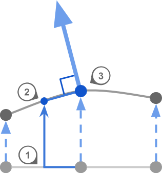
Although the finished code will have to work in 3D coordinates, let's restrict the task to only two dimensions for now. Imagine that you need to calculate the direction of the normal corresponding to the point on the 2D curve (the big blue arrow in the diagram below).
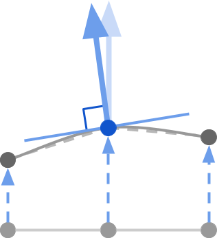
From a geometric point of view, the direction of the normal (large blue arrow) is a vector perpendicular to the tangent passing through the point of interest to us (a thin blue line). The tangent can be represented as a line located on the curvature of the model. A tangent vector is a unit vector that lies on a tangent.
This means that to calculate the normal, you need to take two steps: first find the line tangent to the desired point; then calculate the vector perpendicular to it (which will be the necessary direction of the normal ).
Tangent calculation
To get the normal, we first need to calculate the tangent . It can be approximated by sampling a point nearby and using it to build a line near the vertex. The smaller the line, the more accurate the value.
Three steps are required:
- Stage 1. Move a small amount on a flat surface
- Step 2. Calculate the height of the new point.
- Step 3. Use the height of the current point to calculate the tangent
All this can be seen in the image below:
For this to work, we need to calculate the heights of two points, not one. Fortunately, we already know how to do this. In the previous part of the tutorial, we created a function that samples the height of a landscape based on a mesh point. We called it
getVertex
.
We can take a new vertex value at the current point, and then at two others. One will be for the tangent, the other for the tangent at two points. With their help, we get the normal. If the original mesh used to create the effect is flat (and in our case it is), then we do not need access to
v.normal
and we can simply use
float3(0, 0, 1)
for tangent and tangent to two points, respectively
float3(0, 0, 1)
and
float3(1, 0, 0)
. If we wanted to do the same, but, for example, for a sphere, then finding two suitable points for calculating the tangent and the tangent to two points would be much more difficult.
Vector artwork
Having obtained the suitable tangent and tangent vectors to two points, we can calculate the normal using an operation called the vector product . There are many definitions and explanations of a vector work and what it does.
A vector product receives two vectors and returns one new. If two initial vectors were unit (their length is equal to one), and they are located at an angle of 90, then the resulting vector will be located at 90 degrees relative to both.
At first, this can be confusing, but graphically it can be represented as follows: the vector product of two axes creates a third. I.e but also , and so on.
If we take a sufficiently small step (in the code, this is
offset
), then the vectors of the tangent and tangent to two points will be at an angle of 90 degrees.Together with the normal vector, they form three perpendicular axes oriented along the surface of the model.
Knowing this, we can write all the necessary code to calculate and update the normal vector.
void vert(inout appdata_base v) { float3 bitangent = float3(1, 0, 0); float3 tangent = float3(0, 0, 1); float offset = 0.01; float4 vertexBitangent = getVertex(v.vertex + float4(bitangent * offset, 0) ); float4 vertex = getVertex(v.vertex); float4 vertexTangent = getVertex(v.vertex + float4(tangent * offset, 0) ); float3 newBitangent = (vertexBitangent - vertex).xyz; float3 newTangent = (vertexTangent - vertex).xyz; v.normal = cross(newTangent, newBitangent); v.vertex.y = vertex.y; }
Putting it all together
Now that everything is working, we can return the scroll effect.
void vert(inout appdata_base v) { // v.vertex.xz: [_VertexMin, _VertexMax] // cropped.xz : [croppedMin, croppedMax] float2 croppedMin = _CropOffset; float2 croppedMax = croppedMin + _CropSize; float4 cropped = v.vertex; cropped.xz = (v.vertex.xz - _VertexMin) / (_VertexMax - _VertexMin) * (croppedMax - croppedMin) + croppedMin; float3 bitangent = float3(1, 0, 0); float3 normal = float3(0, 1, 0); float3 tangent = float3(0, 0, 1); float offset = 0.01; float4 vertexBitangent = getVertex(cropped + float4(bitangent * offset, 0) ); float4 vertex = getVertex(cropped); float4 vertexTangent = getVertex(cropped + float4(tangent * offset, 0) ); float3 newBitangent = (vertexBitangent - vertex).xyz; float3 newTangent = (vertexTangent - vertex).xyz; v.normal = cross(newTangent, newBitangent); v.vertex.y = vertex.y; v.texcoord = float4(vertexToUV(cropped), 0,0); }
And on this our effect is finally completed.

Where to go next
This tutorial can become the basis of more complex effects, for example, holographic projections or even a copy of the sand table from the movie "Black Panther".
Unity Package
The full package for this tutorial can be downloaded on Patreon , it contains all the assets needed to play the described effect.
All Articles