OMower SDK for wheeled robots (open source, open hardware)
Finally, they got their hands on publishing the promised SDK for the OMower project (an open software and hardware platform for wheeled robots based on a 32-bit ATSAM3X8E controller with support for development in the Arduino IDE). The software completeness level is not yet very good (for example, there are no classes for bumper sensors, rain and grass, some functions are not fully debugged), but even in its current form, the robot can drive with high accuracy over RTK GPS, supports almost everything you need for mowers - sonar, wired perimeter, navigation on the compass and GPS, charging from the charging station or the solar battery.
My previous article about the project OMower
The SDK code and Kicad files with the circuit and wiring of the board rests on the githaba .
Currently, only two platforms are supported - OMower board v3 with drivers for Polulu dual MC33926 motors and a bundle of Arduino Due + IHM12A1 motor driver (a test machine on a small four-wheeled chassis). Ardumower based on Arduino Due may be added. It is highly desirable to have an IMU GY-80 board; without it, navigation does not work simply (although you can make a simple mower who accidentally drives inside the wire perimeter).
In the new, fourth version of the board, it is planned to put an IMU MPU9250 on it and add a FRAM chip to save user settings not in the internal flash of the controller (which is reset when the firmware is reloaded), well, you can also keep any cards in it. Also, probably, I will increase the sizes of resistor and capacitor assemblies, soldering 0402 “on the knee” with a hairdryer was a pleasure below average, and I will increase the space for connectors so that you can put those with clamps, not just sticking pins.
The API code is written as a handful of classes (omower - *. H files) that need to be included as objects in your software (and you do not need to include them all, you can take only those that are needed, except for the base ones). To simplify understanding and testing, the OMower_Simple manufacturer has been written, which performs a fairly large set of commands issued via pfodApp from any smartphone.
The SDK takes over the management of all low-level functions and works mainly on interrupts, which gives the programmer of the final software the ability to write software independent of specific details of a particular robot, and in a very free manner (you can write a state machine, or you can simply call the function to start driving and wait for the robot to reach the desired point). The programmer’s shoulders are borne only by the procedures for calling the functions of initialization and controlling the drive of the robot (indicating where, in fact, to go and processing the responses of sonars and other sensors).
For connecting additional external devices on the board (and support in the SDK, of course) - there are many external connectors. For example, standard servo drives with a PPM input can connect up to four pieces (or even six, if you give up two motors). There are a lot of “standard” sensors for the mower, there are six of the same sonars, and four perimeter sensors. Of course, in most cases, so much is not needed, and part of their connectors can be used to connect some other devices (almost all of the microcontroller pins are derived). The intellectual part (RTK GPS processing, connectivity with wifi) is performed by Orange PI Zero, which is installed in a special slot.
I apologize for the curve in advance and the code that was unfinished in some places, I had to turn to other projects, and many difficulties appeared that I could hardly cope with. But I learned a lot of new things, for example, that the curvature of the Earth's ellipse in our places is almost 40 meters, and the magnetic poles of the Earth wander tens of kilometers from year to year (without taking this into account, the robot traveled from point to point with very curved lines). At times it seemed that I was launching a space rocket, and not a mowing lawn. :)
Well, as a bonus, I also laid out the source of my firmware for arduinka with Decawave DW1000, which organizes a mini-network of these devices and allows the robot to determine its location inside the premises or where RTK GPS simply cannot determine its coordinates (with the support of an almost infinite number of tags and dividing into rooms). This firmware is still very, very raw, but it may be useful to someone.
Update, I decided to add an article with the story of how it’s inside there:
The SDK user must determine all the objects he needs, call the begin () function for all (hardware initialization, only once), then set the values of their parameters (by reading them from the flash or just default values), call init () for all (the function can used to reset the device for which the object is responsible), set the function of hooks for poll10 / poll20 / poll50 (10, 20 and 50 times per second) of which should call the appropriate poll * () functions of all used objects. Theoretically, it was possible to automate all this in the code of the SDK itself, but I decided not to do this because of the additional consumption of controller resources. Example of use you need to look at OMower_Simple.ino
One of the main classes is the motors object (omower-motors.h), which controls the motor drivers from its poll10 () function. The user simply calls the roll / move (turn and ride without navigation) or rollCourse / moveCourse (ride with navigation / correction data from some object, a child of the navThing class, which, through the readCourseError () functions, returns the value of the deviation from the desired direction of driving ).
Derivatives from navThing are objects of the imu and gps classes (omower-imu.h and omower-gps.h), the first is responsible for reading and converting the compass / accelerometer / gyroscope data into a convenient form (gives the compass and tilt values in degrees along two axes) ). The second one processes GPS data and guides the motors object in the right direction if driving along GPS or RTK GPS coordinates (for the latter, the correction is still calculated if the antenna is not located in the center of the robot body and a short-term correction is made using odometer sensors). The user program is responsible for communication with the actual GPS receiver and transmits NMEA strings or ready-made coordinates to the gps object.
The mow object (omower-mow.h) is responsible for the cutting motor and its actuator with stepper motor (if any). The user says how fast to rotate and what height to set.
The pwmServo object (omower-pwmservo.h) controls the PWM-A / B / C / D / E / F / G / H outputs (this cannot be done through other libraries due to possible conflicts with timers).
The power object (omower-power.h) is responsible for managing the charging regulators and converting the ADC values to volts and amps that everyone can understand. The user program must detect the appearance of voltage on the charging electrodes and call the charging on function, then it will automatically select the PWM-cycles of the regulators so that the charging current corresponds to the set one.
Since the use of standard Arduin Serial * objects can disrupt interrupt handling (see below), serial (omower-serial.h) is available for reading and transmitting serial ports. Unfortunately, I2C tires have the same problem, they should be used with the functions defined in due-i2c-blocking.h.
The functions of other objects are clear from their names, you can simply look at the comments in the header files (omower-sonars.h, omower-rtc.h, omower-current * .h, omower-odometry.h, etc.).
Now about interruptions at the lowest level. The chassis object (omower-chassis.h) configures TIM7 for 100 interrupts per second. At each interruption - 12 channels of the ADC-chip MAX11617 are read (they are entered into a special array, from where their values are read by OMower SDK objects - max11617-adc-scan.h). On every second, a soft interrupt is generated for the hook of the poll50 () functions, on every fifth - poll20 (), on every tenth - poll10 (). All of them work asynchronously (which is convenient, but imposes restrictions on the use of the I2C bus, later I plan to add some transactions / semaphores there).
Timer TIM5 is also configured to generate interrupts with a frequency of 38462 hertz. From this interrupt, all the channels of the internal ADC controller are read and entered into a special array (it also supports entering each obtained value for the selected one into the ring buffer, which makes, for example, the perimeter class, then filtering these samples using Fourier transform).
To issue debug information, there is a debug () function with a minimum priority for outputting messages (that is, while there is no debugging, nothing will be output to the console, but at any time you can enable at least the maximum level, spamming). In debugging value formats (* printf-format), floating-point numbers are supported (as opposed to standard Arduin functions).
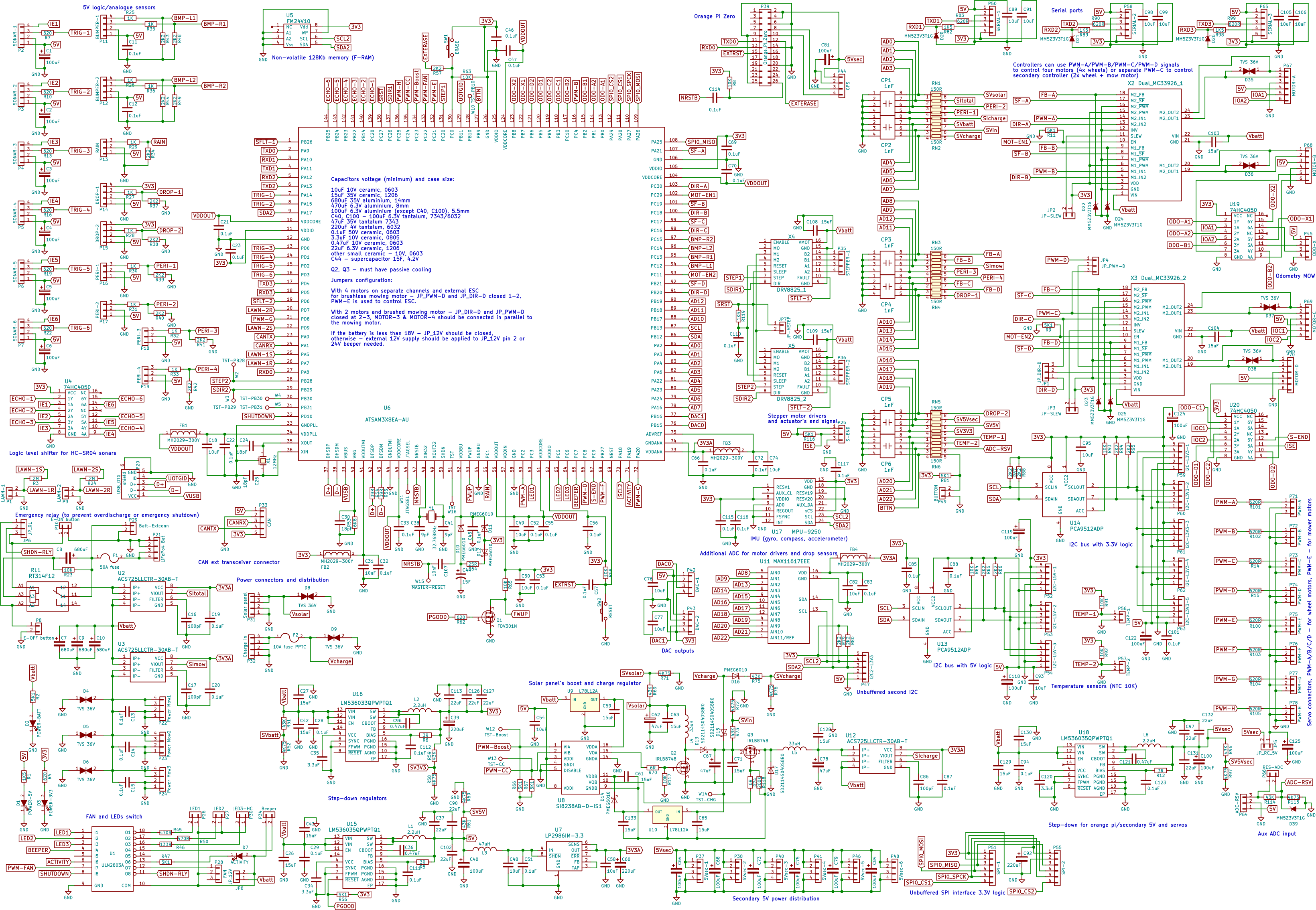
Update: The new fourth version of the OMower board, while only the scheme (waiting for PCB manufacturing). Additionally, it includes the MPU9250 compass / accelerometer, 128 kilobytes of F-RAM for saving settings, maps, waypoints and others, all connectors with latches (Molex 22-11-20x3 / 10-11-20x3, are compatible with the old versions of the 2.54- pin), 74HC4050 logic level translators for sonars and odometers, more powerful 3.3 / 5 volt power converters (up to three amps), two more PWM / PPM outputs on connectors, separate lines for independent control of the second stepper motor driver, more buffer capacitors for stability , large SMD elements to facilitate assembly minor amendments.
My previous article about the project OMower
The SDK code and Kicad files with the circuit and wiring of the board rests on the githaba .
Currently, only two platforms are supported - OMower board v3 with drivers for Polulu dual MC33926 motors and a bundle of Arduino Due + IHM12A1 motor driver (a test machine on a small four-wheeled chassis). Ardumower based on Arduino Due may be added. It is highly desirable to have an IMU GY-80 board; without it, navigation does not work simply (although you can make a simple mower who accidentally drives inside the wire perimeter).
In the new, fourth version of the board, it is planned to put an IMU MPU9250 on it and add a FRAM chip to save user settings not in the internal flash of the controller (which is reset when the firmware is reloaded), well, you can also keep any cards in it. Also, probably, I will increase the sizes of resistor and capacitor assemblies, soldering 0402 “on the knee” with a hairdryer was a pleasure below average, and I will increase the space for connectors so that you can put those with clamps, not just sticking pins.
The API code is written as a handful of classes (omower - *. H files) that need to be included as objects in your software (and you do not need to include them all, you can take only those that are needed, except for the base ones). To simplify understanding and testing, the OMower_Simple manufacturer has been written, which performs a fairly large set of commands issued via pfodApp from any smartphone.
The SDK takes over the management of all low-level functions and works mainly on interrupts, which gives the programmer of the final software the ability to write software independent of specific details of a particular robot, and in a very free manner (you can write a state machine, or you can simply call the function to start driving and wait for the robot to reach the desired point). The programmer’s shoulders are borne only by the procedures for calling the functions of initialization and controlling the drive of the robot (indicating where, in fact, to go and processing the responses of sonars and other sensors).
For connecting additional external devices on the board (and support in the SDK, of course) - there are many external connectors. For example, standard servo drives with a PPM input can connect up to four pieces (or even six, if you give up two motors). There are a lot of “standard” sensors for the mower, there are six of the same sonars, and four perimeter sensors. Of course, in most cases, so much is not needed, and part of their connectors can be used to connect some other devices (almost all of the microcontroller pins are derived). The intellectual part (RTK GPS processing, connectivity with wifi) is performed by Orange PI Zero, which is installed in a special slot.
I apologize for the curve in advance and the code that was unfinished in some places, I had to turn to other projects, and many difficulties appeared that I could hardly cope with. But I learned a lot of new things, for example, that the curvature of the Earth's ellipse in our places is almost 40 meters, and the magnetic poles of the Earth wander tens of kilometers from year to year (without taking this into account, the robot traveled from point to point with very curved lines). At times it seemed that I was launching a space rocket, and not a mowing lawn. :)
Well, as a bonus, I also laid out the source of my firmware for arduinka with Decawave DW1000, which organizes a mini-network of these devices and allows the robot to determine its location inside the premises or where RTK GPS simply cannot determine its coordinates (with the support of an almost infinite number of tags and dividing into rooms). This firmware is still very, very raw, but it may be useful to someone.
Update, I decided to add an article with the story of how it’s inside there:
The SDK user must determine all the objects he needs, call the begin () function for all (hardware initialization, only once), then set the values of their parameters (by reading them from the flash or just default values), call init () for all (the function can used to reset the device for which the object is responsible), set the function of hooks for poll10 / poll20 / poll50 (10, 20 and 50 times per second) of which should call the appropriate poll * () functions of all used objects. Theoretically, it was possible to automate all this in the code of the SDK itself, but I decided not to do this because of the additional consumption of controller resources. Example of use you need to look at OMower_Simple.ino
One of the main classes is the motors object (omower-motors.h), which controls the motor drivers from its poll10 () function. The user simply calls the roll / move (turn and ride without navigation) or rollCourse / moveCourse (ride with navigation / correction data from some object, a child of the navThing class, which, through the readCourseError () functions, returns the value of the deviation from the desired direction of driving ).
Derivatives from navThing are objects of the imu and gps classes (omower-imu.h and omower-gps.h), the first is responsible for reading and converting the compass / accelerometer / gyroscope data into a convenient form (gives the compass and tilt values in degrees along two axes) ). The second one processes GPS data and guides the motors object in the right direction if driving along GPS or RTK GPS coordinates (for the latter, the correction is still calculated if the antenna is not located in the center of the robot body and a short-term correction is made using odometer sensors). The user program is responsible for communication with the actual GPS receiver and transmits NMEA strings or ready-made coordinates to the gps object.
The mow object (omower-mow.h) is responsible for the cutting motor and its actuator with stepper motor (if any). The user says how fast to rotate and what height to set.
The pwmServo object (omower-pwmservo.h) controls the PWM-A / B / C / D / E / F / G / H outputs (this cannot be done through other libraries due to possible conflicts with timers).
The power object (omower-power.h) is responsible for managing the charging regulators and converting the ADC values to volts and amps that everyone can understand. The user program must detect the appearance of voltage on the charging electrodes and call the charging on function, then it will automatically select the PWM-cycles of the regulators so that the charging current corresponds to the set one.
Since the use of standard Arduin Serial * objects can disrupt interrupt handling (see below), serial (omower-serial.h) is available for reading and transmitting serial ports. Unfortunately, I2C tires have the same problem, they should be used with the functions defined in due-i2c-blocking.h.
The functions of other objects are clear from their names, you can simply look at the comments in the header files (omower-sonars.h, omower-rtc.h, omower-current * .h, omower-odometry.h, etc.).
Now about interruptions at the lowest level. The chassis object (omower-chassis.h) configures TIM7 for 100 interrupts per second. At each interruption - 12 channels of the ADC-chip MAX11617 are read (they are entered into a special array, from where their values are read by OMower SDK objects - max11617-adc-scan.h). On every second, a soft interrupt is generated for the hook of the poll50 () functions, on every fifth - poll20 (), on every tenth - poll10 (). All of them work asynchronously (which is convenient, but imposes restrictions on the use of the I2C bus, later I plan to add some transactions / semaphores there).
Timer TIM5 is also configured to generate interrupts with a frequency of 38462 hertz. From this interrupt, all the channels of the internal ADC controller are read and entered into a special array (it also supports entering each obtained value for the selected one into the ring buffer, which makes, for example, the perimeter class, then filtering these samples using Fourier transform).
To issue debug information, there is a debug () function with a minimum priority for outputting messages (that is, while there is no debugging, nothing will be output to the console, but at any time you can enable at least the maximum level, spamming). In debugging value formats (* printf-format), floating-point numbers are supported (as opposed to standard Arduin functions).
Update: The new fourth version of the OMower board, while only the scheme (waiting for PCB manufacturing). Additionally, it includes the MPU9250 compass / accelerometer, 128 kilobytes of F-RAM for saving settings, maps, waypoints and others, all connectors with latches (Molex 22-11-20x3 / 10-11-20x3, are compatible with the old versions of the 2.54- pin), 74HC4050 logic level translators for sonars and odometers, more powerful 3.3 / 5 volt power converters (up to three amps), two more PWM / PPM outputs on connectors, separate lines for independent control of the second stepper motor driver, more buffer capacitors for stability , large SMD elements to facilitate assembly minor amendments.
All Articles