Software emulation of the Modbus RTU network
Introduction
If you have only a hammer as a tool, every problem begins to resemble a nail.
Abraham Maslow
Modbus protocol is widely known both to readers of Habr, and to readers of giktimes. Many publications are devoted to its application, which are difficult to enumerate due to the fact that there are a lot of them, and periodically new articles appear here and there.

The popularity of this protocol is due to its openness and simplicity. The scope of applicability is quite broad: from professional industrial automation systems to amateur DIY projects of distributed control systems, smart homes, and so on. This protocol was also chosen by me when my team was engaged in the creation of software for an electric train simulator. The Modbus RTU protocol on the RS485 physical interface is used on this simulator to provide input to the control computer of data from the controls mounted on the driver's console (do not think that Modbus is used on real rolling stock!).
There is no need to talk about the difficulties involved in setting up software that interacts with a network of controllers that control equipment. Especially when part of the device already exists in the gland, and the other part is in the process of development and manufacturing. At the same time, top-level software is required to be written in view of its interaction with this hardware. And it is desirable to write it in such a way as to create a working version of the system right away, without using “crutches” which are always difficult to clean out of the code.
“We need to write software when working prototypes of all hardware are ready,” you will say, and you will be right, but ... ha-ha-ha, in the real world this rarely happens. And this is where software emulators come to the rescue.
1. Briefly about Modbus RTU
I will not talk in detail about the protocol. Those who are interested in the details can use the search - the protocol is open, its official specification and a lot of information is available on the net. Let me just say that in Modbus RTU describes the binary format of the transmitted data and as the transmission medium uses the differential twisted pair of the RS485 standard. RS232 can also be used if there is one transmitter and one receiver in the network, or RS422 for unidirectional data transmission.
We will be interested in RS485, which is a half-duplex interface, which allows only one data transmitting device at a time. Bus arbitration in Modbus is carried out by exposing a mandatory silence interval of 3.5 characters in length at a given transmission rate. Each message must begin and end with a silence interval. In the network there is one master device (master) and several slave devices (slave) (up to 31 in one network segment, without the use of repeaters). Each slave has a unique ID (from 1 to 31). Data transfer by slaves is carried out only if the master sent a request for receiving data from this device.
A typical wizard query looks like this.
| ID | Function code | Data address | Amount of data (2 bytes) | Data | CRC16 |
CRC16 is used to monitor the integrity of the transmitted data. Modus uses Big Endian data representation notation: for values of 2 bytes, the high byte within the message goes first). The protocol uses four data types:
- Coils - discrete outputs (1 bit) available for reading / writing
- Discrete inputs - discrete inputs (1 bit) available for reading
- Holding registers - output registers (2 bytes) available for reading / writing
- Input registers - input registers (2 bytes) available for reading
In response to the request, the slave sends data in the following format
| ID | Function code | The amount of data in bytes | Data | CRC16 |
The message received from the master enters the receiving buffer of all devices. However, if the first byte of the receive buffer does not match the device ID, it ignores the received data, clearing the receive buffer. If the message is intended for this device, then it forms a response and, maintaining the interval of silence, sends it to the master.
As they say, simply, but with taste. You can read more about all this in the official protocol specification . On the methods of implementing the protocol on the serial interface read here . We are not here for this.
When developing top-level software (master implemented on a PC, for example) for such a network, it would be nice to have a set of software tools that allow you to implement such a concept

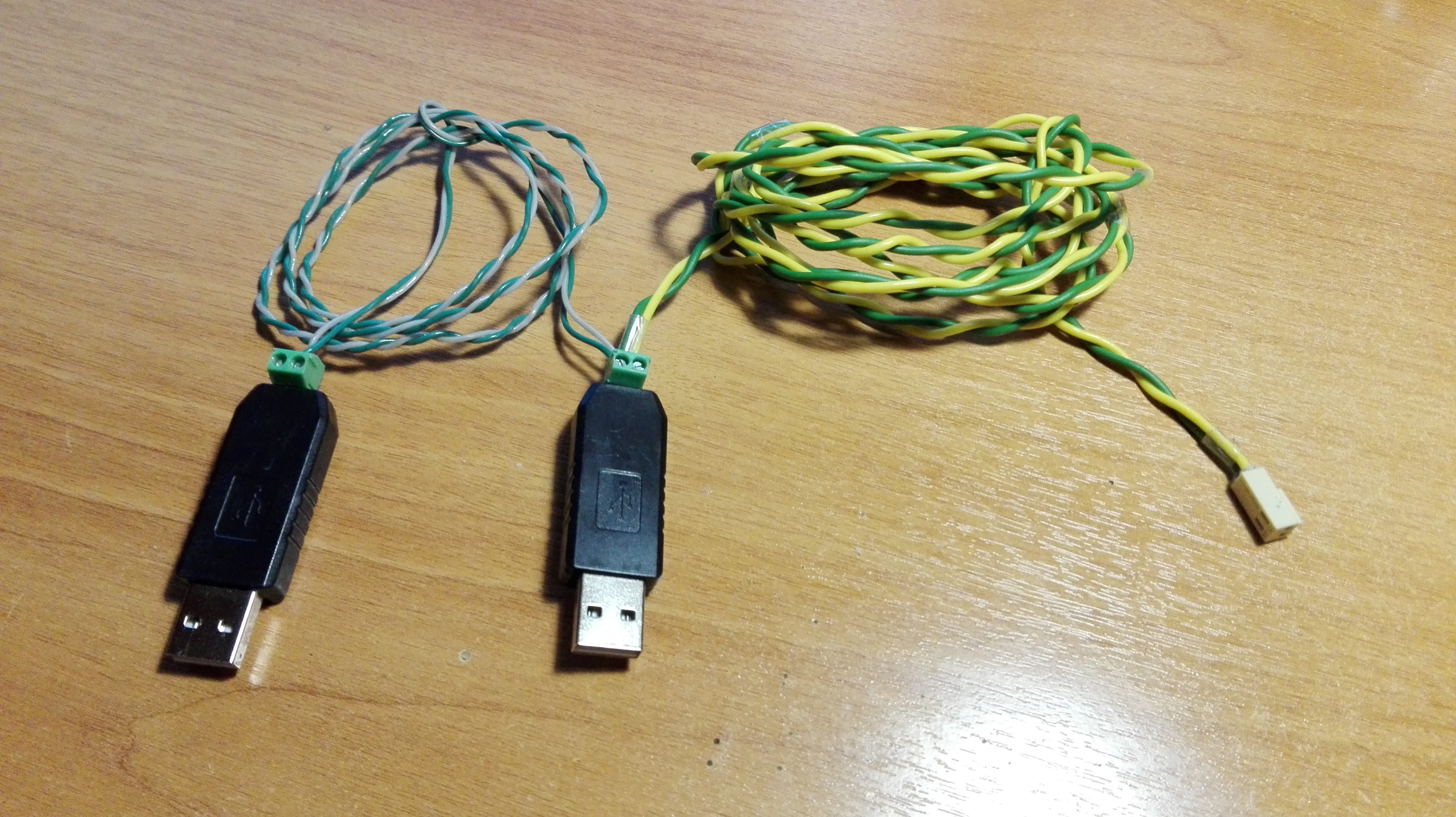
The meaning of this scheme is as follows. Suppose we have a part of the devices included in the future network. Or while there is no such device. But there is a burning desire to write software for the top level of management, to debug it, so that when the network is implemented by hardware, we don’t have to rewrite anything. To do this, you will have to use a physical transmission medium, for which we use a device like this

One of the adapters is used to connect the software developed by the wizard. The other is for connecting the emulator of the future network of slaves. We connect the part of the network that is already implemented in hardware to the tap with the white connector. Thus, we are able to safely work with the standard communication protocol, gradually introducing the real equipment into operation. In addition, by giving the object to the customer, we do not lose the opportunity to modify its software in a comfortable laboratory environment without access to the object. QSlave on the scheme is just the same part of the network, emulated by software. Naturally, you have to write the appropriate software, which was done by the author.
2. QSlave - Slave Network Emulation
QSlave is an open, cross-platform Modbus RTU network emulator. You can get it under license GPL v2.0 on Github by the above link.

The application is developed in C ++ using the Qt framework. Qt, generally speaking, has libraries for working with Modbus , but the specificity of the task — simulating a network of slaves rather than a single slave, led to the fact that the Qt built-in libraries for Modbus were not used here. A modbus self-written library was created to process data received from the virtual serial port. The code of this library is implemented as a separate project, is completely independent of the user interface and can be used for the consciousness of software simulations with more advanced functionality. Due to the fact that Modbus emulation is decoupled from the UI, the network is configured using configuration files. The XML format was chosen (we often use it in our projects). A sample configuration is available in the project code . A set of configs consists of a main file with the extension * .net, which looks like this
example.net
<?xml version="1.0" encoding="UTF-8" ?> <Config> <Slave> <!-- , --> <Description>Traffic light</Description> <!-- --> <id>1</id> <!-- XML- ( *.xml) --> <config>traffic-light</config> </Slave> </Config>
and XML configuration files for each of the slaves
traffic-light.xml
<?xml version="1.0" encoding="UTF-8" ?> <Config> <!-- --> <Coil> <address>16</address> <description>Red signal</description> <value>0</value> </Coil> <Coil> <address>17</address> <description>Yellow signal</description> <value>0</value> </Coil> <Coil> <address>18</address> <description>Green signal</description> <value>0</value> </Coil> <!-- --> <DiscreteInput> <address>0</address> <description>Ready</description> <value>1</value> </DiscreteInput> <!-- --> <HoldingRegister> <address>5</address> <description>Signal activity time</description> <value>15</value> </HoldingRegister> <!-- --> <InputRegister> <address>2</address> <description>Signals count</description> <value>3</value> </InputRegister> </Config>
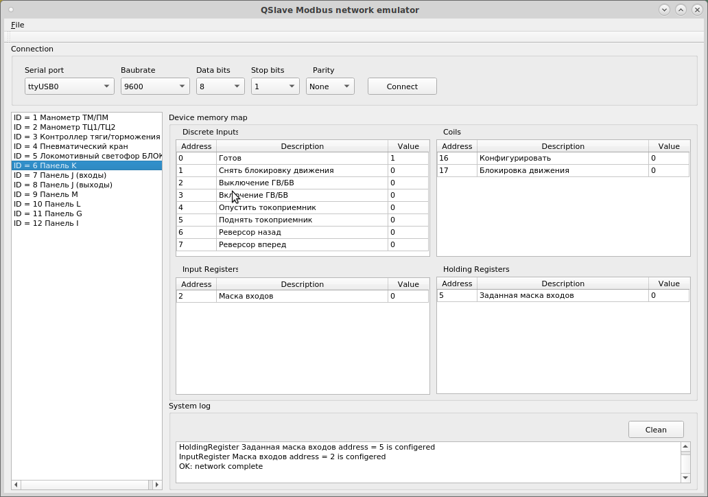
The latest file contains a description of all data available in the device. In order to load the configuration, you must open the * .net file from the QSlave program menu (File → Open config). All configuration files must be in the same directory. The example configuration describes a network from one slave device, a virtual traffic light, the discrete outputs of which describe signals, a discrete input indicates a certain device readiness bit (Ready), the input register reports the number of traffic lights, and the output register sets the time during which each of the signals.

Naturally, this simulator does not imitate the internal logic of the device operation. It only allows you to set the values of the memory cells available to the master. Any of the values can be set at your discretion by editing the corresponding table cell.
For all its simplicity, this software helps us to work on the simulator software (which has already been commissioned) without leaving the laboratory.

But no one says that you can not create a more advanced emulator that simulates the operation of virtual network devices. To create it, you can use the modbus library code, available in the QSlave package.
3. QMaster - master device emulation
To create slave devices, debug their firmware you need an imitation wizard. There are a number of open emulators, such as QModbus, for example. We used it in our work, until we decided to increase the data transfer rate to 250 kbps. QModbus does not allow this. He managed to rebuild from source under Linux, but our electronics engineers are sitting on Windows, and where the assembly did not go for a number of reasons. It turned out that this application is written in Qt 4, it uses the third-party libmodbus library. I wanted to have a cross-platform solution for Qt5, especially since Qt5 is already working out of the box with Modbus. Therefore, an analog was written using the Qt Modbus library stack - QMaster . It is also available on Github under the same conditions.

Conclusion
In conclusion, I say that I work (at work) mainly on closed projects. However, the described tools were developed by me personally in an initiative manner in my free time. In addition, they, in the Windows version, are statically linked with the Qt GPL code, so I am obliged to transfer them to the community under the same conditions as I received Qt. In addition, these tools can be useful to the reader.
Thank you for attention!
All Articles