Fischertechnik TXT Discovery Set Designer - Brief Overview
In a previous publication, I presented an overview of the history of fischertechnik engineering designers from 1965 to 2017 and now, in accordance with the wishes of readers, I post an overview of the design set 524328 ROBOTICS TXT Discovery set.

Designer 524328 is designed for boys and girls who are interested in mechanics, automation, programming, computer vision, or, as they say now, in robotics.
The cardboard box contains mechanical parts, motors, programmable TXT controller, video camera, ROBO Pro software, assembly instructions, and a small book in PDF format with educational material.
In addition to working with the designer, we need a 34969 battery set, which includes a NiMH battery and a charger.
However, before I proceed to the detailed description of the kit, I suggest that you familiarize yourself with the history of the emergence of the first fischertechnik designer devoted to robotics.
Prehistory
The first designer based on the details of fischertechnik, dedicated to mobile robotics, appeared in 1983 as part of an experimental educational project held at that time in the UK.
The company Economatics, who worked on the project, drew attention to the work of a young scientist from MIT Seymour Papert (1928-2016), who, predicting the scale of the impending revolution in the field of computer technology, suggested starting familiarizing children with computers from an early age using the educational programming language Logo .
An important feature of the Logo was the friendly interface of the execution environment and the presence in this environment of a virtual control object — a graphic “bug”, which, in accordance with the instructions of the compiled program, could move around the computer screen, leaving a trail. By the way, this paper by Mr. Papert has been transformed many times and has reached our days in the form of an educational programming environment called Scratch (we will talk about this separately later).
So, in the solution that was proposed as a result, it was proposed to replace the virtual bug with a very real object - a mobile cart. Thus, students had the opportunity not only to get acquainted with programming technologies, but also to learn the basics of robotics. So the first BBC Buggy set appeared:
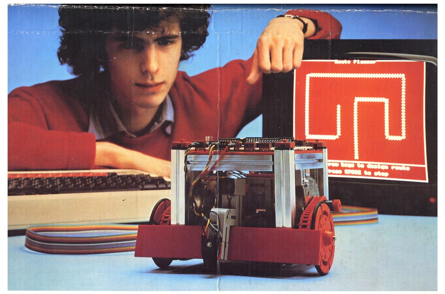
The kit included fischertechnik parts for cart assembly, a control board, a carrier with examples of control programs, and instructions with training tasks. The control board was connected to the computer using a flat cable. We can say that it was a joint project fischertechnik + Economatics.
The first completely own set for experiments with robots was released by fischertechnik in 1987 - it was the designer of 39502 Computing-Experimental. From the set it was possible to build several variants of automatic machines and try your hand at programming control algorithms.
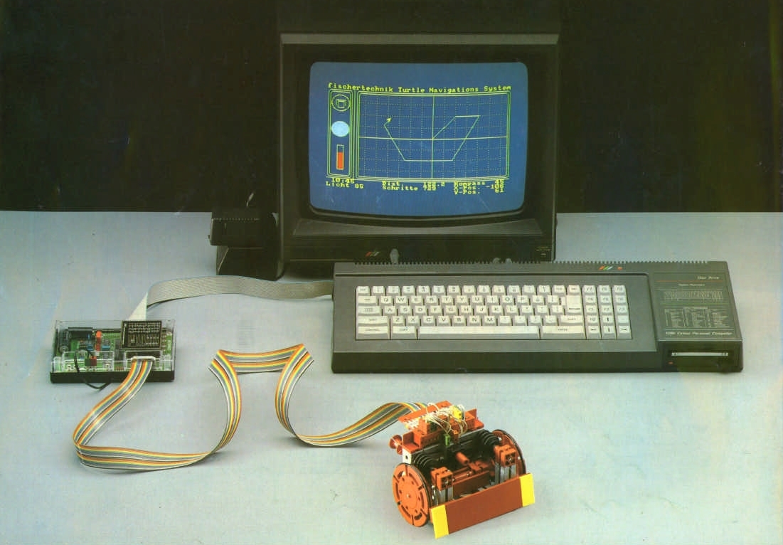
Then came the next generation of designers and additional kits for functional expansion, but this is already a story that requires a separate article. Today, I propose to take a closer look at the current set - 524328 ROBOTICS TXT Discovery set
524328 ROBOTICS TXT Discovery set
Designer 524328 consists of 310 parts, of which 14 models for experiments can be built. In addition to the assembly instructions and the CD with the ROBO Pro software, the box also contains blanks for assembling the testing ground for mobile robots. Traditionally, the set is accompanied by a mini-book in PDF format, from which you can get basic information from the field of robotics.
Appearance of packaging:

Inside the carton, parts are stored in two plastic cradles in separate compartments. If desired, you can additionally purchase a proprietary storage system and use substrates to sort parts that are easily cut with scissors from the assembly instructions.
For use in circles and schools, this designer is packaged in more convenient and durable plastic containers Gratnells and has another order number - 533018.

In addition to simple structural elements, the parts list includes two servomotors with built-in encoders, one conventional DC motor with an external gear, a phototransistor, a thermistor, tires, LEDs, and an orange ball for experiments with a computer vision system:
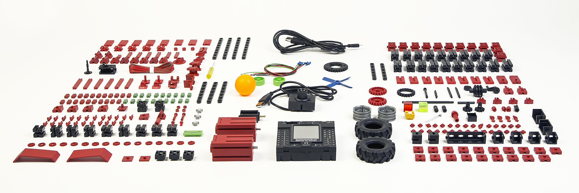
(by clicking on the picture - highres)
Programmable TXT Controller
The control unit in the constructor 524328 is designed as a compact computer based on the ARM Cortex A8 processor and the integrated I / O board on the ARM Cortex M3. For user interaction, the unit has a 2.4 inch color display, 320x240, with backlight. In addition, the computer has a built-in speaker and RTC with backup power from a lithium battery.
TXT Controller:
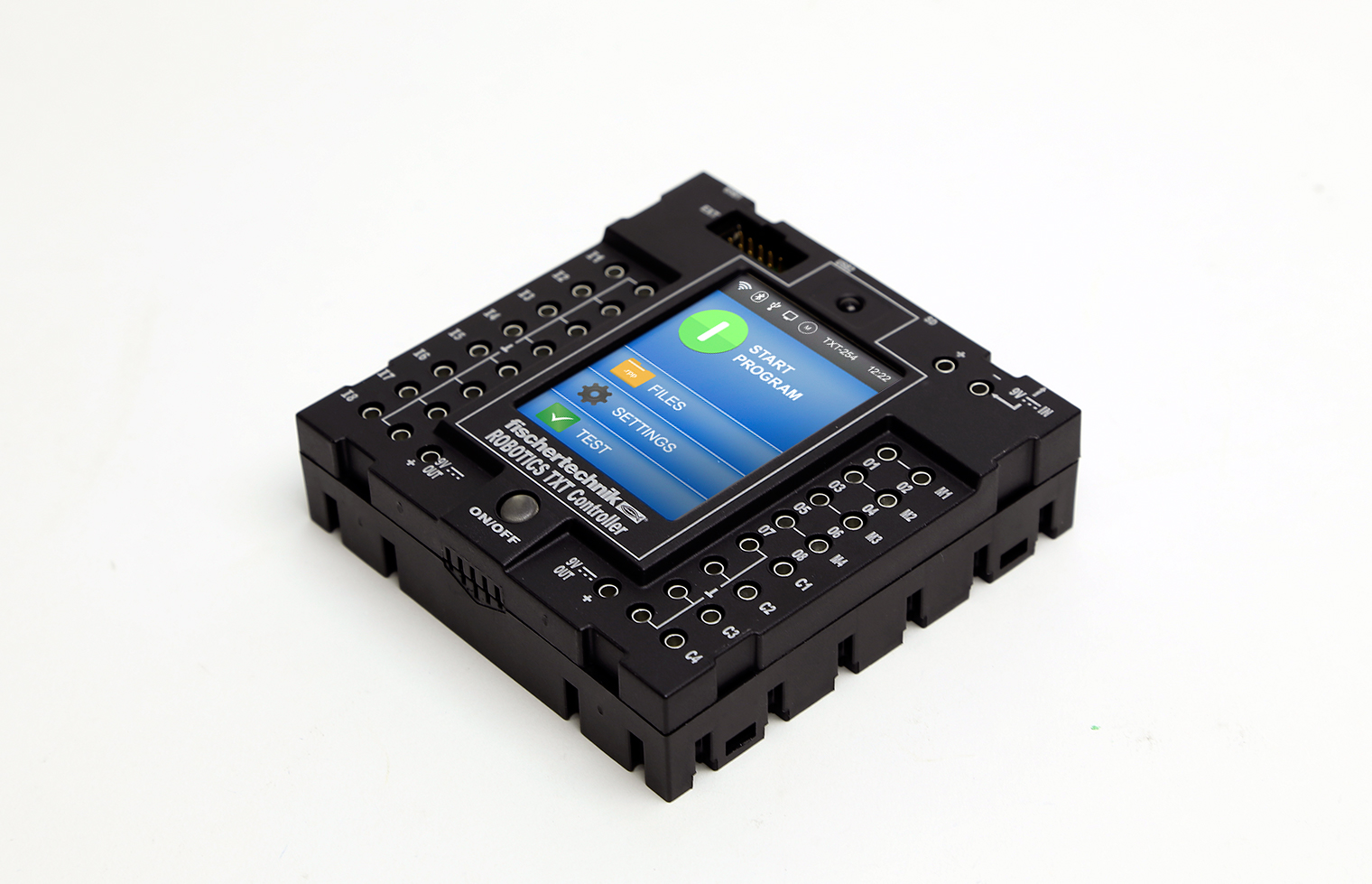
The TXT controller runs under the Linux kernel. If you wish, you can load your OS from a plug-in micro-SD memory card.
Memory
- 128 MB DDR3 RAM
- 64 MB FLASH
- Micro-sd
- USB mass storage device
Communications
The controller interface has the following interfaces:
- Bluetooth 2.1 EDR + 4.0
- WLAN 802.11 b / g / n
- USB-mini connector for computer connection
- USB-A connector with host controller function for connecting a USB camera, USB flash drive and other devices.
- IR photodetector for the remote control from the kit "Set for remote control"
- I2C interface
- UART interface
- CAN interface
Input Output
- Universal inputs: 8 pieces of digital / analog 0-9V or 0-5 kΩ
- Counting inputs: 4 pieces (0-9V Fin <1 kHz)
- Universal outputs (PWM 9V / 0.25A): 8 pieces
Just in case the inside of the TXT controller can be seen in the picture below:
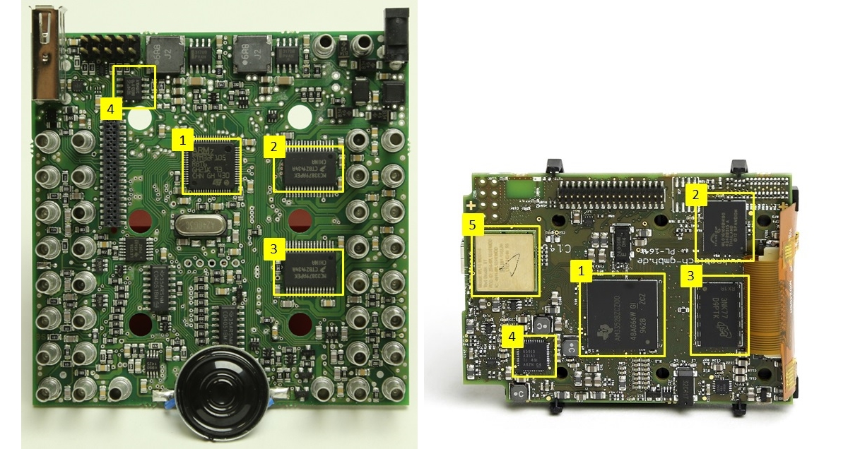
On the left PCB:
- ST STM32F105R8T6 - ARM Cortex-M3 Microcontroller.
- MC33879 - driver outputs.
- MC33879 - driver outputs.
- The TJA1040 is a CAN serial bus driver .
On the right PCB:
- TI AM3352B - ARM Cortex-A8 Microcontroller.
- Spansion ML01G100 - SLC NAND FLASH 64MB.
- Samsung K4B2G - DDR3L 1600 DRAM 128MB.
- TPS65910 - power management module.
- WL18MODGB (5) combined WiFi + Bluetooth module.
An important feature of this kit is the availability of hardware and software for experiments with computer vision. For this purpose, there is a video camera with a USB interface in the kit, and in the ROBO Pro tool software there is a library of computer vision functions and a configurator for setting and adjusting.
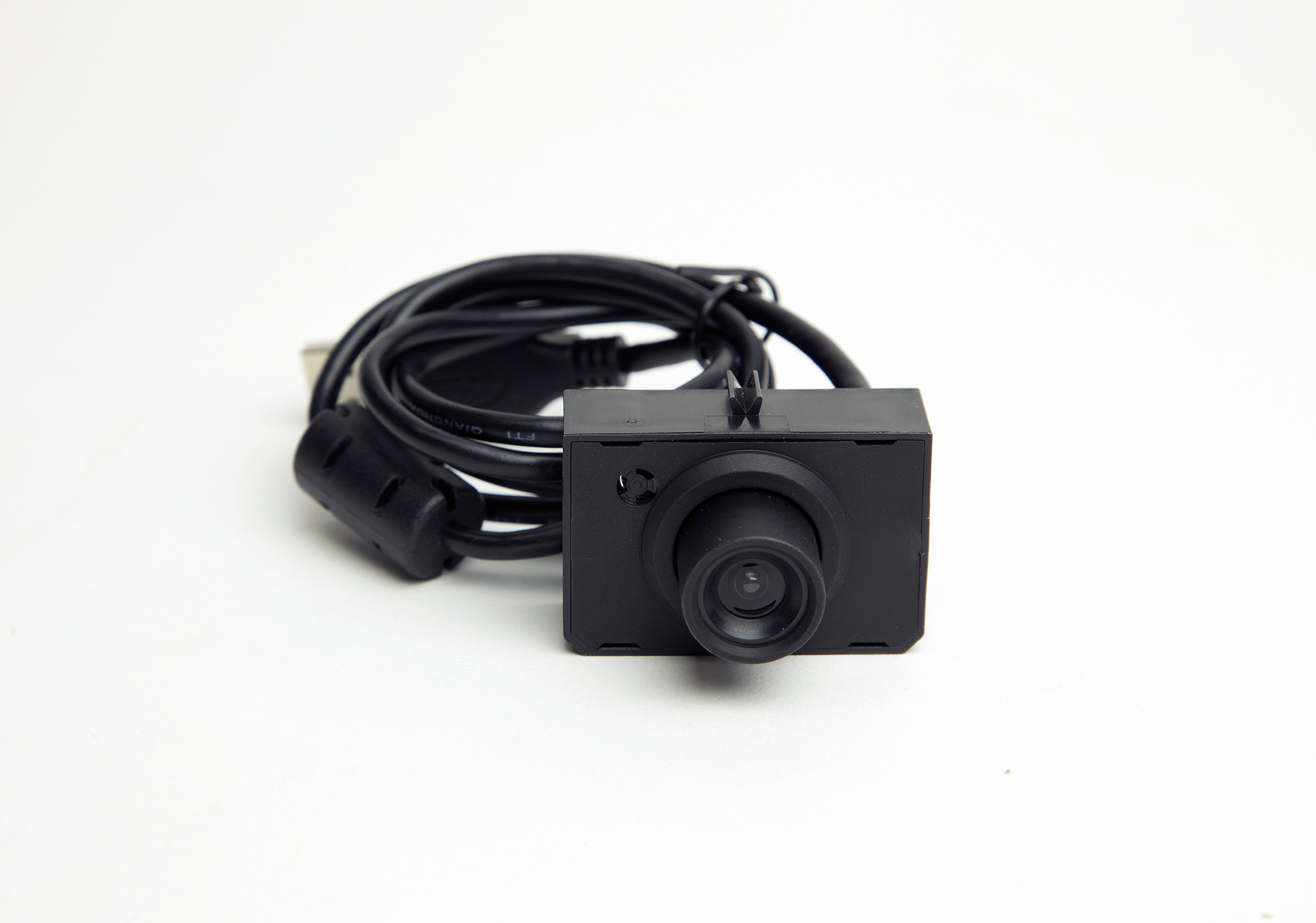
The library of computer vision contains the following basic functions for processing video frames:
- Calculation of the averaged brightness of a given video frame region.
- Search for a sequence of raster elements of the same color for a given region of a video frame.
- Search for geometric shapes, the calculation of coordinates and sizes.
- Motion detector in the video frame region.
Configurator of computer vision subsystem as part of ROBO Pro software:

ROBO Pro Tool Software
For the development of control programs for the TXT controller, it is proposed to use the ROBO Pro training tool software, which includes an algorithm flowchart editor, a library of basic software elements, a library of application functions, tools for commissioning and remote control. ROBO Pro software is included in the design kit. Separately buy it is not required.
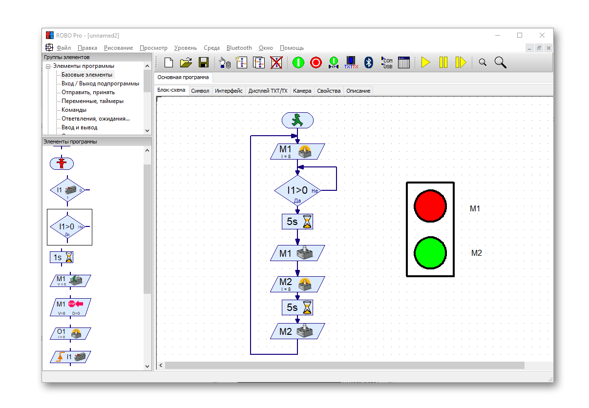
Usually the editor window looks like the image below:
The control algorithms are compiled in the form of ordinary classical flowcharts - as is customary in the specialized IT literature and technical documentation. Of course, you can reasonably ask me: - what about Scratch? Why is this in the documentation for ATMEL MK or SIMATIC PLC algorithms depicted in the form of block diagrams, and not in the form of scratch diagrams? Here I can hardly answer you reasonably. However, my internal engineer is delighted with the opportunity to use the generally accepted visual tool in a natural way for the first acquaintance of children with automatic control technologies.
Just in case the schemes of algorithms from technical documentation :

The flowcharts compiled in the editor can be launched for execution in two modes - locally on the tool machine or remotely by downloading to the target machine. The first method is convenient for debugging. during the execution of the algorithm, one can use step-by-step execution and highlighting of the current step of the algorithm.
For advanced users, ROBO Pro has support for multi-threaded algorithm execution. It also supports decomposition of algorithms into procedures and there are still user interface elements that can be placed directly on the sheets of flowcharts.
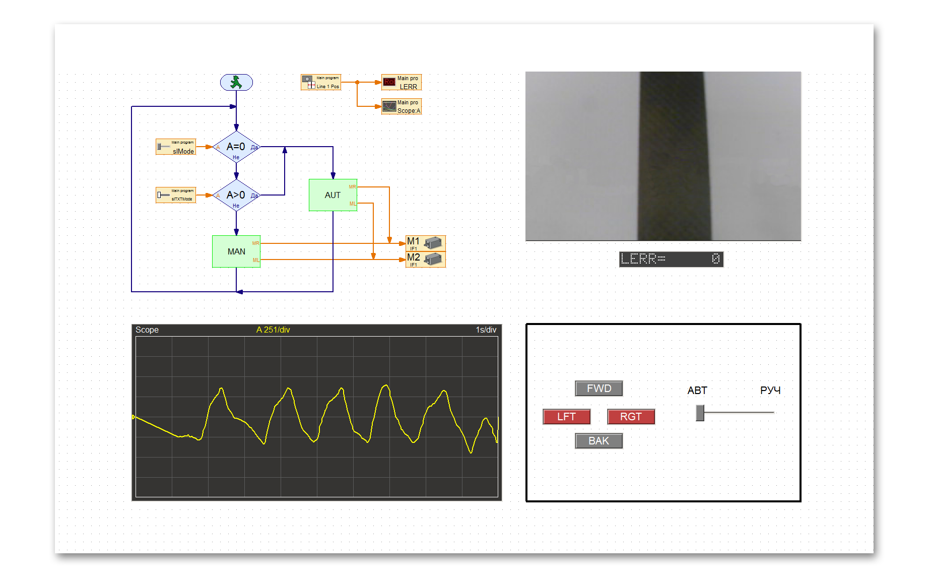
The library of user interface elements contains a recorder / oscilloscope, analog instruments and fields for input and output of digital values. This is a very important feature for both beginners and advanced users. The ability to record data in real time and the subsequent analysis greatly simplify the study of new control algorithms and significantly reduce setup time.
Here is the editor window with a more complex project:
Additional sets
The functionality of the 524328 set can be extended with additional sets from the ROBOTICS series:
They differ from designer 524328 in the absence of a TXT controller. It is assumed that the transition to these sets occurs after the solution of all tasks from the set 524328.
Project examples
I have prepared several clips that reveal some (but not all) of the features of the standard TXT Discovery set designer without additional details. All projects from examples lie on githaba . I will be glad to answer your questions in the comments.
Two simple algorithms for traffic lights:
Remote control using user interface elements and video streaming in ROBO Pro:
Automatic trolley control with feedback based on computer vision. The proportional law of regulation is used. The proportional gain KP = 3.5. It can be seen that the trolley moves along the route unstably - it swings and eventually moves off the track. Pay attention to the parameter recorder. It allows you to quantify the value of the overshoot after the movement is stopped:
The reason for the unstable behavior is that as the cart rotates, inertia forces arise that will continue to turn the cart, even if the control action from the proportional link is zero. As a result, we see how the cart slips through the line and then begins to turn in the opposite direction — oscillations arise in the dynamic system. This behavior greatly reduces the quality of control and in some cases can lead to failure.
To counteract the forces of inertia, a differentiating link was added to the structure of the regulator, which forms a signal proportional to the change in the error at the regulator input. Set the coefficient KD = 6.0 and see how the cart will behave:
Now the robot is steadily passing the track. Pay attention to the green signal on the recorder - this is the output signal of the differential link of the regulator, which helps to “slow down” the robot's turn when returning to the trajectory.
Conclusion
Above, I gave several examples of using the 524328 ROBOTICS TXT Discovery set for organizing practical exercises on the theory of automatic control. The examples given were very dry and devoid of theoretical calculations. I think that in one of the following publications I will be able to share my work on the organization of practical exercises in automation using the designers of fischertechnik. Would you find this interesting?
As usual, for lovers of engineering creativity who have mastered the entire post, a 15% discount on the code gktms1712 until December 31, 2017 inclusive in the Pakpak store. Glory to the robots!
Links
All Articles
