Features of programming microcontrollers via keyboard
The main purpose of the keyboard is typing. But it can also be used to write code to the microcontroller. The method is unconventional, but it can be useful when there is nothing else at hand. Or as entertainment with a keyboard that is no longer suitable for normal work. Below is about how to do it.
Approximate scheme of the programmer:
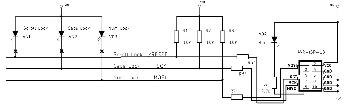
ScrollLock sets the level at the RESET input, CapsLock at the SCK input, NumLock at the MOSI input. The LED (VD4) at the MISO output is used to control entry to the programming mode. Items marked with an asterisk (*) are optional.
Programming Algorithm (for AT90 or ATmega microcontrollers):
1) Set 0 to SCK and MOSI (enable CapsLock and NumLock). SCK must be at 0 before RESET goes to 0.
2) Set 0 to RESET (enable ScrollLock).
3) Generate by changing the state of SCK and MOSI (ScrollLock and NumLock), the sequence of switching the controller to programming mode.
4) If the LED at the MISO output does not light up, it is necessary to form a single pulse on the SCK line and repeat the sequence (point 3).
If in 32 attempts the transition to the programming mode did not occur, it seems that something went wrong. If successful, further programming occurs through ScrollLock and NumLock (SCK and MOSI). Attentive and persistent boom can program the microcontroller manually.
Why is this not working?
The main problem with the implementation of such a programmer is the keyboard's own logic. Setting the state of the LEDs by an external program corresponds to the result in the keyboard, but the transition process of turning on / off the LEDs is her own business. Below are the waveforms of real switching:
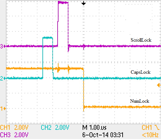
Enable NumLock (CapsLock and ScrollLock are included).
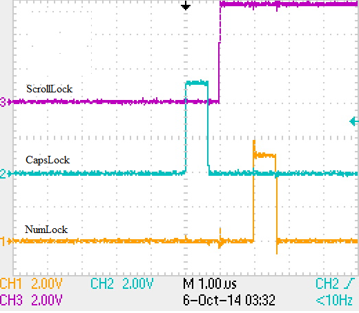
Turn off ScrollLock (CapsLock and NumLock are included).
It can be said that not all keyboards are equally useful for programming microcontrollers. Of the three that I had, only one of the LEDs switched independently.
What if you are so unlucky with the keyboard?
All the "transients" fit in time in a few microseconds, and the installation of a certain level on SCK, MOSI and RESET occurs with a delay of more than 1 ms. In this case, the signals for programming can be selected using a low pass filter. Here is an example filter:
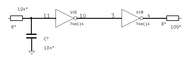
74HC14 - Schmitt trigger, it is intended for the formation of output levels. Can be replaced with an analog comparator (for example LM2901). In AVR microcontrollers, the inputs have an integrated Schmitt trigger, which makes it possible to get by with the RC chain if the output levels 1 and 0 correspond to the required ones.
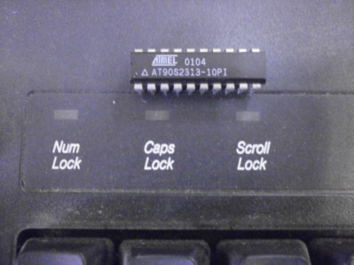
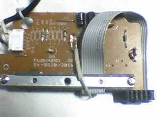
As an example. Keyboard that has become a programmer:
→ Software implementation of the programmer
All Articles