Simulator electric train ES1 "Swallow": the history of development, technology, results
Introduction
In our university, it was created, and not for the first decade the educational and laboratory complex "Virtual Railway" has been developing. The complex includes not only rolling stock simulators, but also simulators of workplaces for train dispatchers, station attendants, energy dispatchers, equipment simulators for diagnostics of the superstructure. If we talk specifically about rolling stock simulators, I note that the specificity of their development is somewhat different from the concept of a simulator for the driver. Railway University does not train drivers, our graduates are railway engineers. Therefore, the task of a locomotive or electric train simulator is not only to familiarize the student with the device of the cabin, controls, techniques and rules for managing rolling stock. The rolling stock simulator is also a simulator that reproduces the operation of the rolling stock systems in real time. When designing them, the main emphasis is placed on what processes take place in the equipment of the machine in different modes of its operation, and how these processes affect the controls.
Most recently, our team completed the development of the trainer speed electric trainer ES1 "Lastochka". About him and will be discussed further
1. The software part and the general structure of the training complex
What does it mean to create a railway training complex? This means developing a software / hardware system that includes
- Imitation of the driver's workplace - control panel with all the organs and means of displaying information;
- A computer complex that performs real-time simulation of the dynamics of train movement, the operation of its systems: power circuitry, traction drive, braking equipment;
- A device for interfacing control bodies, means for displaying information on the console and, if necessary, real train equipment included in the simulator with a computer model.
- Visualization of the view from the cab from the driver's workplace
- Training management subsystem with the possibility of visual presentation and analysis of data on the work of the train systems
As a result, all this resulted in a system whose structure is shown in the figure.
Functional diagram of the training complex electric train ES1
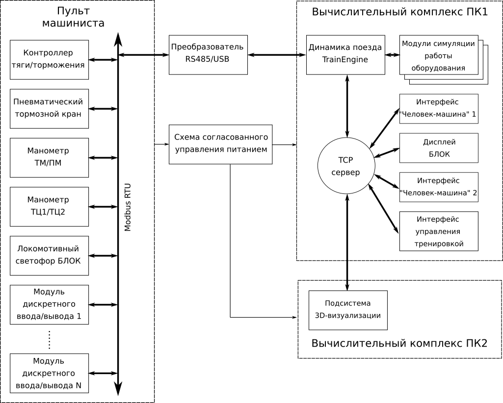
The computer complex of the simulator consists of two computers (PC1 and PC2) connected to the local network via a home router (TPLink 842 nd rev3, nothing extraordinary) with the possibility of remote access to the system via Wi-Fi.
GNU / Linux-based OS was chosen as the system platform for both machines. The reasons are as follows:
- Free license;
- The possibility of deep customization of the composition of system software;
- Orientation of the system for embedded solutions;
- Support for the core of all necessary peripherals "out of the box."
Despite the fact that household PCs are used in general, the application software in such a system should lead the user to a level of perception where he will not even guess that there is some kind of operating system inside. No keyboard! No mouse! Down with the desktop! He came in, turned off the power switch, waited a short time and got the system ready for operation. You can argue here for a very long time, but Linux, in the sense of the simplicity of implementing such an approach, bypasses other operating systems. Among the variegated variety of distributions, our choice was Arch Linux for the following reasons:
- The possibility of deep customization at the stage of system deployment;
- Rolling-release, which means fresh versions of packages;
- Binary packages, in contrast to the same Gentoo, which means high speed of deployment and maintenance of the system.
PC1 is the main one; it is operated by a computer model of a train, structurally represented by the TrainEngine train dynamics engine, which simulates the movement of the mechanical part of a train and modules that implement mathematical models of equipment not related to mechanics. These modules, together with the TCP server module and the Modbus RTU library, form a single executable module of the computing core.
TrainEngine implements the so-called generalized train model. Any train, whether it is a high-speed electric train or freight train, is mechanically a system of connected bodies, the movement of which is limited by the configuration of the superstructure. The moments provided by the traction subsystem and brakes are applied to the wheelsets of some bodies. So for any simulator the functionality will be the same. Therefore, the entire mechanics of the movement of the train is carried out in separate configurable libraries. The difference between the types of rolling stock is implemented at the level of software models of other equipment.
The interface between the driver and the modern locomotive / electric train today is saturated with display modules. In fact, many of the means of displaying information, implemented earlier by the switch instruments, have been reduced to a set of computer screens, to which current information is displayed. There are four such screens on the same “Swallow”: two multifunctional man-machine interfaces, a display of a safe locomotive complex (BLOCK) and a display of a video surveillance system.
Human-machine interface of a real electric train
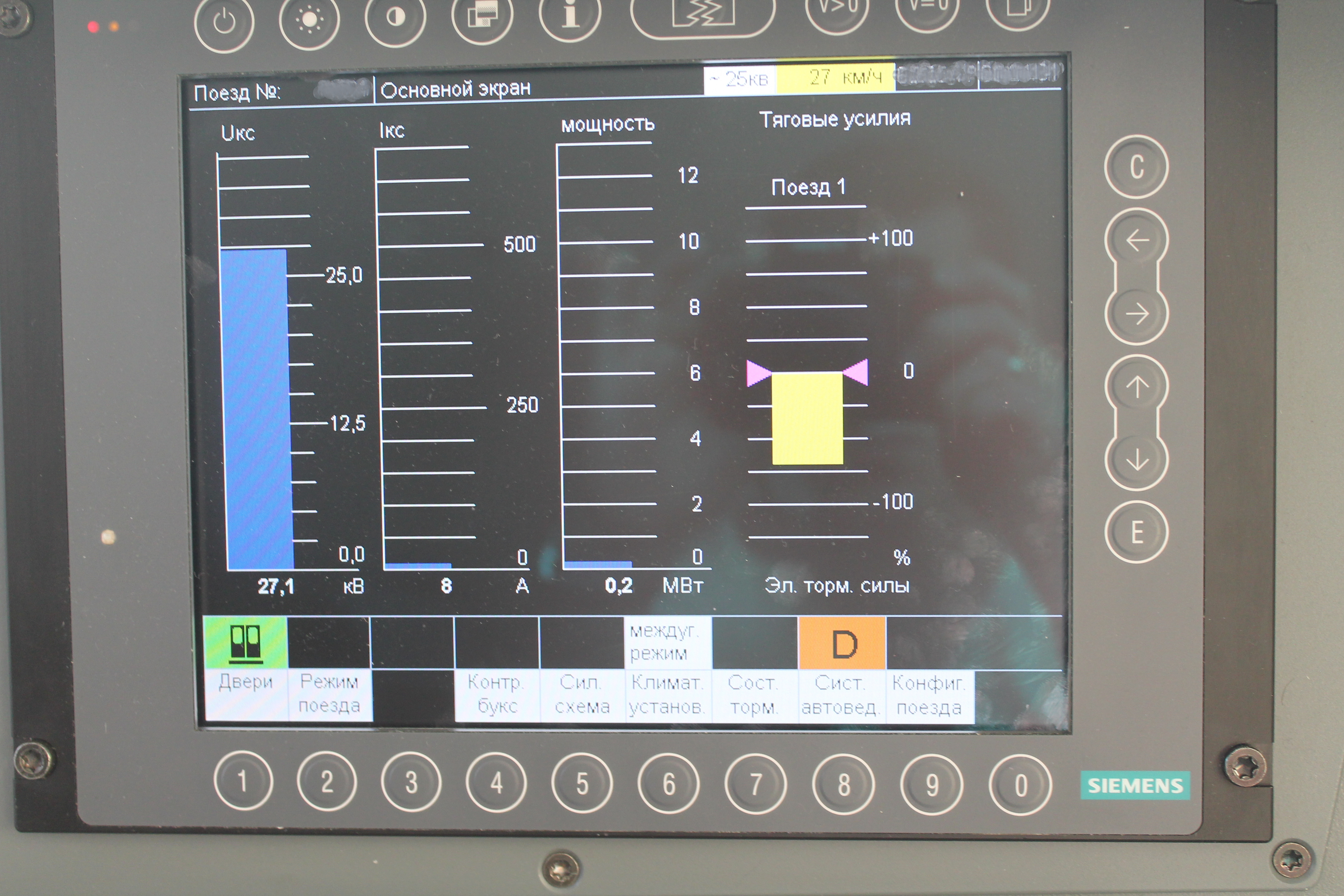
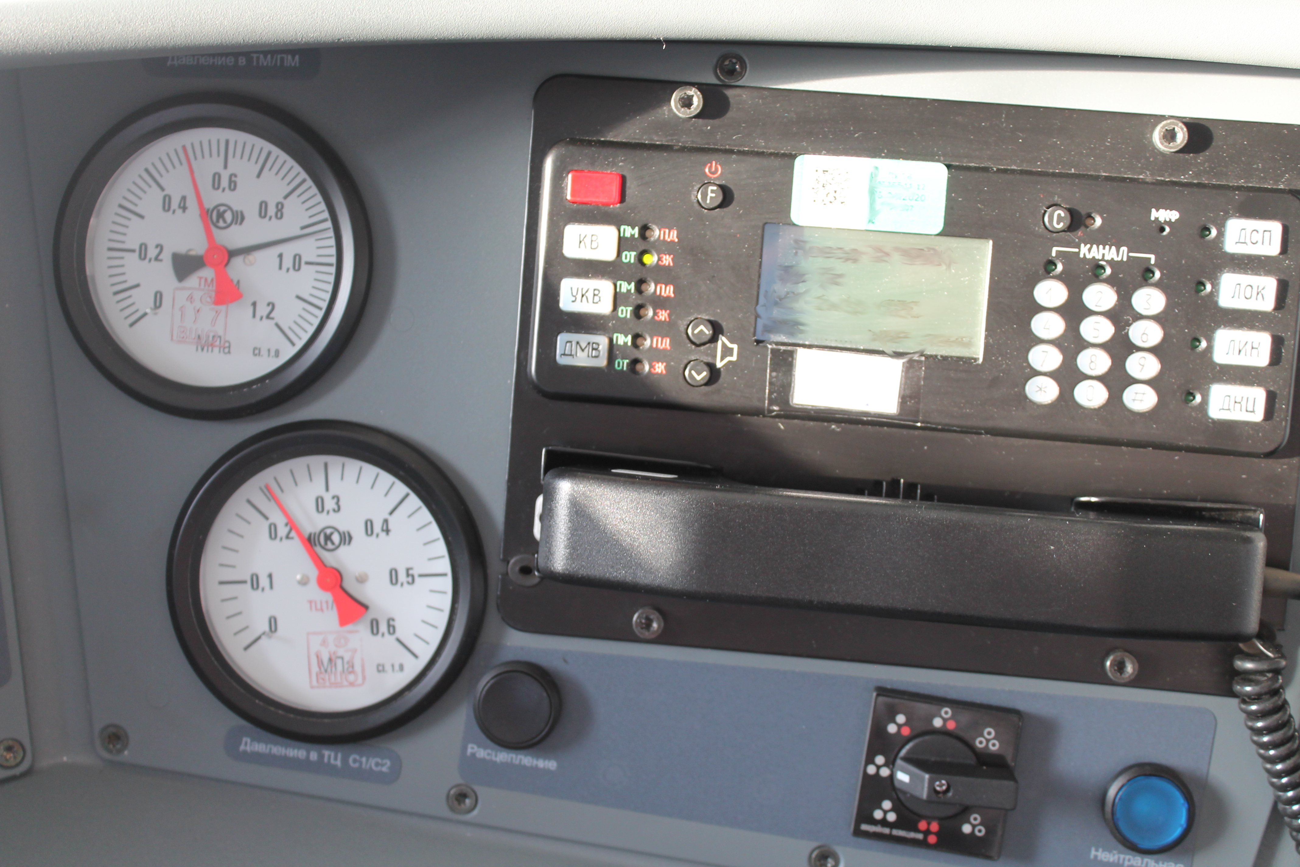
Safe Locomotive Complex Display (BLOCK)

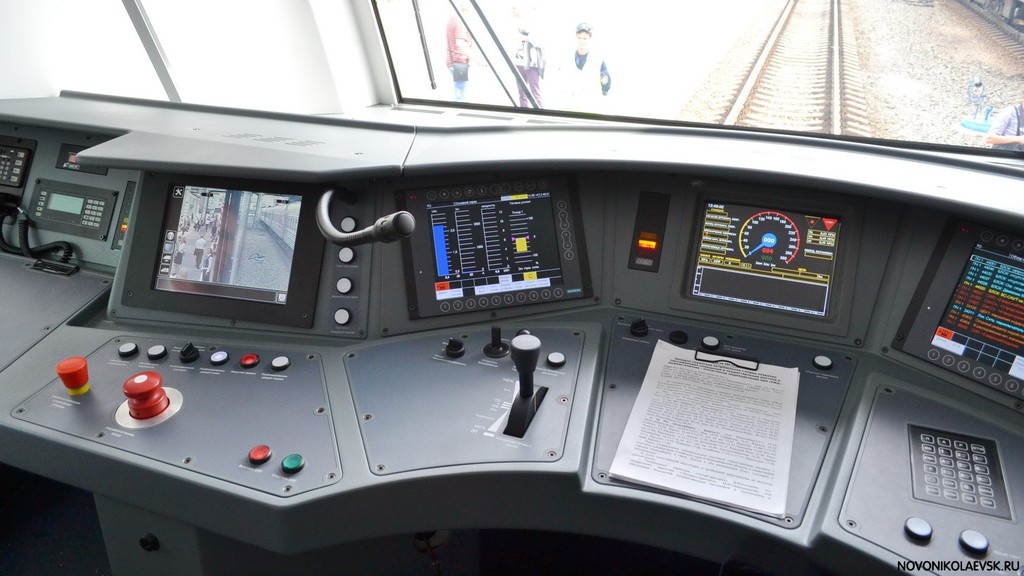
Cab interior and location of displays on a real electric train
On this electric train, each display module is a separate industrial computer that communicates with the control system using specific MVB / WTB protocols. These modules work under Windows XP Embedded (yes, imagine!).
In our case, such waste is meaningless - four touchscreens from the Elo company, connected to PC1 via Display Port and USB cables for the touch interface. Display modules are implemented as separate processes communicating with the computing core via TCP sockets. The Xorg setting allows each window to live exclusively in the monitor intended for it. Hardware buttons on the display frame are simulated by software.
It was possible to reproduce the basic functionality of these devices, concerning the electric train systems responsible for traction and braking. Applications are written in C ++ using the Qt5 framework. In general, Qt5 permeates all software, since it is highly adaptable to both creating user interfaces and having libraries to work with TCP / IP and Modbus RTU protocols. Plus, the famous “signal-slot” technology turned out to be absolutely indispensable for organizing the interaction of classes at all levels.
Man-machine interface of the simulator

Display BLOCK simulator

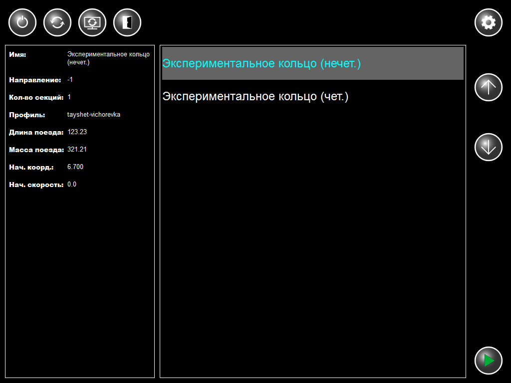
Due to the specificity of our simulator, the display of the video surveillance system was unnecessarily, instead, the remaining screen was used to meet our needs to control the launch of a workout, configure and manage computer power.
Workout Startup Interface
2. Hardware — Controls and Distributed Interfaces
The most difficult and expensive operation is equipping the simulator with controls authentic to the real cabin. About how to buy the original piece of iron does not appear for two reasons. The first is the enormous cost of the original units, justified by their use on real rolling stock and manufactured according to the corresponding requirements. The second is that mating with a computer is complicated by the fact that on real rolling stock, closed protocols of interaction between the equipment and the control system are used. The only way out for us was the independent design and manufacture of such elements as a traction / braking controller, brake valve and gauges of the brake system of the electric train.
To be clear, we are talking primarily about this lever
Real traction / braking controller in the electric train cabin
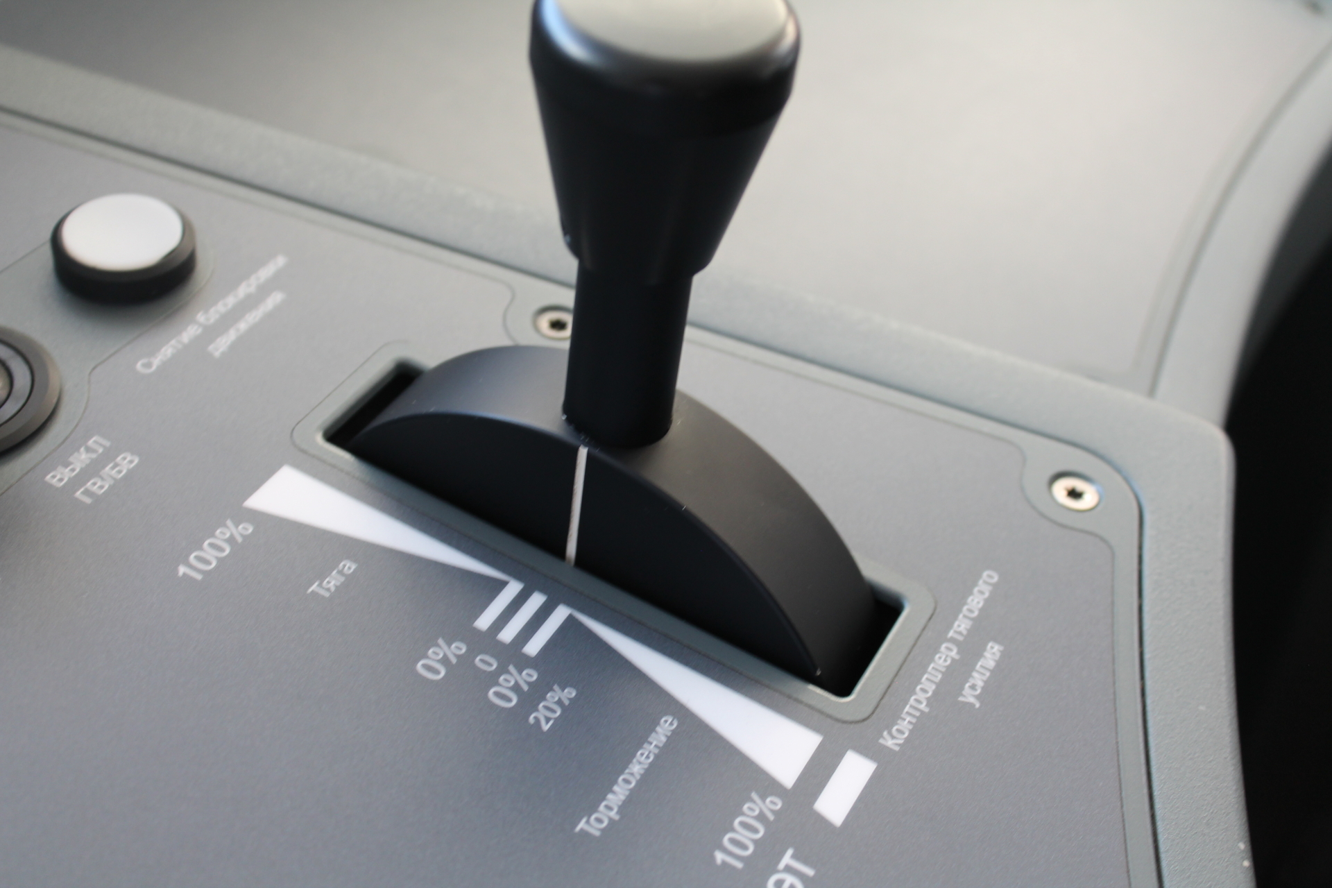
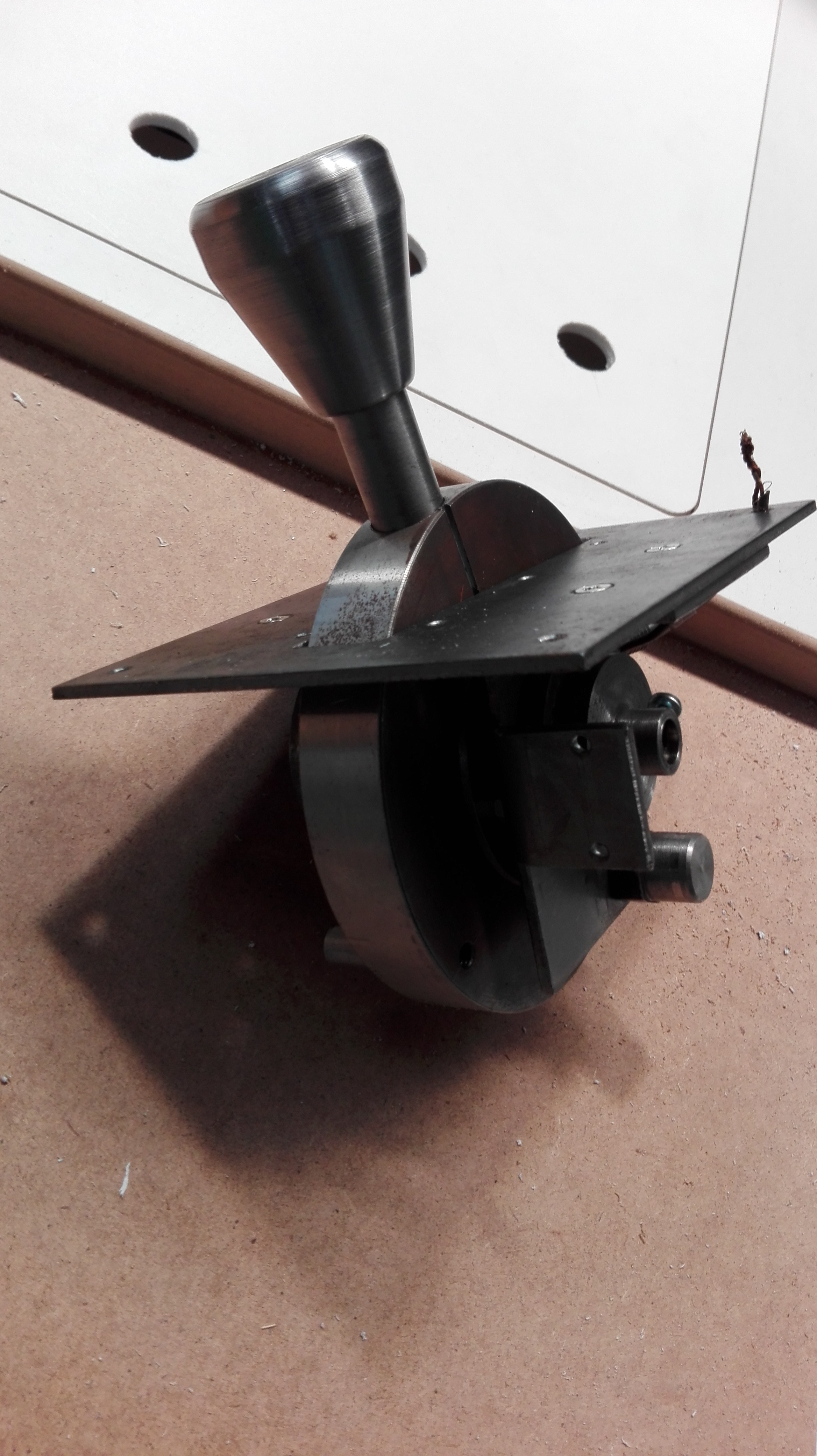
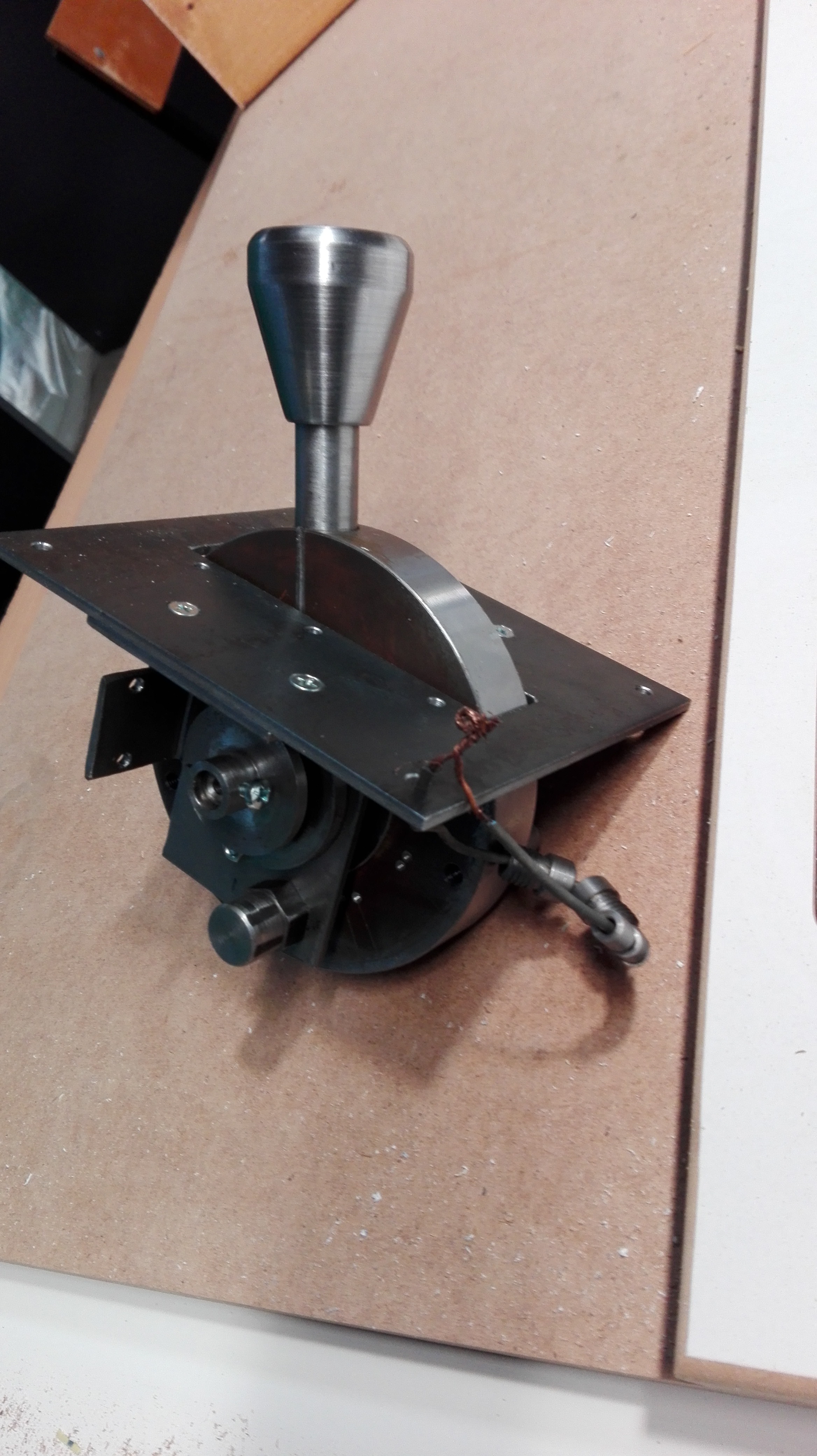
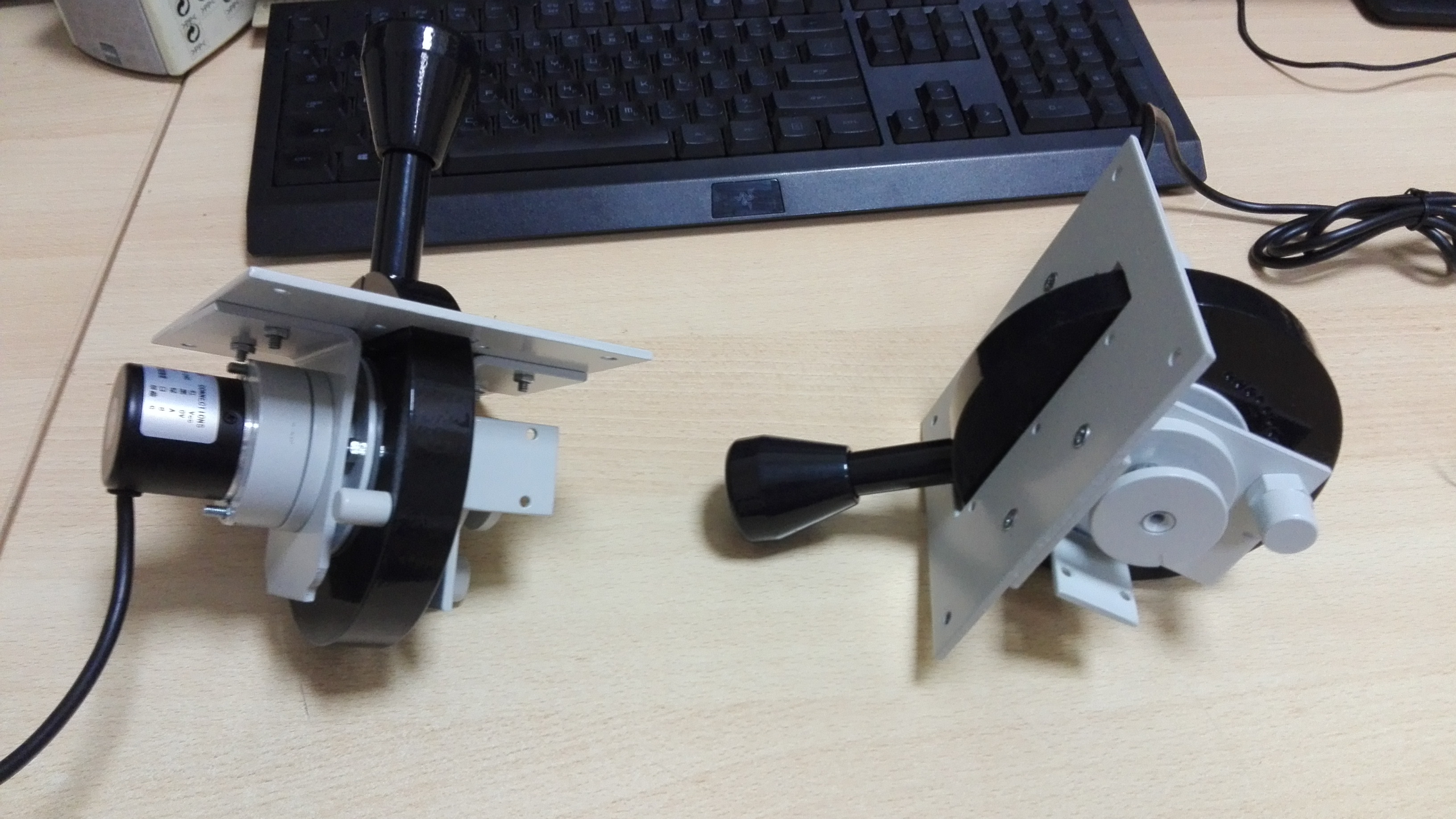
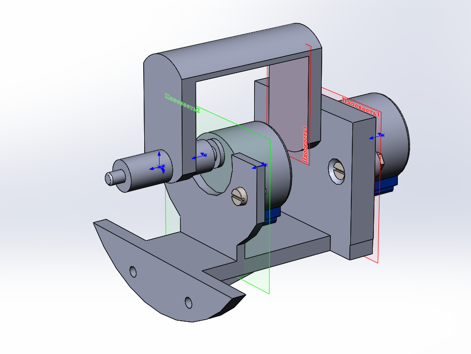
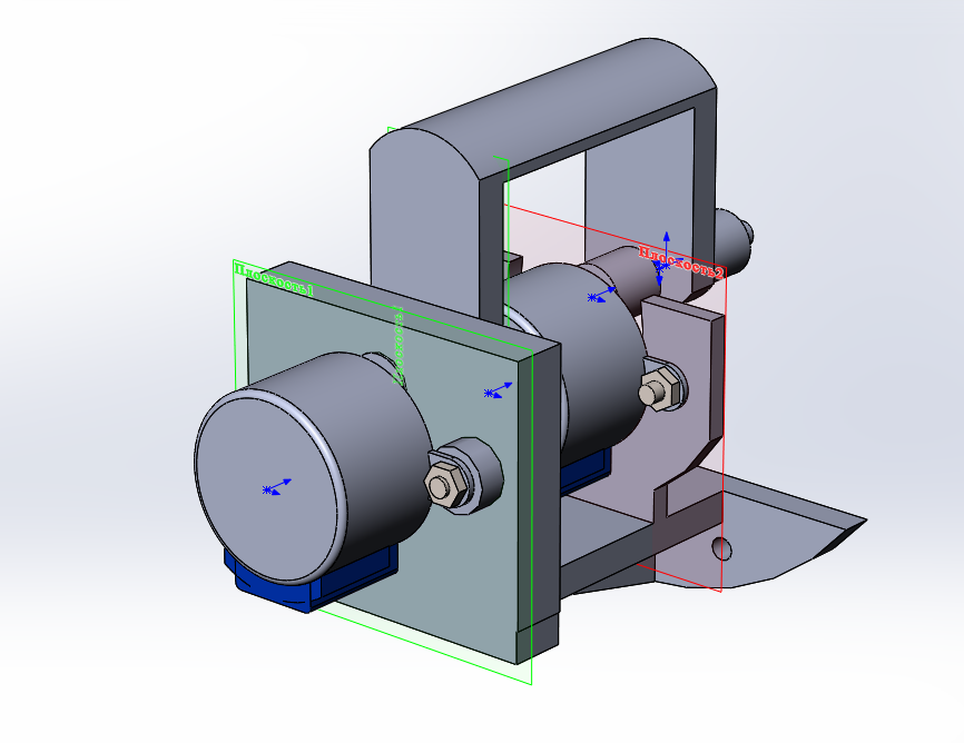
Its external dimensions, what sticks out above the panel, under the skeptical smiles of the locomotive brigade "Swallows", were able to measure with a stangel. We designed the insides in the way we thought was convenient in terms of assembling the unit in the future console and installing transducers on it. It turned out this concept, unified for both "joysticks"
The concept of a unified controller for the simulator

The pneumatic brake valve differs from the thrust controller only in the initial position of the handle at zero and in the presence of a plastic decorative lining. The rest of the controllers turned out to be unified in details, sensors and electronic boards.
Incremental encoders are used as position sensors, zero-position optical sensor is used to set zero in the control program. The firmware of the electronic part of the device interrogates the ecoder and the optocoupler and outputs the handle position as a percentage of thrust / braking force and a number of logical features: zero position, pressing the cap on the handle, emergency braking mode.
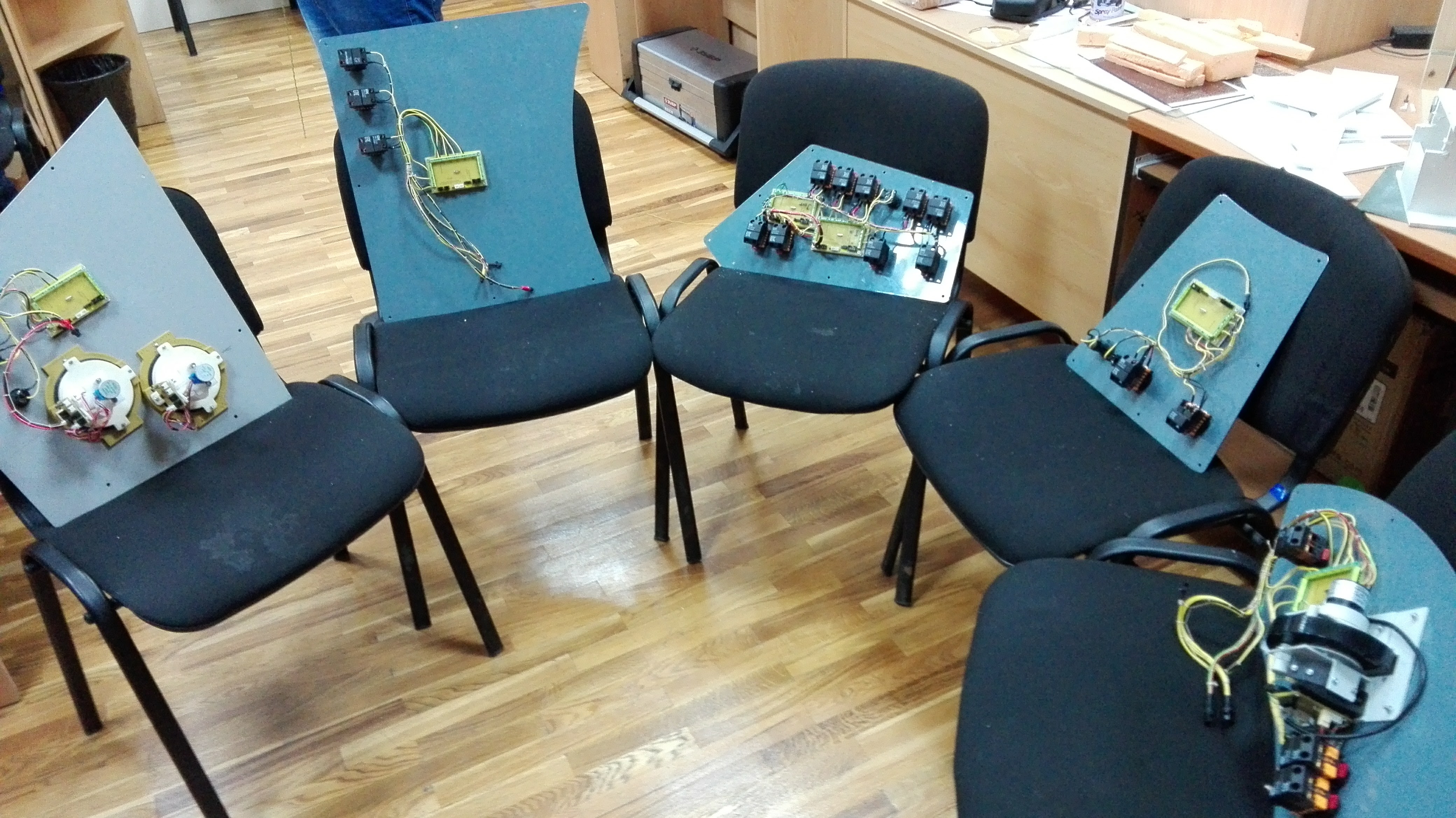
Under the spoiler there are a number of photos explaining in general terms the design of these devices.
Brief history of development in the form of photos
Mechanics in bare unpainted metal, just from the factory
Painted Draft Controller Kit

Mechanic controllers immediately after powder coating. Try on encoders
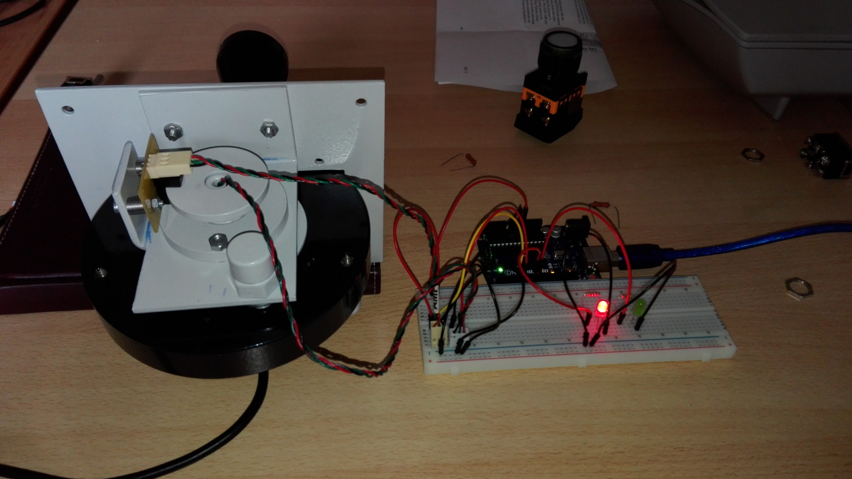
Subject on the debug stand
Pneumatic crane operator after installing the decorative lining, printed on a 3D-printer

Debugged traction controller assembly with "brains"

Traction controller installed on the standard panel. Visible adjacent discrete input / output module


Painted Draft Controller Kit
Mechanic controllers immediately after powder coating. Try on encoders
Subject on the debug stand
Pneumatic crane operator after installing the decorative lining, printed on a 3D-printer
Debugged traction controller assembly with "brains"
Traction controller installed on the standard panel. Visible adjacent discrete input / output module
Another stumbling block was the manometers, these
Electric manometer pneumatic gauges
Even if we had acquired regular - these devices are pneumatic, connected to the pipelines of the brake system. We needed a device that displays the pressure coming from the computer model. Plus it looks like the original. Plus, without being able to make gears, I had to contrive and invent a gearless mechanism that allows you to rotate the two arrows independently
Necessity on invention is cunning
Executive part of electromechanical pressure gauges
In the end, after a couple of months of thought, development, manufacturing and debugging, such an aggregate came out.
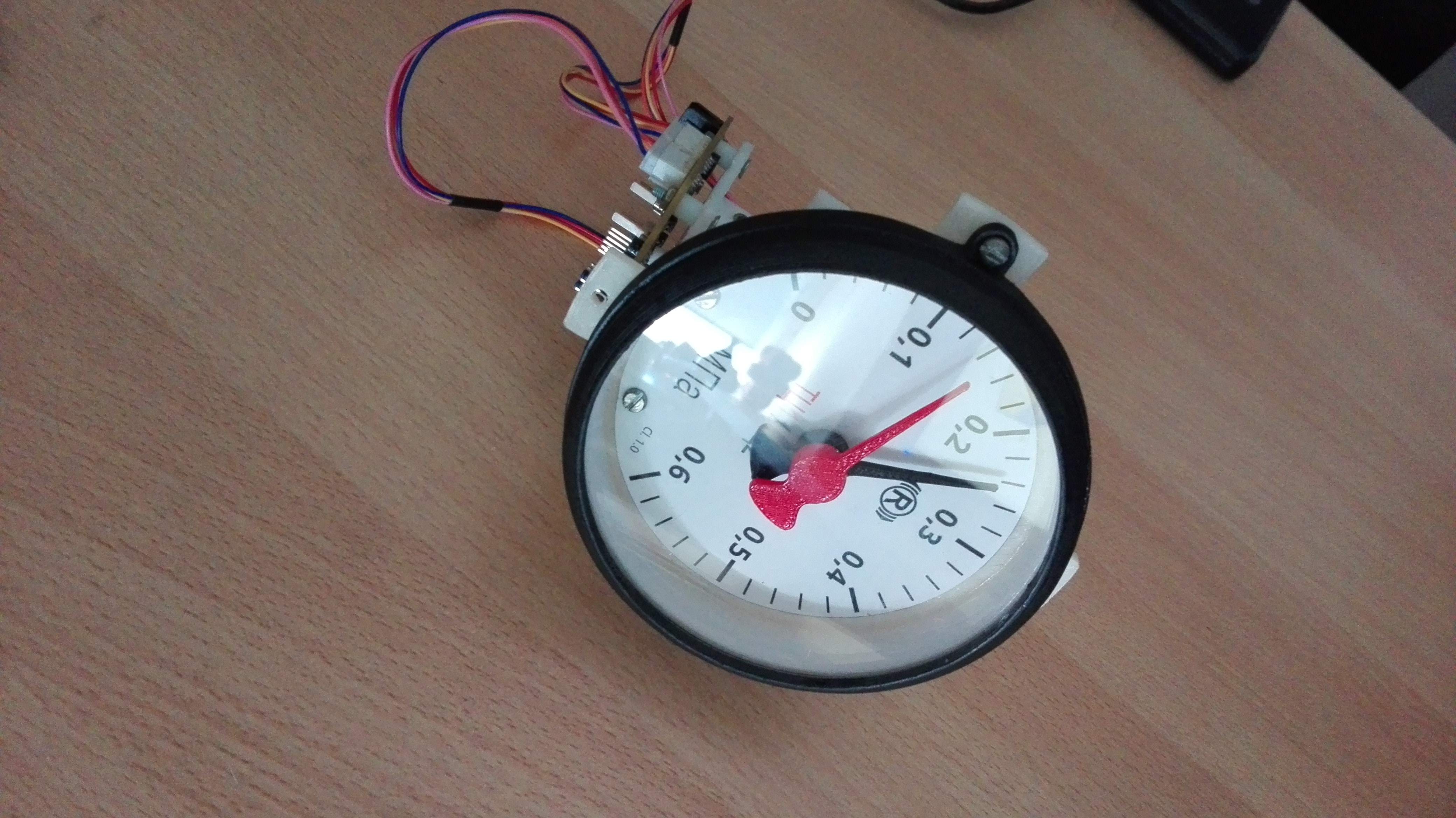
More photo gauge
Parts kit, made on a 3D printer
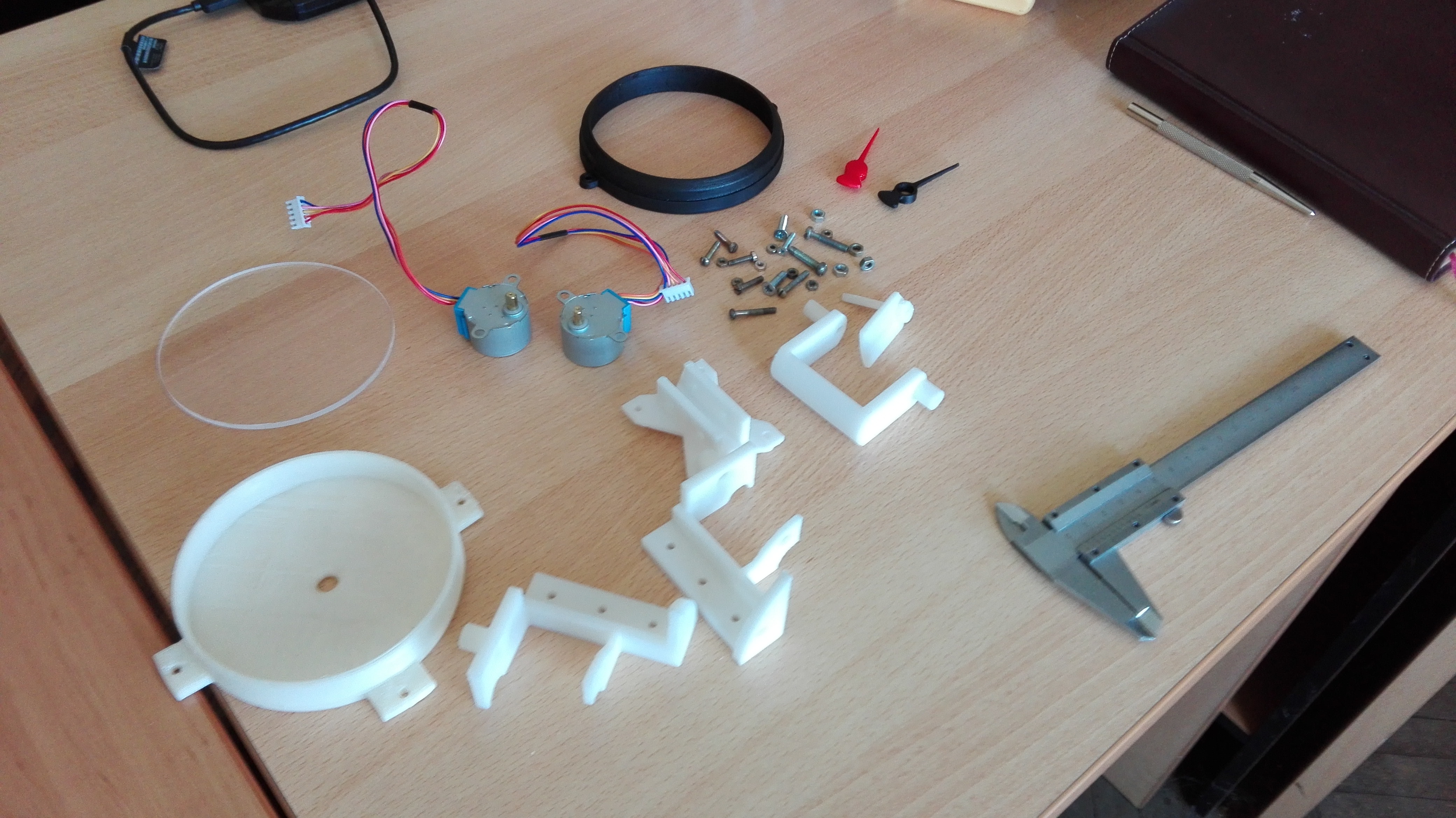
Debugging while writing firmware

Debugging while writing firmware
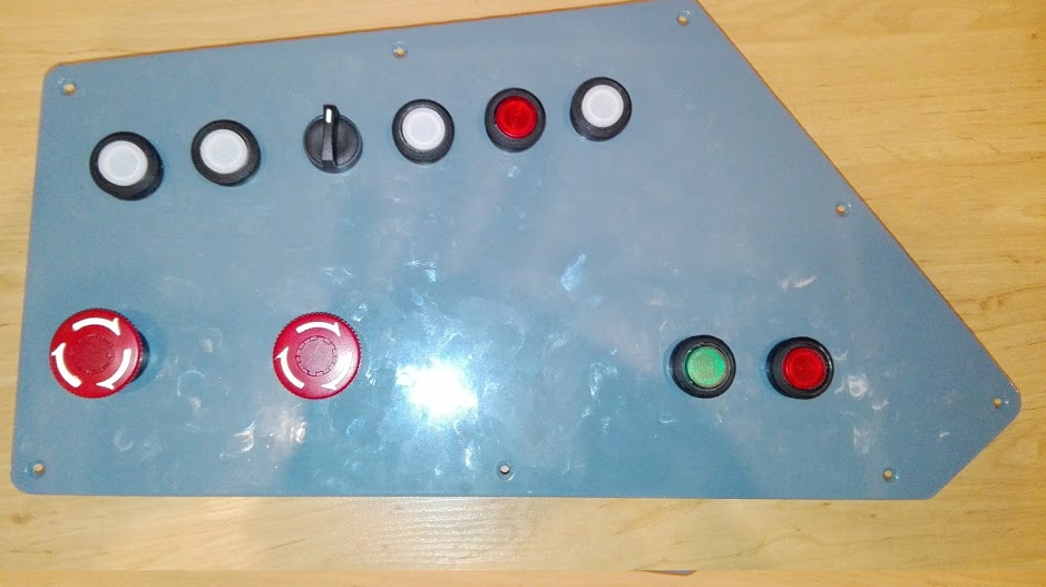
There were no problems with other controls - the rest is just buttons and switches. However, their number is quite enough to think about how to enter all these signals into a computer.
We decided to go beaten on an industrial scale by - RS485 is our everything. Short harnesses from buttons and warning lamps go to discrete I / O boards, and from there their state is entered into the machine via two twisted pair wiring.
The panel in zone J of the driver’s console top view
... bottom view of the installation. I / O boards visible
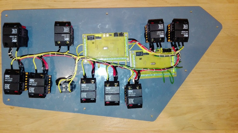
Modbus RTU was chosen as a data exchange protocol due to its simplicity, openness and prevalence in areas related to industrial automation. Discrete I / O cards are universal and are installed on the console panel at the place where they are needed. For such devices as controllers and pressure gauges, as well as locomotive traffic lights, due to the specifics of their work, separate solutions are used.
The result was a network of 12 subscribers. The signal is input into the computer complex via an RS485 / USB adapter. The software uses a ready-made implementation of Modbus RTU from the Qt5 framework.
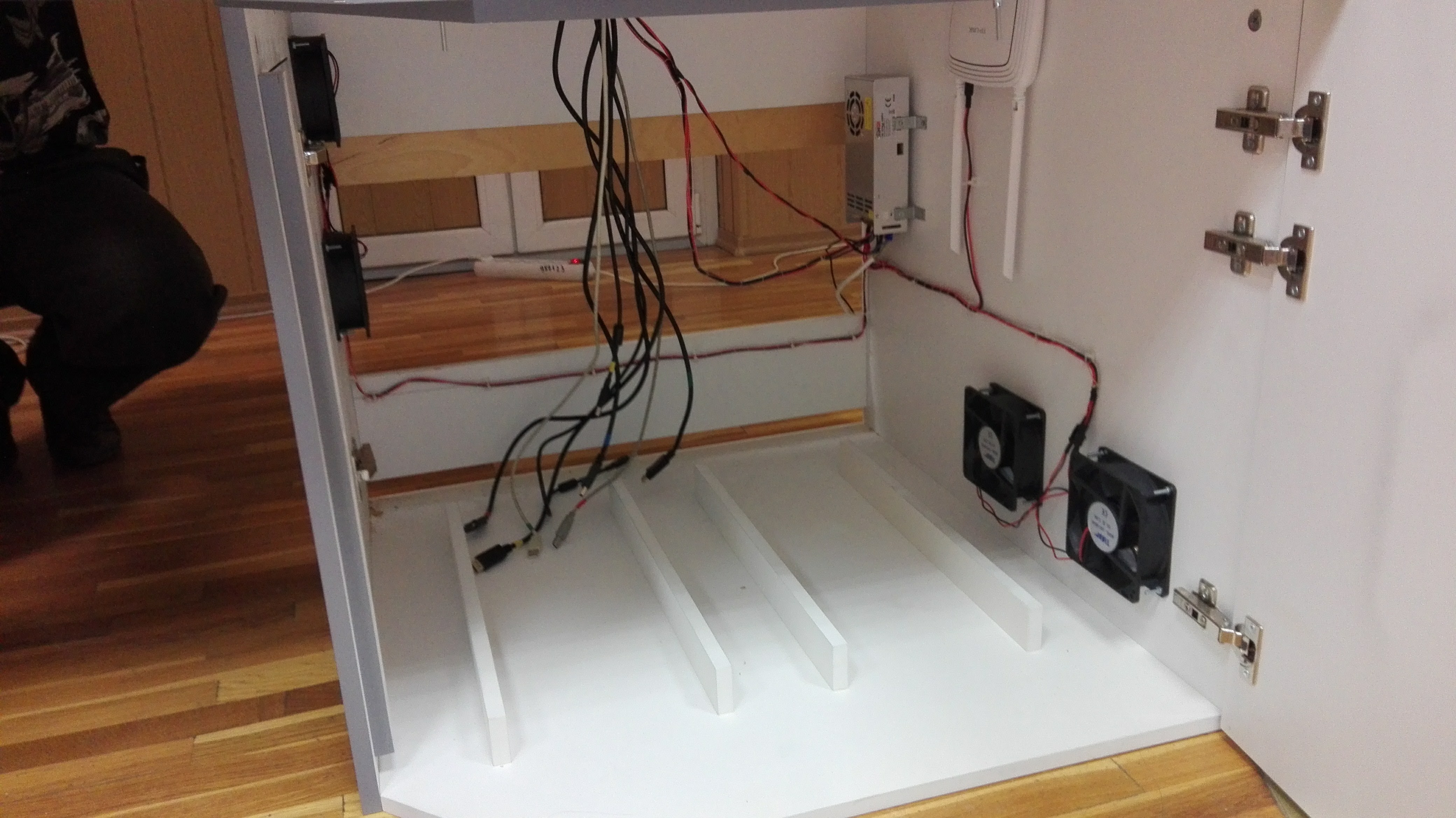
Offal console before the final assembly of the simulator
Some more photos
First launch of display modules on standard screens

Debugging is in full swing

Electrical compartment
Some of the stages of the final assembly

Assembled and debugged. Ready for installation in the cab

Debugging is in full swing
Electrical compartment
Some of the stages of the final assembly
Assembled and debugged. Ready for installation in the cab
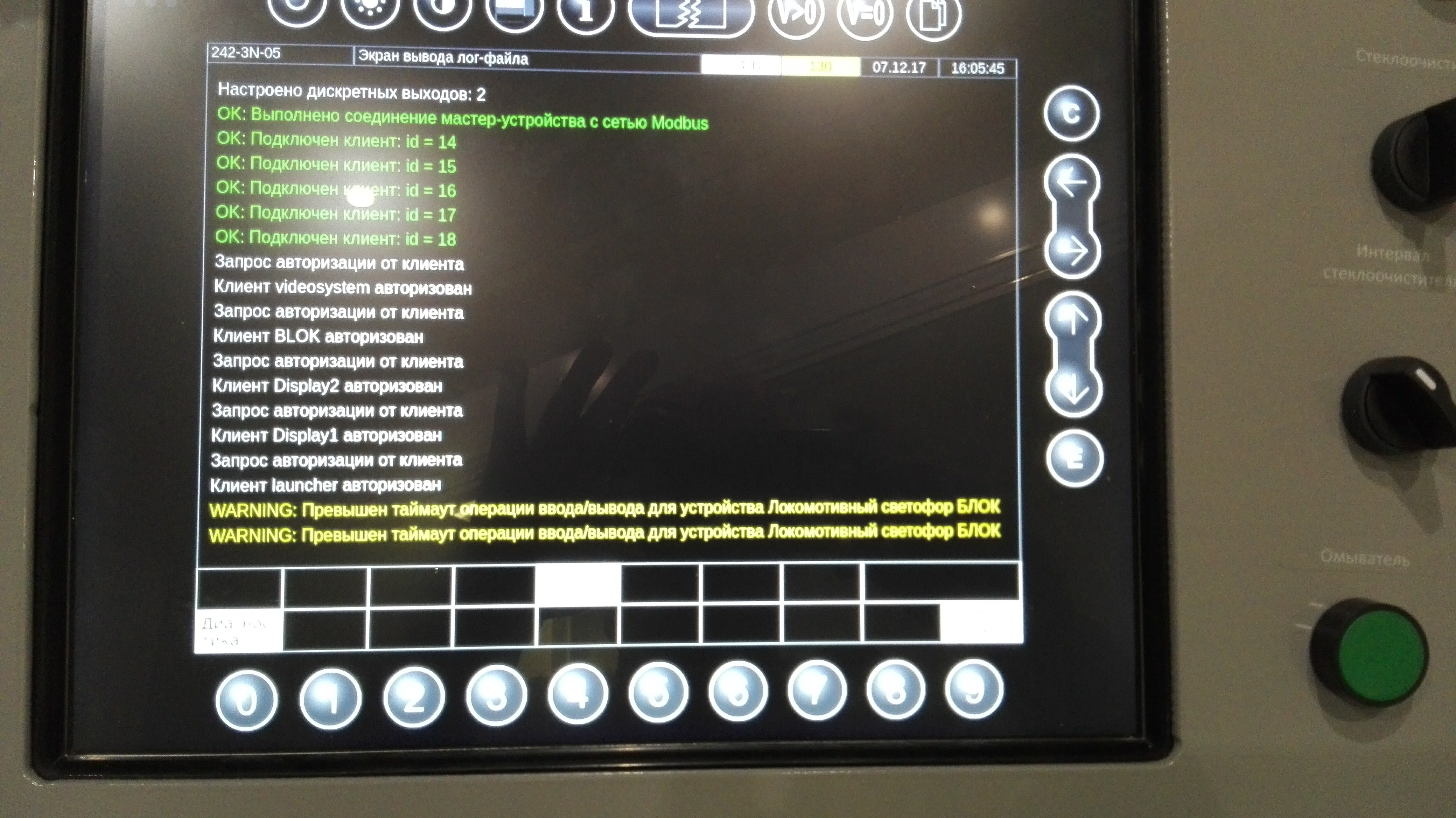
In general, it turned out quite reliably, and most importantly, convenient for the subsequent expansion of functions. All electronic components of the system are under the constant control of the software diagnostics system. Failure messages are issued as human-readable as possible, with an eye to the early detection of a failing unit.
Diagnostic screen with the log of the current session of the simulator
3. The subsystem of three-dimensional visualization
With all the power in terms of creating a presence effect, this part of the system is the least functional. Inside there is no "physics", all "physics" is server. The graphical client is delivered to a separate PC2 computer. From the server, he receives the so-called railway coordinate - moving along the path in kilometers, translates it into three-dimensional camera coordinates and shows the view from the cabin to the surrounding landscape. On PC2, the usual NVidia GTX 1060 is installed. The video system is written on Unity Personal.
Video system in the process of debugging

Here we still have a lot of work in terms of finding the optimal architecture, and we are constantly working on it. There are enough nuances here to make the story about them a topic for a separate post.
Conclusion
Currently, the simulator is undergoing trial operation and testing in the educational process in the laboratory of high-speed transport of our university. I hope I got an interesting story, thank you for reading for your attention. I apologize for the huge amount of heavy pictures, well, without this in any way.
() Center for Development of Innovative Competences of RSTU
All Articles