Session video transmission sound through the water with the exposure
“Lord almighty! It seems I have just killed Mr. May! ... But be that as it may, we will continue ”(C) J. Clarkson
In this article I will tell you how to transfer video (well, almost video) with the help of sound through water, using an ordinary laptop, a piece of wire, two 3.5 mm jacks and two piezo tweeters. And also I will explain why and how it works, I will tell a funny story about how we came up with it. And as a cherry on a cake, a draft on C # with source is attached to the article so that all who are interested can try it themselves, because scientific knowledge is verifiable, isn't it?
If suddenly the reader wants to dive a little deeper into the hydroacoustic theme, I suggest that you familiarize yourself with our previous publications, where we talk about our projects, revealing the difficulties of transmitting information through the water:
Underwater GPS from scratch for the year
Underwater GPS: continued
Navigation under water: pelenguy - not pelenguy, you are doomed to success
On the effect of cyanobacteria on the speech functions of the president
In general, you need to learn one simple truth: video through water at any significant distances (well, at least hundreds of meters) cannot be transmitted with the help of acoustics. The point is the extremely narrow available frequency band and the strong non-uniformity of attenuation of different frequencies with distance. A plus is noise, multipath propagation, reverberation, a change in the speed of sound in a medium from density (that is, from pressure, temperature and salinity), the Doppler effect, which by the way does not quite work as it does in radio communication.
Speed limits for the most advanced sonar modems are very far from being able to transmit video. As far as I know, the record belongs to the company EvoLogics and is 62.5 kbps with a stated maximum distance of 300 meters. Moreover, the words about the impossibility of transmitting video by sound through water (at reasonable distances) belong to Konstantin Georgievich, the founder and leader of EvoLogics.
When I was a research assistant at the Hydrosvyaz Research Institute, then absolutely stupid, I wanted great accomplishments,
Immersion in those memories causes conflicting feelings in me. Then it seemed that nothing and no one could stop us: we knocked out a Chinese milling machine for prototyping products from the director, assembled normo-pressure housings from Dutch water pipes Van De Lande, to whose manufacturer they even wrote a letter on the topic: “Didn’t you check Does external pressure withstand your pipes? ”. They collected mock-ups in breakfast containers at their own expense and secretly left the test house to collect tests, colleagues and relatives collected ice-drills, sledges, even bought a Chinese PVC boat in Auchan. Looking back, I feel like my heart is filled with horror, nostalgia and trembling.
In fairness it should be noted that all this time we received tremendous support from some of our leaders - in word and deed, and as a result all our crafts were legalized in OCD (meaning Experimental Design Work and not Obsessive Compulsive Disorder), which even presented at the International Navy Salon in 2013. Yes, we brought our water pipes painted by StDmitirev with our own hands into bright orange to the salon! Here they are, in suitcases:

Once, my friend and colleague, StDmitirev, in the midst of a conversation about spectra and spectrograms, uttered the following short phrase:
“But it would be cool to make such a system: a submariner sits in a submarine and looks at the monitor, on which the spectrogram smoothly moves, on which, like a finger ofanother submariner, letters and numbers are written on the misted window ofanother submarine”.
Everyone laughed, developed this theme, it seemed that they had painted a smiley on the spectrogram even on the same day and listened to how it sounds. I really wanted to bring this to a practical form.
Now it is difficult to remember (it was back in 2012). At my disposal was a working computer with a webcam, various antenna artifacts and a special “sonar bucket bucket” (VG-1-P) with water. They called him promoted because I showed every boss the work of various equipment mock-ups, which led to my promotion as a senior researcher.
I am not constrained by any obligations, the method itself has long been published in the public domain, and the results have been repeatedly reported at conferences.
So, I tell, how on spirit - how to transfer video through water:
How to generate a signal?
We remember that the idea is based on “drawing on the spectrogram,” that is, the transmitted image is the spectrogram of the signal. To transform a signal from the time domain into the frequency domain and back it is convenient to apply (well, for example) Fourier transform, more precisely, the fast Fourier transform, for brevity called FFT or, more commonly, FFT (Fast Fourier Transform).
Since we need to turn a picture (video frame) into a sound signal that could be emitted by a sound card of any computer, we will obviously use the inverse transformation, IFFT, for the formation. We will emit a picture in columns, and the signal for one column will be formed as in the following scheme:

=
Suppose that the FFT window size is N and there is an array of size N. If we consider its spectrum of the signal, then its zero element corresponds to zero frequency (constant), and the count with index N-1 corresponds to Sample Rate. It is necessary to choose the image frame size and FFT window size so that on the one hand it all somehow looks like video (transmission of one frame would take a reasonable time), and on the other, the frequency band used is adequate in principle and adequate to the available equipment . Now, if we add the brightness values of the image column (Frame coloumn) from any desired sample (from the bottom to the top of the diagram) and then perform the inverse FFT, then we will get a signal encoding one image column at the output. Now it remains for us to form signals for the remaining image columns in the same way and alternately emit them with a sound card.
It is worth noting that the FFT output gives an array of complex values, so our signal is the real part. Of course, the resulting signal in the columns is reduced to 16-bit signed integers (the digital sound signal is usually stored in this form) and normalized.
In fact, at the beginning of the picture I still enter several columns of maximum brightness, and later on the receiver side, this will allow us to determine the frequency response of the transmitting / receiving path (and the transmission channel), which, when inverted and slightly smoothed, will help us improve the received frame.
In my opinion, the easiest way to demonstrate the transmitter device is a piece of code, here it is (Encode method of the Encoder class):
public double[] Encode(Bitmap source) { Bitmap frame; if (source.PixelFormat != System.Drawing.Imaging.PixelFormat.Format8bppIndexed) frame = Grayscale.CommonAlgorithms.RMY.Apply(source); else frame = source; if (!frame.Size.Equals(frameSize)) frame = resizer.Apply(frame); double[] samples = new double[fftSize * frameSize.Width]; alglib.complex[] slice = new alglib.complex[fftSize]; double maxSlice; int sampleIndex = 0; int colsCount = frameSize.Width; int startRow = startLine; int endRow = startRow + frameSize.Height; for (int x = 0; x < colsCount; x++) { for (int y = startRow; y < endRow; y++) slice[y].x = (frame.GetPixel(x, frameSize.Height - (y - startRow) - 1).R / 255.0) * short.MaxValue; for (int y = 0; y < fftSize; y++) slice[y].x *= randomizerMask[y]; alglib.fftc1dinv(ref slice); maxSlice = double.MinValue; for (int y = 0; y < slice.Length; y++) if (Math.Abs(slice[y].x) > maxSlice) maxSlice = Math.Abs(slice[y].x); for (int i = 0; i < slice.Length; i++) { samples[sampleIndex] = (short)Math.Round(slice[i].x * short.MaxValue / maxSlice); sampleIndex++; } } return samples; }
The code, of course, does not pretend to anything and was written in a hurry purely for demonstration.
So what about the transfer speed?
And how to evaluate it? We managed (
For example, if the sampling frequency is 96 kHz, and the FFT window size is 512, we will send 120 x 120 pixels (8 bits per pixel) to the transmitter, then the time it takes to transmit one image frame is:
120 * 512/96000 = 0.64 seconds
Bit rate seems to be:
120x120 * 8 / 0.64 = 180,000 bits per second!
As I will show below, it is very easy to fall into such a delusion. What is wrong here? After all, everything is so simple and elegant!
In fact, such a calculation of speed is not applicable to this method, just as, for example, it is not applicable to an analog television signal, how many bits per pixel are there? =) And what about the simplest detector receiver? =))
The described method of transmission is essentially ANALOG and the concepts of “bit” and “pixel” are not applicable to it - in the same picture, theoretically, it’s not 8 bits per pixel brightness but 16 and “speed” will automatically increase twice.
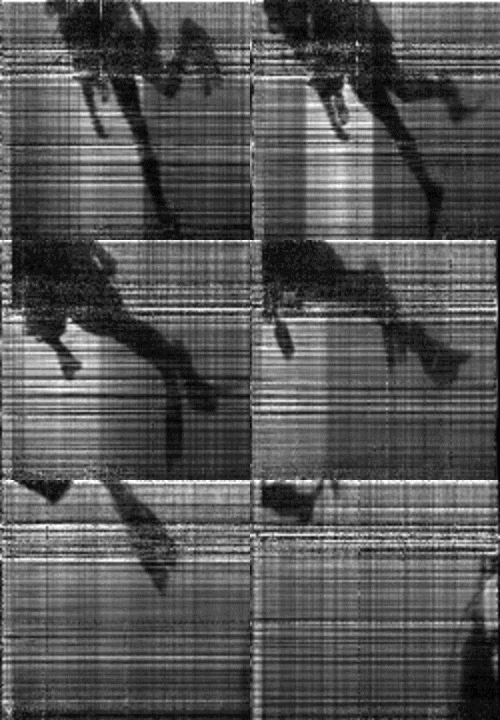
It's time to show the very first results of our "breakthrough":

The picture above was received by us in the winter of 2012 on the Pichuga River. The transmission distance was 700 meters. Yes, alas, my dear reader, this is not at all HD and does not even pull on the most disgraceful CamRip. I don’t remember who, but someone very accurately noticed that all our “videos” are like sending signals for help from a dying planet.
Remarkably, with a stretch this can be characterized as some kind of OFDM - data is transmitted on orthogonal subcarriers, which means good resistance to tonal and other narrowband interference - in this case, the individual "lines" of the picture are distorted. Impulse interference, on the contrary, distorts one or a group of columns. The characteristic "banding" of pictures is called the so-called. frequency selective fading due to multipath propagation, but I will talk about this some other time.
How does the receiver?
At once I will make a reservation that in order to try this method in a bucket or even in a small pool, two watch pieces (such round ones) with a sound card socket soldered to them will be quite enough. For the transmitter, you can take a rather long (2-3-4-5 meters) and unshielded cable, having sealed the piezoelectric varnishing element itself or with a small layer of sealant - just enough for several times. The resulting sonar antenna (no, but what?) Is inserted into the headphone jack.
In the photo below are different piezos that are at hand at the time of this writing. All piezoelectric elements shown are quite suitable for “try” and are usually found in any

For the receiver, it is better to take a shielded microphone cable with the same connector and a piezo plastered with sealant or varnish at the end. This antenna is inserted into the microphone jack.
For experiments on a reservoir, it is better to take some piezo ring as a transmitter and feed it to an amplified (an amplifier with a properly wound transformer enough for a few hundred meters in a good reservoir
So, back to the receiver, more precisely to its software part
The most important thing in communication is synchronization and the determination of the presence of a useful signal. In our example, detection is performed on the energy in the band: the places where it rises sharply (the beginning of the frame) and where it drops sharply (the end of the frame) are determined, with the condition that from the front to the fall should be no less than the frame duration.
For all its simplicity, it works surprisingly well.
Data from the sound card is collected using FFTSize samples, FFT is immediately performed on them, and they are stored as separate “slices”, waiting for the moment when the search procedure is processed, here is its code (Search method in the Receiver class):
private void Search() { int sliceIndex = 0; int frameWidth = encoder.FrameSize.Width; int minSlicesToSearch = Convert.ToInt32((frameWidth + 5) * 2); int sliceSize = encoder.FFTSize; double weight; int lastRisePosition = 0; int prevRisePosition = 0; while ((slices.Count > minSlicesToSearch) && (sliceIndex < slices.Count)) { weight = 0.0; for (int i = 0; i < sliceSize; i++) weight += Math.Abs(slices[sliceIndex][i]); double ratio = weight / previousWeight; if ((ratio >= risePeekRatio) && (sliceIndex - prevRisePosition > frameWidth)) { prevRisePosition = lastRisePosition; lastRisePosition = sliceIndex; if (lastRisePosition + (frameWidth + 5) < slices.Count) { double[][] samples = new double[frameWidth + 5][]; for (int i = 0; i < frameWidth + 5; i++) { samples[i] = new double[sliceSize]; Array.Copy(slices[lastRisePosition + i], samples[i], sliceSize); } slices.RemoveRange(0, sliceIndex); lastRisePosition = 0; if (FrameReceived != null) FrameReceived(this, new FrameReceivedEventArgs(encoder.DecodeEx(samples, 5))); lastRisePosition = sliceIndex; } } sliceIndex++; previousWeight = weight; } Interlocked.Decrement(ref isSearching); }
And here is a piece of code that is responsible for decoding the image (Encoder.DecodeEx):
public Bitmap Decode(double[] samples, int measureCols) { int colCount = samples.Length / fftSize; if (colCount == frameSize.Width + measureCols) { int rowCount = frameSize.Height; Bitmap temp = new Bitmap(colCount, rowCount); double[] slice = new double[fftSize]; alglib.complex[] sliceC = new alglib.complex[fftSize]; int samplesCount = 0; byte component; int decodeStart = startLine; int decodeEnd = startLine + rowCount; double maxSlice; for (int x = 0; x < colCount; x++) { for (int y = 0; y < fftSize; y++) { slice[y] = samples[samplesCount]; samplesCount++; } alglib.fftr1d(slice, out sliceC); maxSlice = double.MinValue; for (int y = decodeStart; y < decodeEnd; y++) if (alglib.math.abscomplex(sliceC[y].x) > maxSlice) maxSlice = alglib.math.abscomplex(sliceC[y].x); int offset = temp.Height + decodeStart - 1; for (int y = decodeStart; y < decodeEnd; y++) { component = (byte)(255.0 * alglib.math.abscomplex(sliceC[y].x) / maxSlice); temp.SetPixel(x, offset - y, Color.FromArgb(component, component, component)); } } return temp; } else { throw new ApplicationException("Specified array length error"); } }
And now I propose to look at the results of experiments on the transfer of "video", conducted at different times in different reservoirs.
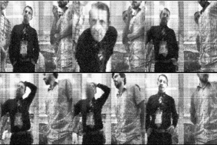
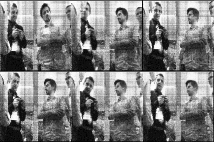
Both pictures (below) were recorded at the international naval salon in St. Petersburg in 2013 on our (then) stand through two laptops and an aquarium.
Disassemble what is written on the badge is not possible


But the two "videos" recorded by us in one of the bays of Lake Ladoga in Karelia, they are a kind of record for this method (we just never tried and we will hardly be farther) - the first one was received at a distance of 500 and the second is 1000 meters :
Video transmission over water, 500 m distance (8.7 mb file)

Since the “video” was written in real time using a webcam, various strange things fell into the frame. It will be very interesting if someone guesses and writes in the commentary what is in the background in the last “video”).
In confirmation of the fact that the method has long been published - our article is already for 2013
To capture images from a webcam, I used the wonderful AForge library.
The functions of working with complex numbers and FFT are used from the excellent AlgLib library.
And, as I promised, the whole project in C # (VS2012) is attached to the article as a material for "home" work. For convenience, there is a separate project and binary files .
The demo provides the ability to change (move) the occupied frequency band as well as gamma correction of the output frame (everything can be changed in real time).
PS
I have not taken C # in my hands for a long time and it is very difficult to find time in the work schedule, so I apologize in advance for the confusion and haste of the code.
Pps
A piece of wire, two jacks and two piezos are not attached to the article - not enough for everyone.
Errata and Appendix
- In some sound cards at the input there is a low-pass filter which tragically cuts everything above ~ 15 kHz (why ???).
- By default, the demo project works with a sampling rate of 96 kHz, but not all modern sound cards support it (Why ???). If the equipment cannot 96 kHz, then it needs to be set in the settings of 48 kHz, if not, then 44100 is certainly supported everywhere, however, the duration of transmission of one frame will be correspondingly longer.
Here is a list of laptops and sound cards that can be considered as equipment for a young sonar:
- Lenovo ideapad Y510P with JBL sound
- Asus n55s
- Asus k501u
- Sound Blaster X-Fi Surround 5.1 external sound card (model no. SB 1095)
All Articles