Russification of the LiquidCrystal_I2C library for Winstar OLED displays
For Winstar line displays, it is very tempting to reduce the number of control connections, which even with a four-wire power supply produces at least six (you can not connect R / W, see this publication of the author ). They say (including Winstar themselves, see the official site ) that the WS0010 controller can be controlled by SPI (and some even by I2C !), But they do not put instructions in the documentation on this topic, and how to manage it unclear. In addition, SPI does not help much - instead of six connections, we get four attached to the display, because even for some purposes SPI is rarely used in amateur practice. Therefore, the most convenient solution in terms of reducing the number of connections for standard Arduino boards is to use the so-called expander of I2C-based ports called PCF8574 . This reduces the number of necessary connections to two (not counting the power), and based on the findings of the standard TWI port, which does not interfere with connecting to it various sensors, clocks, etc.
In fact, the PCF8574 chip can be adapted to a large number of very different uses (read buttons, light up LEDs, etc.). In the write mode, the microcircuit directly translates the value of the bits in the byte transmitted on the I2C bus to the state of eight outputs (while reading, on the contrary, the state of eight lines is transmitted to the transmitted byte). The I2C address in PCF8574 can be changed by setting the level on the three inputs of the address assignment, so that using one bus you can set or read up to 64 lines using two wires. In this case, there are some peculiarities due to the asymmetry of the “0” and “1” states of the pins of the parallel port PCF8574, both when working at the input and at the output (see here ), but our task is to control the LCD or OLED displays on the I2C bus, they will not interfere.
There is even no need to dilute the adapter board for the displays yourself. Especially for the management of HD44780-compatible displays, numerous varieties of adapter modules are available (see photo). Along one edge they have a single-row PLS-type pin connector, the wiring of which allows you to directly connect such a module with an LCD or OLED display.
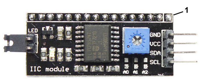
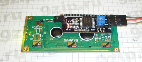
If the module is oriented so that the output of module number 1 (read from the input connector, see photo above) coincides with output 1 of the display, the adapter card can be installed directly on the display board as shown in the photo below (photo with site 9zip.ru). In this case, of course, the pitch of the pins and the type of the connector itself must match. Therefore, among the common Winstar lowercase OLED displays, as in the picture, only WEH1602A and 2004A types can be connected, for type 1602B the module will have to be rotated 180, and for people who are loved by 2002A / B and 1202/1204 to make adapter cables.
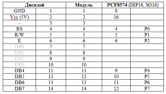
The pinout for the OLED display is shown in the table. If you want to connect a microcircuit instead of a ready-made module (which will reduce the size), but you are going to use the library described below, then using this table you can also determine the correct connection of the “bare” microcircuit. Note that a four-wire display connection is actually used here and the bits DB0-DB3 are not connected anywhere, therefore in the table they are marked in gray.
Pinout for connecting PCF8574 and a module based on it to an OLED display
The blue trimmer resistor, as well as the jumper on the end of the board, which are visible in the photo, are designed to control the backlight in LCD displays (pins 15 and 16) and in our case are not activated. (Incidentally, the same applies to bit P3 of the output port of PCF8574, which in our case is not used.) Therefore, when connecting an OLED-display 1602B directly, in which pins 15 and 16 are in front of pin 1, you can simply not connect them (and module while 15 and 16 conclusions will have to be removed so as not to interfere).
Under this resistor, the board has contacts A0, A1 and A2 for setting the low-order bits of the I2C address. By default, they are connected to a high level, so the address has the largest possible value from the specified range. PCF8574 microcircuits are available in several modifications, differing in this range. For PCF8574 without a letter index (or on PCF8574T), the default address will be 0x27, and may change down to 0x20. For PCF8574A, the default address is 0x3F and changes to 0x38.
To work with the display connected via PCF8574 via the I2C interface, there is a recommended library called LiquidCrystal_I2C (see the official website arduino.cc). Of course, like the original LiquidCrystal, it only works with English. There are no Russian-language versions of it (at least, those that would work confidently in modern versions of the Arduino IDE), and there is also no option for working with an OLED display. Therefore, the author undertook the work of revision, taking the simplest of the LiquidCrystal_I2C variants as the initial one.
The obvious method of Russification would be to combine LiquidCrystal_I2C and LiquidCrystalRus, finalizing the latter in part of the initialization of OLED-displays. But the frontal solution does not roll here - in I2C mode, LiquidCrystalRus prints only the first letter sent through the print () function. I didn’t figure out what this is about by simply adding the outStr () output function to the LiquidCrystal_I2C library, which discards the high byte of the UTF-8 encoding, and the low-order code recodes the character from the ENGLISH_RUSSIAN internal table (0x02) of the WS0010 controller.
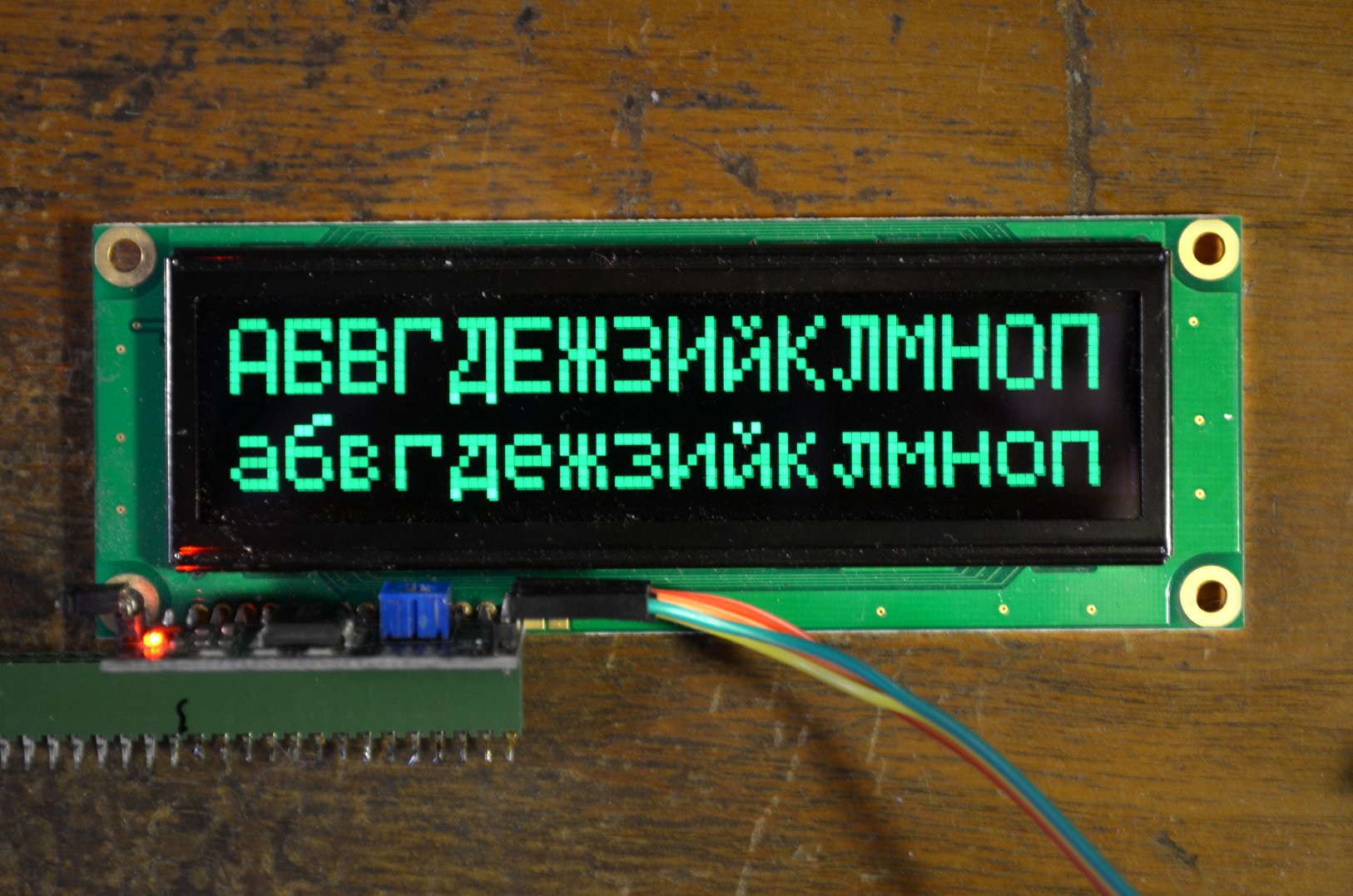
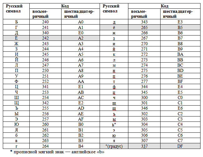
A revised and updated version called LiquidCrystal_I2C_OLED can be downloaded from here . If the string does not contain Russian letters, then it should be output with the usual print () function, which works faster. The degree icon, as well as the letters "" and "" can only be displayed by direct indication of octal codes (for example, "all" - "Sun \ 265", "22.5 °" - "22.5 \ 337", see table below). Examples of output are in the examples folder (do not forget to change the address of the PCF8574 chip if you have a version other than PCF8574A or the address is changed by switching the modification bits). An example of the output of the Russian alphabet on the display of configuration 1602 (chip PCF8574A, default address 0x3F):
The correct output of the first half of the alphabet is shown in the photo:
We emphasize that such a Russified library (as well as LiquidCrystalRus, by the way) is designed to work in modern versions of the Arduino IDE (starting from approximately 1.6.1 and later) in the Windows 7/8/10 environment. In the Arduino IDE 1.0 environment, as well as in other editors and OS operating in single-byte win1251 encoding (ANSI, cp1251), these libraries do not perceive direct Russian text in a line. In this case, use the print () function with the octal codes of Russian letters, according to the table below, only the library will have to use this one anyway (or modify LiquidCrystal_I2C to switch to the ENGLISH_RUSSIAN table during initialization, see here ). The WS0010 controller uses an economical coding method - only Russian letters are entered that do not coincide with English characters. For example, "Saturday" will look like "cy \ 262 \ 262o \ 277a".
Cyrillic character codes and degree icons for the WS0010 controller (ENGLISH_RUSSIAN table, code 0x02)
A sign that your environment / editor gives out instead of UTF-8 single-byte win1251 encoding will be output instead of “A” - “h”, instead of “a” - “D”, etc. (photo sent by Tomasina ):
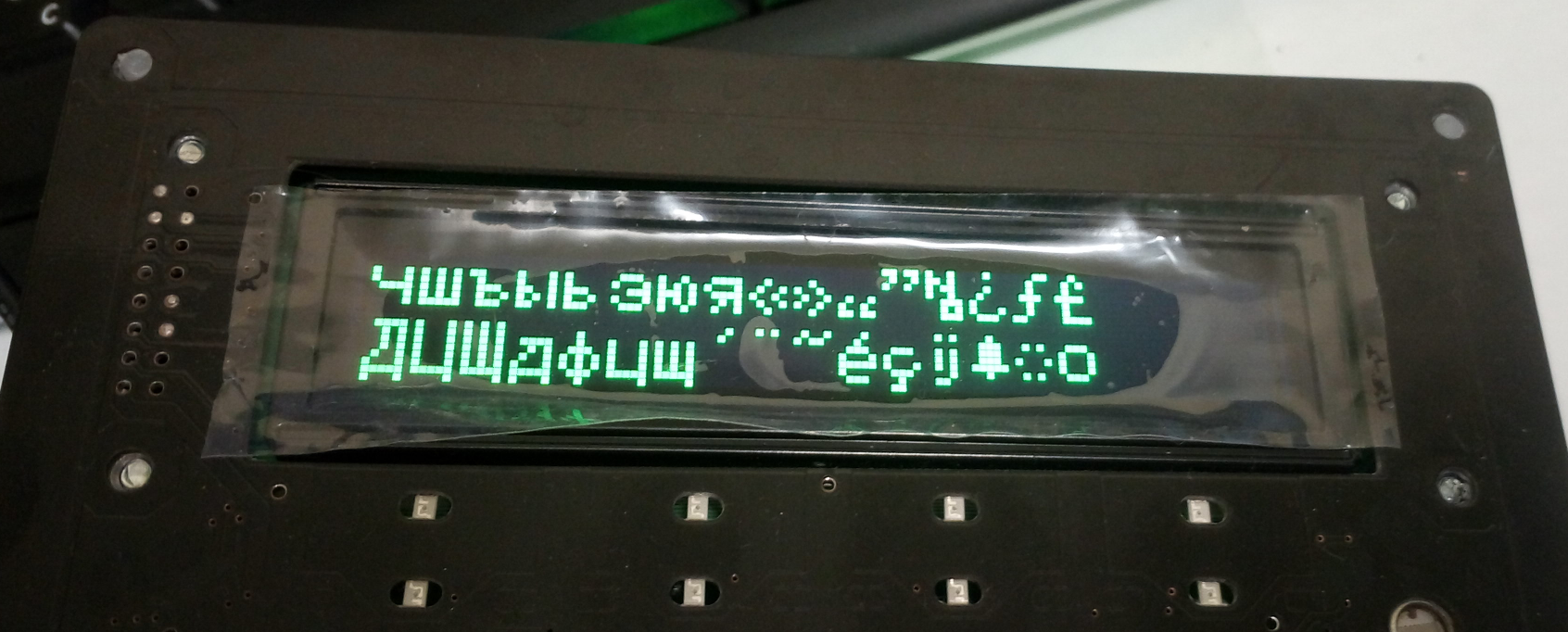
If you don’t cope with finding out the reasons where single-byte encoding is taken from in modern Windows environments, you just have to either use direct output of codes, as mentioned above, or simply change all outtr code UTF-8 to code in my outStr () function from the win1251 table. For example, the case 0x90 operator (the capital “A”) is replaced with case 0xC0 and so on, and the lines that filter the most significant byte (case 0xd0: break; and case 0xd1: break;) must be deleted.
In fact, the PCF8574 chip can be adapted to a large number of very different uses (read buttons, light up LEDs, etc.). In the write mode, the microcircuit directly translates the value of the bits in the byte transmitted on the I2C bus to the state of eight outputs (while reading, on the contrary, the state of eight lines is transmitted to the transmitted byte). The I2C address in PCF8574 can be changed by setting the level on the three inputs of the address assignment, so that using one bus you can set or read up to 64 lines using two wires. In this case, there are some peculiarities due to the asymmetry of the “0” and “1” states of the pins of the parallel port PCF8574, both when working at the input and at the output (see here ), but our task is to control the LCD or OLED displays on the I2C bus, they will not interfere.
There is even no need to dilute the adapter board for the displays yourself. Especially for the management of HD44780-compatible displays, numerous varieties of adapter modules are available (see photo). Along one edge they have a single-row PLS-type pin connector, the wiring of which allows you to directly connect such a module with an LCD or OLED display.

If the module is oriented so that the output of module number 1 (read from the input connector, see photo above) coincides with output 1 of the display, the adapter card can be installed directly on the display board as shown in the photo below (photo with site 9zip.ru). In this case, of course, the pitch of the pins and the type of the connector itself must match. Therefore, among the common Winstar lowercase OLED displays, as in the picture, only WEH1602A and 2004A types can be connected, for type 1602B the module will have to be rotated 180, and for people who are loved by 2002A / B and 1202/1204 to make adapter cables.

The pinout for the OLED display is shown in the table. If you want to connect a microcircuit instead of a ready-made module (which will reduce the size), but you are going to use the library described below, then using this table you can also determine the correct connection of the “bare” microcircuit. Note that a four-wire display connection is actually used here and the bits DB0-DB3 are not connected anywhere, therefore in the table they are marked in gray.
Pinout for connecting PCF8574 and a module based on it to an OLED display

The blue trimmer resistor, as well as the jumper on the end of the board, which are visible in the photo, are designed to control the backlight in LCD displays (pins 15 and 16) and in our case are not activated. (Incidentally, the same applies to bit P3 of the output port of PCF8574, which in our case is not used.) Therefore, when connecting an OLED-display 1602B directly, in which pins 15 and 16 are in front of pin 1, you can simply not connect them (and module while 15 and 16 conclusions will have to be removed so as not to interfere).
Under this resistor, the board has contacts A0, A1 and A2 for setting the low-order bits of the I2C address. By default, they are connected to a high level, so the address has the largest possible value from the specified range. PCF8574 microcircuits are available in several modifications, differing in this range. For PCF8574 without a letter index (or on PCF8574T), the default address will be 0x27, and may change down to 0x20. For PCF8574A, the default address is 0x3F and changes to 0x38.
To work with the display connected via PCF8574 via the I2C interface, there is a recommended library called LiquidCrystal_I2C (see the official website arduino.cc). Of course, like the original LiquidCrystal, it only works with English. There are no Russian-language versions of it (at least, those that would work confidently in modern versions of the Arduino IDE), and there is also no option for working with an OLED display. Therefore, the author undertook the work of revision, taking the simplest of the LiquidCrystal_I2C variants as the initial one.
The obvious method of Russification would be to combine LiquidCrystal_I2C and LiquidCrystalRus, finalizing the latter in part of the initialization of OLED-displays. But the frontal solution does not roll here - in I2C mode, LiquidCrystalRus prints only the first letter sent through the print () function. I didn’t figure out what this is about by simply adding the outStr () output function to the LiquidCrystal_I2C library, which discards the high byte of the UTF-8 encoding, and the low-order code recodes the character from the ENGLISH_RUSSIAN internal table (0x02) of the WS0010 controller.
A revised and updated version called LiquidCrystal_I2C_OLED can be downloaded from here . If the string does not contain Russian letters, then it should be output with the usual print () function, which works faster. The degree icon, as well as the letters "" and "" can only be displayed by direct indication of octal codes (for example, "all" - "Sun \ 265", "22.5 °" - "22.5 \ 337", see table below). Examples of output are in the examples folder (do not forget to change the address of the PCF8574 chip if you have a version other than PCF8574A or the address is changed by switching the modification bits). An example of the output of the Russian alphabet on the display of configuration 1602 (chip PCF8574A, default address 0x3F):
#include <Wire.h> #include <LiquidCrystal_I2C_OLED.h> LiquidCrystal_I2C OLED1(0x3F,16,2); // void setup() { OLED1.init(); OLED1.clear(); OLED1.print("Proba"); // OLED1.setCursor(7, 0); // OLED1.outStr(""); // OLED1.setCursor(7, 1);// OLED1.print("-22,3\337C"); //"-22,3°C" delay(1000); } void loop() {// 162 202!!!! OLED1.setCursor(0, 0); // OLED1.outStr(""); OLED1.setCursor(0, 1);// OLED1.outStr(""); delay(2000); OLED1.setCursor(0, 0); // OLED1.outStr(""); OLED1.setCursor(0, 1);// OLED1.outStr(""); delay(3000); }
The correct output of the first half of the alphabet is shown in the photo:

We emphasize that such a Russified library (as well as LiquidCrystalRus, by the way) is designed to work in modern versions of the Arduino IDE (starting from approximately 1.6.1 and later) in the Windows 7/8/10 environment. In the Arduino IDE 1.0 environment, as well as in other editors and OS operating in single-byte win1251 encoding (ANSI, cp1251), these libraries do not perceive direct Russian text in a line. In this case, use the print () function with the octal codes of Russian letters, according to the table below, only the library will have to use this one anyway (or modify LiquidCrystal_I2C to switch to the ENGLISH_RUSSIAN table during initialization, see here ). The WS0010 controller uses an economical coding method - only Russian letters are entered that do not coincide with English characters. For example, "Saturday" will look like "cy \ 262 \ 262o \ 277a".
Cyrillic character codes and degree icons for the WS0010 controller (ENGLISH_RUSSIAN table, code 0x02)

A sign that your environment / editor gives out instead of UTF-8 single-byte win1251 encoding will be output instead of “A” - “h”, instead of “a” - “D”, etc. (photo sent by Tomasina ):

If you don’t cope with finding out the reasons where single-byte encoding is taken from in modern Windows environments, you just have to either use direct output of codes, as mentioned above, or simply change all outtr code UTF-8 to code in my outStr () function from the win1251 table. For example, the case 0x90 operator (the capital “A”) is replaced with case 0xC0 and so on, and the lines that filter the most significant byte (case 0xd0: break; and case 0xd1: break;) must be deleted.
All Articles