"Machine" vision: what and how cars see
The automotive industry is considered a “pioneer” in the application of machine vision technologies and their largest consumer. According to analysts, the automotive industry forms 23% of the market for computer vision products in Germany. And according to VDMA, for Europe this figure is 21%.
It is therefore not surprising that the algorithms of machine vision gradually began to be used in the cars themselves, and not only at the stages of their production. They are currently used in autopilot and lane recognition technologies.
In today's article we will start talking about what cars are “seeing” and how they do it, using basic algorithms and methods as a starting point for a cycle of stories.
Welcome on board! / WayRay image
Using arrays of sensors and cameras, cars learned to recognize around themselves bumpers, trees, poles and parked vehicles. The principle of determining the distance to objects is based on the parallax of motion .
When we move left or right, objects in the distance are displaced less than the neighbors. Based on this offset, the distance from the observer is determined.
The technique was called structure from motion. On the corresponding page on Wikipedia, several tools are offered for recreating three-dimensional models from a video or a set of photos. The basis is the analysis of the stereo pair.
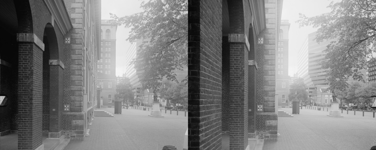
Stereo pair taken by two cameras / photo cobravictor / PD
The stereopair allows you to identify pairs of conjugate points in space, on the basis of which the distance map is constructed. On it, the distance to the object is indicated by shades of gray - the farther, the darker. An example of such an image is in Reinhard Klette of Auckland University of Technology. When the map is built, an analysis of the movement of objects is made (speed, trajectory) - this is needed to determine possible conflicts.
Motion analysis begins with the calculation of the optical flux , which is used to calculate the displacement map. It allows you to track the offset points, that is, to find them on the second image of the stereo pair. Usually this method is used for tracking objects, collision detection and in augmented reality .
From simple methods for determining the shift, the phase correlation method is distinguished - this is the calculation of the Fourier transform for both images and finding their convolution. A block comparison is also used: a shift is found that minimizes the rate of difference of images in the window.
A classic approach to calculating a stream is the Lukas-Canada algorithm. It is based on the assumption that the pixel values move from one frame to the next without any changes. Thus, we assume that the pixels belonging to the same object may shift to the side, but their value will remain unchanged.
Of course, in real conditions the illumination is constantly changing, but in practice this assumption does not greatly affect the result. The theory of the operation of the Lucas-Canada algorithm is described in detail in this article .
This method well defines small shifts within which the picture is similar to its linear approximation. But there are other approaches: the Gunnar Farnebak method, which calculates the flow for the entire image at once, and the Horn-Shranka algorithm , which is based on the hypothesis that the projections of the optical flow are changed.
Read more about building maps of displacements and distances here and here .
Based on the maps obtained, the algorithms build routes and estimate the trajectories: avoiding collisions, maneuvering. Algorithms build probabilistic models to predict the routes of objects around.
When autopiloting, the system builds an approximate route plan to the destination point and regularly monitors the environment. The vehicle determines the direction in which it can proceed, taking into account the current speed and the angular position.
Then it eliminates routes intersecting with obstacles or approaching them too closely. The safety of the maneuver is also evaluated. For example, a car moving at a speed of 90 km / h cannot turn sharply right after 5 meters.
When the path is chosen, the vehicle controller commands the accelerator, brakes, steering system and power drives.
Note that there are other ways to determine the distance to obstacles and avoid collisions. Their appearance and implementation will be possible with the spread of the Internet of things. These algorithms work in a different way - their authors suggest using not “cameras”, but “car-to-car” and “car-infrastructure” communication systems.
The algorithm of Decentralized Reactive Collision Avoidance assumes that if cars are at a great distance from each other, they follow the planned routes. If the cars get closer, the system performs a collision avoidance maneuver. The block diagram is as follows:

/ Block diagram of the DRCA algorithm
To determine whether cars collide, DRCA uses the collision cone concept described by the velocity vectors. If the angle β between the relative position vector r ⌄ ij and the relative velocity vector v ⌄ ij is greater than or equal to α - the angle between the relative position vector and the end of the collision cone, then there is no conflict of routes.
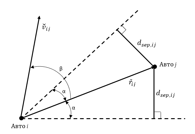
/ The collision cone is the angle between the dotted lines. If the vector v is in this zone, then the cars "conflict"
The algorithm helps to drive around static objects, but it is not suitable if the vehicles move in formations. DRCA will offer cars to dial a safe distance relative to each other and "break" the system.
May be used in combination with DRCA. It is based on the calculation of artificial force fields. Cars are charged particles. Particles with the same charge repel, and with the opposite - they attract. Therefore, cars are assigned negative charges, and their desired routes are positive. Power vectors are calculated based on these charges, and then used to determine the direction of motion.
Several methods are used to evaluate the vectors of the force of attraction. Yunior I. Cruz from the University of Washington in his work describes a technique that was also proposed for paving the route of aircraft with unchangeable wing geometry.
An oval “safety zone” is formed around the vehicle, beyond which the influence of the “charges” of other vehicles becomes insignificant. The attraction force of the destination point is considered constant. All this allows us to estimate the force of attraction that cars “sense” and, on the basis of these data, correct the route.
Cars also use computer vision to determine the lane. They learned how to warn the driver about hitting the markup and even correct the trajectory on their own. Scientists are considering several options for implementing this functionality. The first is when the infrastructure is part of intelligent systems (smart beacons are used), but it is associated with the complexity and high cost of road rebuilding. Second - the cars themselves analyze the road and make decisions.
Such systems use cameras and characterization techniques for marking strip boundaries. First, in the picture from the camera, find the lines located at a certain angle to the lens. After that, the selected pixels are allocated at the extreme pixels using a ternary search.
Next is the selection of useful information. The fact is that the system marks all the lines that satisfy the specified conditions. How this looks, you can see in the work of Luke Fletcher (Luke Fletcher) on the link .
Companies address this problem differently. For example, Suzuki uses projective transformation. The camera projects two lines that converge at a perspective point. The system takes into account only those bands that are parallel to the projected. However, this does not save from the allocation of cracks on the asphalt, which run along the road.
Another way to identify bands is called the Bird's Eye (Bird's Eye) and is described in the book "Mathematical Morphology and Its Application to Signal and Image Processing". The algorithm starts working by converting an image into an orthographic projection, as if turning the image vertically. After that, lanes are also selected and distance fields are calculated, for example, using the Euclidean transformation .
Other algorithms rely on finding regions that change color from black to white, but this approach should not be used only, since the quality of the markings on different roads is different. Therefore, researchers recommend the use of combined methods.
The recognition algorithm with the construction of binary images and the code can be found at the link to GitHub . The presented project is part of the program Udacity Self-Driving Car Nanodegree . Another example with pieces of code from the library of algorithms OpenCV you can find here .
It is therefore not surprising that the algorithms of machine vision gradually began to be used in the cars themselves, and not only at the stages of their production. They are currently used in autopilot and lane recognition technologies.
In today's article we will start talking about what cars are “seeing” and how they do it, using basic algorithms and methods as a starting point for a cycle of stories.
Welcome on board! / WayRay image
See obstacles
Using arrays of sensors and cameras, cars learned to recognize around themselves bumpers, trees, poles and parked vehicles. The principle of determining the distance to objects is based on the parallax of motion .
When we move left or right, objects in the distance are displaced less than the neighbors. Based on this offset, the distance from the observer is determined.
The technique was called structure from motion. On the corresponding page on Wikipedia, several tools are offered for recreating three-dimensional models from a video or a set of photos. The basis is the analysis of the stereo pair.
Stereo pair taken by two cameras / photo cobravictor / PD
The stereopair allows you to identify pairs of conjugate points in space, on the basis of which the distance map is constructed. On it, the distance to the object is indicated by shades of gray - the farther, the darker. An example of such an image is in Reinhard Klette of Auckland University of Technology. When the map is built, an analysis of the movement of objects is made (speed, trajectory) - this is needed to determine possible conflicts.
Motion analysis begins with the calculation of the optical flux , which is used to calculate the displacement map. It allows you to track the offset points, that is, to find them on the second image of the stereo pair. Usually this method is used for tracking objects, collision detection and in augmented reality .
From simple methods for determining the shift, the phase correlation method is distinguished - this is the calculation of the Fourier transform for both images and finding their convolution. A block comparison is also used: a shift is found that minimizes the rate of difference of images in the window.
A classic approach to calculating a stream is the Lukas-Canada algorithm. It is based on the assumption that the pixel values move from one frame to the next without any changes. Thus, we assume that the pixels belonging to the same object may shift to the side, but their value will remain unchanged.
Of course, in real conditions the illumination is constantly changing, but in practice this assumption does not greatly affect the result. The theory of the operation of the Lucas-Canada algorithm is described in detail in this article .
This method well defines small shifts within which the picture is similar to its linear approximation. But there are other approaches: the Gunnar Farnebak method, which calculates the flow for the entire image at once, and the Horn-Shranka algorithm , which is based on the hypothesis that the projections of the optical flow are changed.
Read more about building maps of displacements and distances here and here .
Based on the maps obtained, the algorithms build routes and estimate the trajectories: avoiding collisions, maneuvering. Algorithms build probabilistic models to predict the routes of objects around.
When autopiloting, the system builds an approximate route plan to the destination point and regularly monitors the environment. The vehicle determines the direction in which it can proceed, taking into account the current speed and the angular position.
Then it eliminates routes intersecting with obstacles or approaching them too closely. The safety of the maneuver is also evaluated. For example, a car moving at a speed of 90 km / h cannot turn sharply right after 5 meters.
When the path is chosen, the vehicle controller commands the accelerator, brakes, steering system and power drives.
Note that there are other ways to determine the distance to obstacles and avoid collisions. Their appearance and implementation will be possible with the spread of the Internet of things. These algorithms work in a different way - their authors suggest using not “cameras”, but “car-to-car” and “car-infrastructure” communication systems.
DRCA algorithm
The algorithm of Decentralized Reactive Collision Avoidance assumes that if cars are at a great distance from each other, they follow the planned routes. If the cars get closer, the system performs a collision avoidance maneuver. The block diagram is as follows:
/ Block diagram of the DRCA algorithm
To determine whether cars collide, DRCA uses the collision cone concept described by the velocity vectors. If the angle β between the relative position vector r ⌄ ij and the relative velocity vector v ⌄ ij is greater than or equal to α - the angle between the relative position vector and the end of the collision cone, then there is no conflict of routes.
/ The collision cone is the angle between the dotted lines. If the vector v is in this zone, then the cars "conflict"
The algorithm helps to drive around static objects, but it is not suitable if the vehicles move in formations. DRCA will offer cars to dial a safe distance relative to each other and "break" the system.
The method of artificial force fields
May be used in combination with DRCA. It is based on the calculation of artificial force fields. Cars are charged particles. Particles with the same charge repel, and with the opposite - they attract. Therefore, cars are assigned negative charges, and their desired routes are positive. Power vectors are calculated based on these charges, and then used to determine the direction of motion.
Several methods are used to evaluate the vectors of the force of attraction. Yunior I. Cruz from the University of Washington in his work describes a technique that was also proposed for paving the route of aircraft with unchangeable wing geometry.
An oval “safety zone” is formed around the vehicle, beyond which the influence of the “charges” of other vehicles becomes insignificant. The attraction force of the destination point is considered constant. All this allows us to estimate the force of attraction that cars “sense” and, on the basis of these data, correct the route.
Recognize stripes
Cars also use computer vision to determine the lane. They learned how to warn the driver about hitting the markup and even correct the trajectory on their own. Scientists are considering several options for implementing this functionality. The first is when the infrastructure is part of intelligent systems (smart beacons are used), but it is associated with the complexity and high cost of road rebuilding. Second - the cars themselves analyze the road and make decisions.
Such systems use cameras and characterization techniques for marking strip boundaries. First, in the picture from the camera, find the lines located at a certain angle to the lens. After that, the selected pixels are allocated at the extreme pixels using a ternary search.
Next is the selection of useful information. The fact is that the system marks all the lines that satisfy the specified conditions. How this looks, you can see in the work of Luke Fletcher (Luke Fletcher) on the link .
Companies address this problem differently. For example, Suzuki uses projective transformation. The camera projects two lines that converge at a perspective point. The system takes into account only those bands that are parallel to the projected. However, this does not save from the allocation of cracks on the asphalt, which run along the road.
Another way to identify bands is called the Bird's Eye (Bird's Eye) and is described in the book "Mathematical Morphology and Its Application to Signal and Image Processing". The algorithm starts working by converting an image into an orthographic projection, as if turning the image vertically. After that, lanes are also selected and distance fields are calculated, for example, using the Euclidean transformation .
Other algorithms rely on finding regions that change color from black to white, but this approach should not be used only, since the quality of the markings on different roads is different. Therefore, researchers recommend the use of combined methods.
The recognition algorithm with the construction of binary images and the code can be found at the link to GitHub . The presented project is part of the program Udacity Self-Driving Car Nanodegree . Another example with pieces of code from the library of algorithms OpenCV you can find here .
All Articles