Field Amateur Hardware
If in the first publication we talked about the general theory of amateur radio work in the field, today we will talk about the technical support of field trips, consider our supply equipment, communication equipment and of course antenna-feeder facilities.
In the open field or on the banks of the river amateur radio virtually no place to take electricity, you have to bring it with you in one form or another. And the very first thing that comes to mind is an electric generator. Of course, we also carry it with us, we have a Fubag TI 2600 inverter gasoline generator, its 2300 W power is more than enough to power all of our equipment, as well as lighting, enough for the future, and to power the amplifier, which we plan to take in the field from next year.
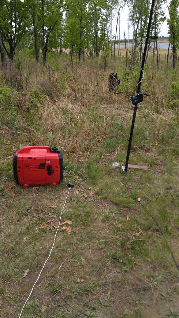
Usually, the generator is installed 20-30 meters away from SHEK, somewhere under the river bank, so that the smoke would not make much noise and the breeze would blow away, the generator must be grounded to reduce interference. Since most radio amateur transceivers have a supply voltage of 13.8V, in the case of generator power, networked power supplies, usually pulsed due to their low weight and size, convert 230V produced by the generator to the constant 13.8V required by the transceiver. Power supply at 13.8V makes it very easy to directly connect the transceivers to the batteries and the car’s on-board network, as described below.
The second most frequently used, but far from important, means is batteries. The generator on the low-frequency bands, partially on 40 meters, but especially on 80 and 160, begins to make noise on the radio, this is manifested in annoying cod. Therefore, at 80 we usually operate from batteries pre-charged at home, these are ordinary lead batteries at 40-120 Ah, from the car and from the base cellular stations, the latter are especially convenient, they are tall and flat, with convenient carrying handles and large capacity.
Third, the onboard vehicle network. This method of power supply is usually used when departing for several hours in the field in winter, when a light single-band antenna is deployed and work is carried out from the salol of the car. The engine heats you and feeds the equipment. A low-power transceiver up to 60W is usually powered directly from the cigarette lighter, the current provided by the cigarette lighter is sufficient. A more powerful 100W transceiver is already necessary to connect with a cable from the battery, because the current consumption here is already about 20A.
Not to mention the solar energy. Unfortunately, in our practice, we practically do not use it. Certain experiments in this regard were carried out by our colleague, several solar batteries with a total area of about 2 square meters (unfortunately the exact current and voltage parameters and the type of batteries are not known to me) charged the batteries during the day, but as far as I know any serious charge the battery then we could not and the current consumption of the transceiver, we put it quickly enough. In general, solar charging seems to me quite an interesting topic, but most likely not with lead batteries. Unfortunately, there is no possibility to check this in detail at the moment.
Standard radio amateur transceivers are usually quite large, heavy, and we usually do not carry them in the field. Now in the field we use two devices, this is the Yaesu FT-857D and the SW-2013 transceiver, which is a development of the Ukrainian radio amateur. Both of these transceivers are capable of operating on all amateur HF bands, as well as on the UHF band 2m. The first gives out power up to 100W and is our main, the second gives up to 60W depending on the range.

In this photo at the bottom left you can see the SW-2013 transceiver and the Yaesu FT-900 transceiver, which we also took to work in the field.
What I like about SW-2013 is its excellent performance in sensitivity and dynamic range, with its very small dimensions and weight.
Well, the Yaesu FT-857D transceiver doesn’t need a presentation at all, it’s a workhorse that many hams know and love for its reliability, power, size and excellent ergonomics.

I would very much like to try working in the field on SDR transceivers in the field, but here the financial side of the issue affects everything, good SDRs are not quite cheap yet.
Sometimes we also take with us a SWR / power meter. Not to say that it would be so necessary, because before starting work we check all antennas and adjust them to the minimum of the CWS, but sometimes it's nice to look at the moving arrows.
This device is connected between the transceiver and the antenna. It can be seen in the photo above, in the same place where the Yaesu FT-857D is.
It is also mandatory in the field with a laptop is taken, it is needed to work with digital types of communication as well as for logging. Given that now most of the territory is covered by cellular communication, the laptop also connects to the Internet to access amateur clusters.
An antenna analyzer is mandatory, it allows you to test and adjust antennas to minimize the VSWR before starting.
We constantly use different devices in our work, for example, my homemade graphic SWR meter

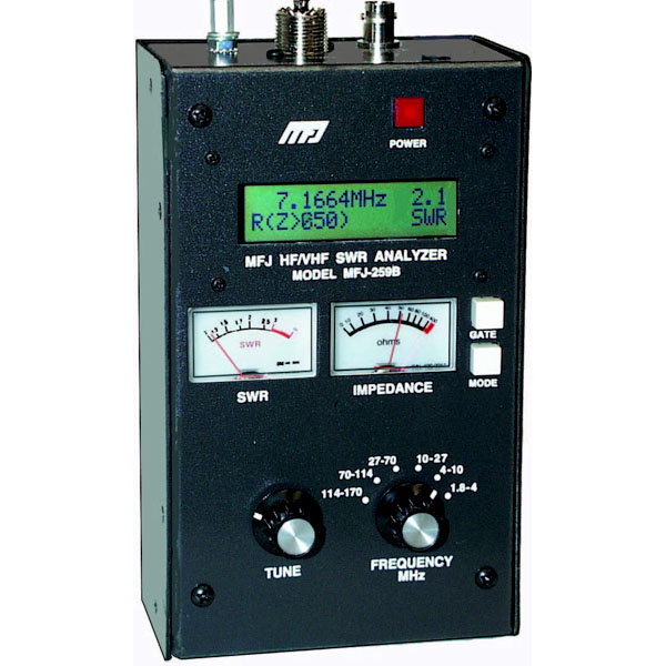
As well as antenna analyzers AA-330 and MFJ-259B

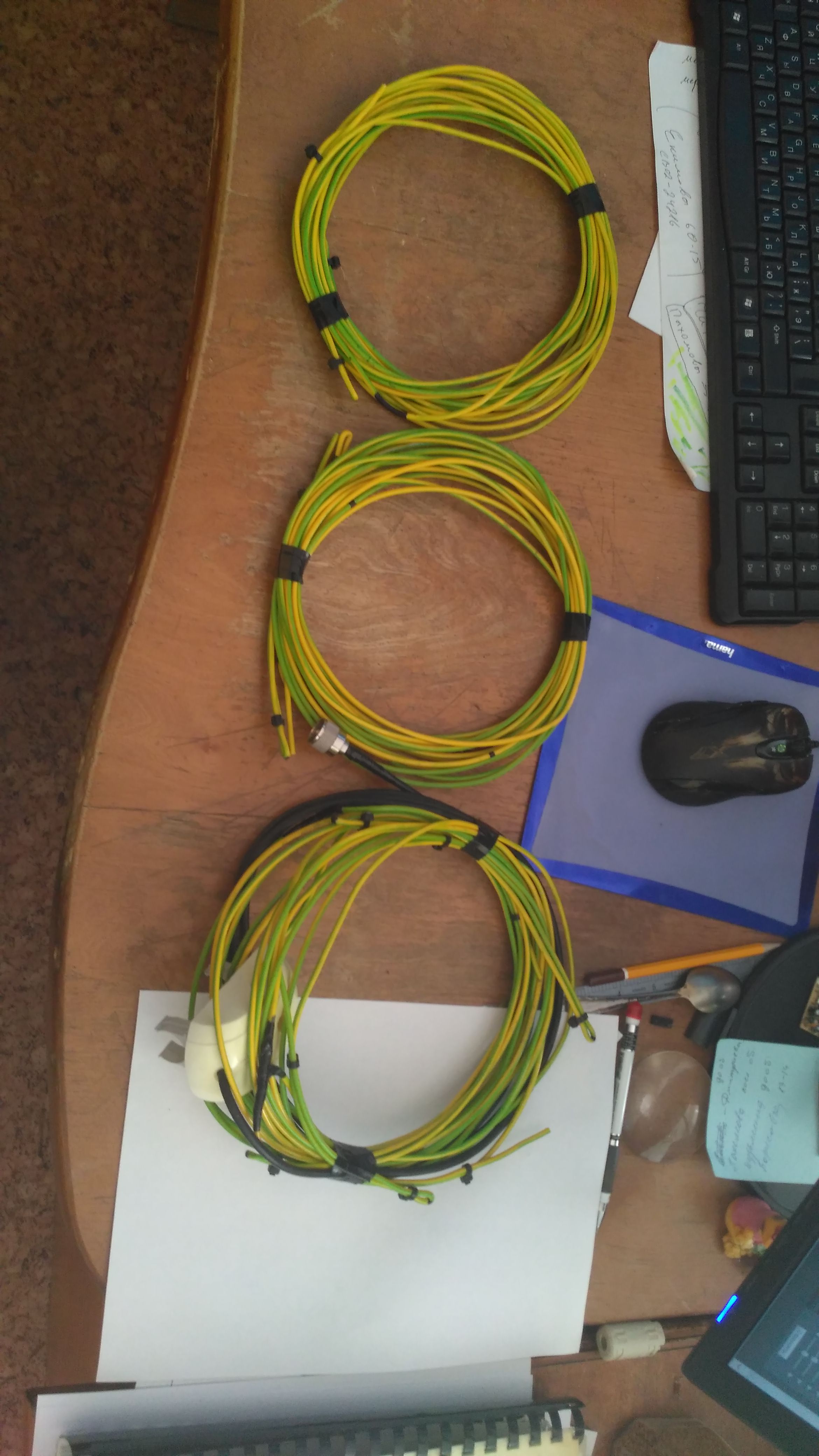
Let's start with the feeders, everything is simple, these are ordinary coaxial cables with a characteristic impedance of 50 Ohms, terminated on both sides with PL-259 connectors from 10 to 30 meters long. Plus, the same connecting cables with a length of 1-2 meters.
Next come the antenna switches, also a very simple purely mechanical device designed to connect several (2-3) to one transceiver or to switch several transceivers to one antenna. It can be seen in the photo above, where I showed the SW-2013 transceiver, the blue box lying on the table between the transceivers, there it is in two positions, there are also three or more

Well, finally the most interesting, antennas. Three types of antennas are usually shipped to the field; they are verticals, dipoles, and directional antennas of the Yagi type. Almost all of our antennas we do ourselves. Although there is in our set and a couple of factory.
Let's start with verticals, the simplest vertical is a 6 meter long fishing rod, a 5.2 meter long wire is vertically tensioned along it, the second same wire is stretched horizontally at 1 meter from the ground towards the correspondent. It turns out the simplest vertical of 20 meters with one counterweight. It is used by me for departures for a couple of hours in the field in the winter, as it is extremely quickly installed and configured once it requires almost no adjustment in the future. In spite of the simplest construction, I have connections to it on highways with a length of up to 7 thousand kilometers.
This antenna looks like this

after work it is easy to roll up and take off until the next departure.
For the same winter trips my factory and MFJ-1620T antenna is used by my colleague and partner RA0JDI

I will not tell a lot about dipoles, we practically don’t use them, we have two Windom-type antennas from the company Radial and a homemade dipole on the 80 meter range.
And now the most interesting - directional antennas. All our directional antennas are different wire antenna options. Wire antennas are good because they fold very compactly and are lightweight. They are bad because the deployment of elements requires rigid parts or numerous stretch marks.
Let's start with a double vertical delta. Here is its diagram (range 20 meters):
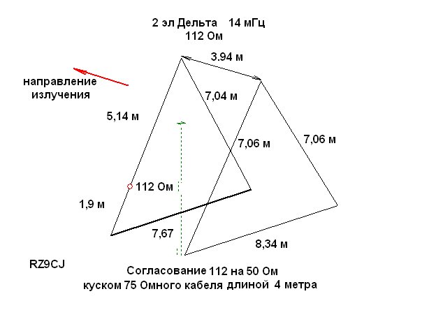
Structurally, it consists of two vertically standing fishing rods, each of which has vertically stretched triangles, the corners of triangles are fixed with braces. This antenna is good due to the fact that due to the closed structure of the elements it is susceptible to interference, and also provides a relatively low ground suspension.
Unfortunately, I don’t have a good photo of this antenna, but I don’t see something inferior that makes sense; everything is clear according to the scheme.
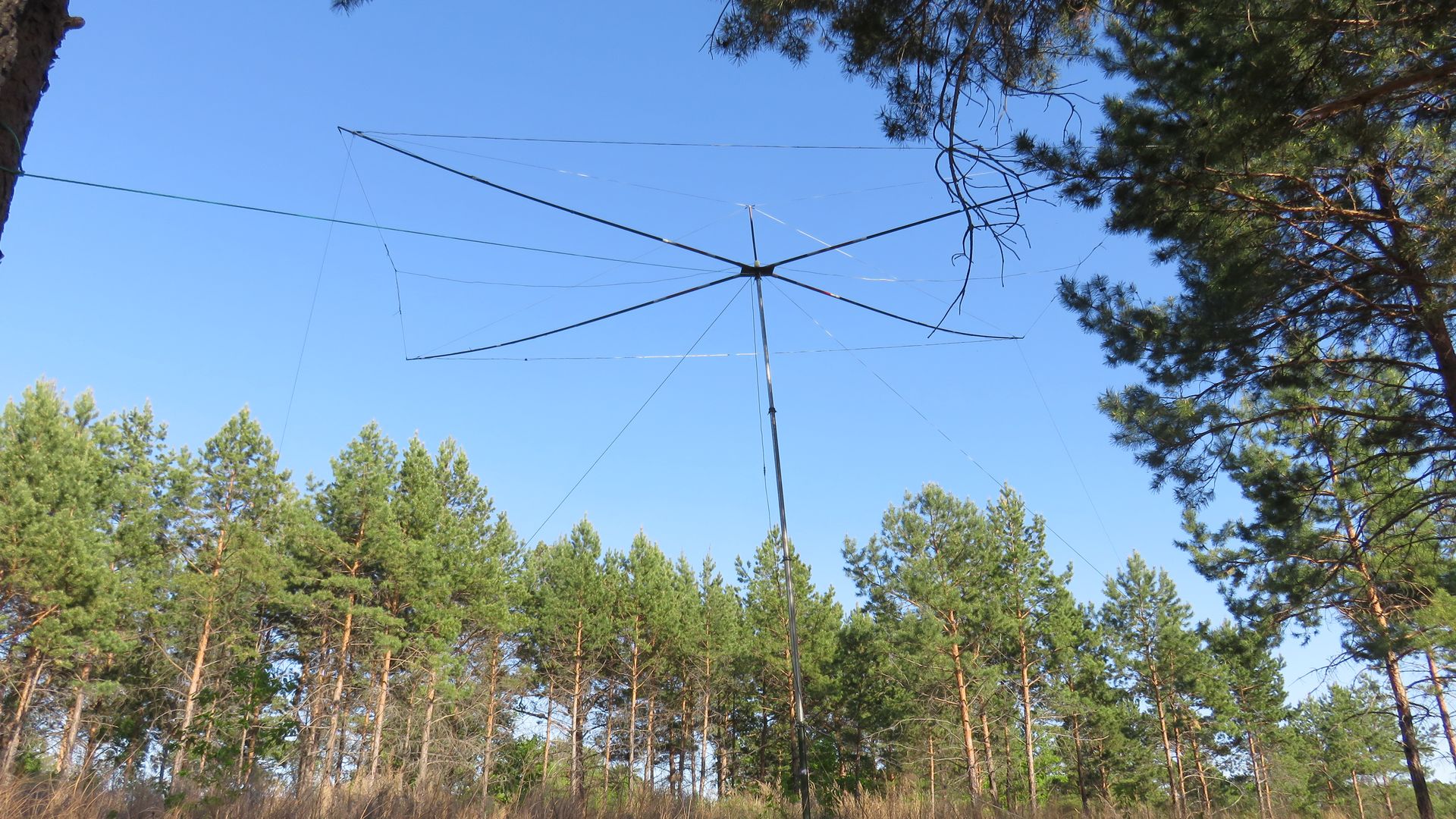
Further, the antenna type Hex Beam, in my first publication, I called it Spider, this is not quite the correct name.
Schematically, this antenna looks like this:

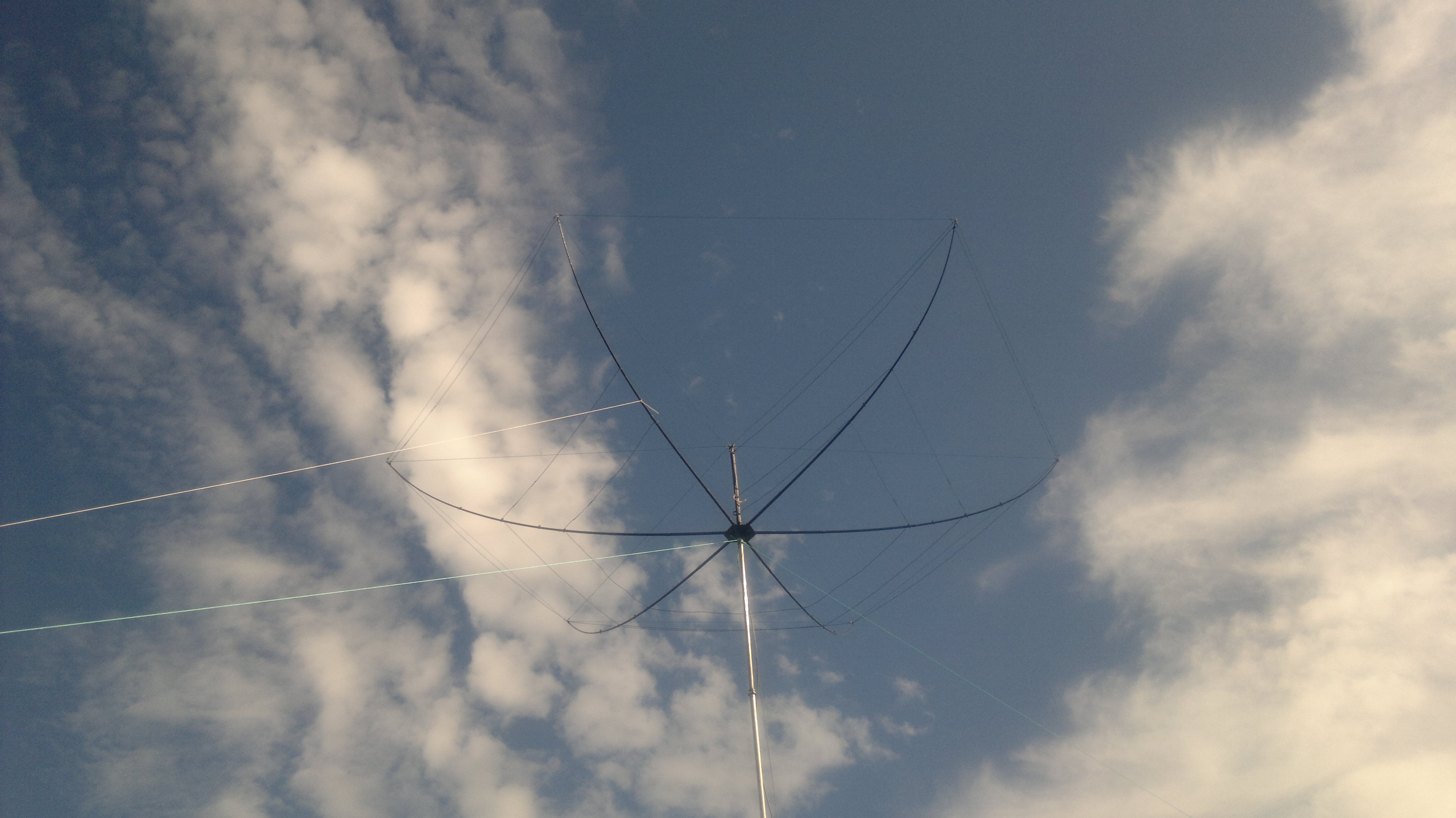
Structurally, this is a hexagonal plate of the base into which 6 fishing rods are placed located around the circumference, all the fishing rods are curved upwards with the help of upper drawbars, an inverted umbrella is obtained, onto which elements of all six ranges are already attached. The elements themselves are wire curved. And the whole structure as a whole is a two-element six-band antenna for the ranges of 6-10-12-15-17-20 meters.
Unfortunately, the photos of the process of its construction and the detailed device have not been preserved, I post its photo in work.


Finally, our relatively new antenna. In her work, she is the first season but has already shown herself perfectly. This is a three-element Yagi wire for one 20 meter range with bent director and reflector and a shortened vibrator with T-loads at the ends. The gain of this antenna is higher than the previous one and, of course, cannot be compared with the vertical and dipole. This antenna works, what is called, like a cannon, well, yes it is not surprising, almost full-size 3-element yaga for 20 is strong.
Here is its scheme:

And here is the central node of this antenna in my version:

As you can see here the cross in which four rods are inserted. The drawn-out fishing rods are supported by vertical braces, and already at the ends and in the middle the wire elements are strung. All this is going to the field alone in 15-20 minutes. After disassembly, it is compact enough. Here is a photo of all minimized items:
Now it is our main long-range antenna at 20 meters.
This will finish the review of our antennas. Behind the scenes, there are quite a lot of various designs, this is both the Inverted-V and the horizontal delta and other antennas that have been made, have been tried, but are not used for various reasons.
We should also mention the VHF antenna for 2 meters, but this is a topic for another post, since here I wanted to tell and show exactly about the work on the HF.
Power supply
In the open field or on the banks of the river amateur radio virtually no place to take electricity, you have to bring it with you in one form or another. And the very first thing that comes to mind is an electric generator. Of course, we also carry it with us, we have a Fubag TI 2600 inverter gasoline generator, its 2300 W power is more than enough to power all of our equipment, as well as lighting, enough for the future, and to power the amplifier, which we plan to take in the field from next year.
Usually, the generator is installed 20-30 meters away from SHEK, somewhere under the river bank, so that the smoke would not make much noise and the breeze would blow away, the generator must be grounded to reduce interference. Since most radio amateur transceivers have a supply voltage of 13.8V, in the case of generator power, networked power supplies, usually pulsed due to their low weight and size, convert 230V produced by the generator to the constant 13.8V required by the transceiver. Power supply at 13.8V makes it very easy to directly connect the transceivers to the batteries and the car’s on-board network, as described below.
The second most frequently used, but far from important, means is batteries. The generator on the low-frequency bands, partially on 40 meters, but especially on 80 and 160, begins to make noise on the radio, this is manifested in annoying cod. Therefore, at 80 we usually operate from batteries pre-charged at home, these are ordinary lead batteries at 40-120 Ah, from the car and from the base cellular stations, the latter are especially convenient, they are tall and flat, with convenient carrying handles and large capacity.
Third, the onboard vehicle network. This method of power supply is usually used when departing for several hours in the field in winter, when a light single-band antenna is deployed and work is carried out from the salol of the car. The engine heats you and feeds the equipment. A low-power transceiver up to 60W is usually powered directly from the cigarette lighter, the current provided by the cigarette lighter is sufficient. A more powerful 100W transceiver is already necessary to connect with a cable from the battery, because the current consumption here is already about 20A.
Not to mention the solar energy. Unfortunately, in our practice, we practically do not use it. Certain experiments in this regard were carried out by our colleague, several solar batteries with a total area of about 2 square meters (unfortunately the exact current and voltage parameters and the type of batteries are not known to me) charged the batteries during the day, but as far as I know any serious charge the battery then we could not and the current consumption of the transceiver, we put it quickly enough. In general, solar charging seems to me quite an interesting topic, but most likely not with lead batteries. Unfortunately, there is no possibility to check this in detail at the moment.
Communications equipment
Standard radio amateur transceivers are usually quite large, heavy, and we usually do not carry them in the field. Now in the field we use two devices, this is the Yaesu FT-857D and the SW-2013 transceiver, which is a development of the Ukrainian radio amateur. Both of these transceivers are capable of operating on all amateur HF bands, as well as on the UHF band 2m. The first gives out power up to 100W and is our main, the second gives up to 60W depending on the range.
In this photo at the bottom left you can see the SW-2013 transceiver and the Yaesu FT-900 transceiver, which we also took to work in the field.
What I like about SW-2013 is its excellent performance in sensitivity and dynamic range, with its very small dimensions and weight.
Well, the Yaesu FT-857D transceiver doesn’t need a presentation at all, it’s a workhorse that many hams know and love for its reliability, power, size and excellent ergonomics.
I would very much like to try working in the field on SDR transceivers in the field, but here the financial side of the issue affects everything, good SDRs are not quite cheap yet.
Sometimes we also take with us a SWR / power meter. Not to say that it would be so necessary, because before starting work we check all antennas and adjust them to the minimum of the CWS, but sometimes it's nice to look at the moving arrows.
This device is connected between the transceiver and the antenna. It can be seen in the photo above, in the same place where the Yaesu FT-857D is.
It is also mandatory in the field with a laptop is taken, it is needed to work with digital types of communication as well as for logging. Given that now most of the territory is covered by cellular communication, the laptop also connects to the Internet to access amateur clusters.
An antenna analyzer is mandatory, it allows you to test and adjust antennas to minimize the VSWR before starting.
We constantly use different devices in our work, for example, my homemade graphic SWR meter
As well as antenna analyzers AA-330 and MFJ-259B
Antenna-feeder economy
Let's start with the feeders, everything is simple, these are ordinary coaxial cables with a characteristic impedance of 50 Ohms, terminated on both sides with PL-259 connectors from 10 to 30 meters long. Plus, the same connecting cables with a length of 1-2 meters.
Next come the antenna switches, also a very simple purely mechanical device designed to connect several (2-3) to one transceiver or to switch several transceivers to one antenna. It can be seen in the photo above, where I showed the SW-2013 transceiver, the blue box lying on the table between the transceivers, there it is in two positions, there are also three or more
Well, finally the most interesting, antennas. Three types of antennas are usually shipped to the field; they are verticals, dipoles, and directional antennas of the Yagi type. Almost all of our antennas we do ourselves. Although there is in our set and a couple of factory.
Let's start with verticals, the simplest vertical is a 6 meter long fishing rod, a 5.2 meter long wire is vertically tensioned along it, the second same wire is stretched horizontally at 1 meter from the ground towards the correspondent. It turns out the simplest vertical of 20 meters with one counterweight. It is used by me for departures for a couple of hours in the field in the winter, as it is extremely quickly installed and configured once it requires almost no adjustment in the future. In spite of the simplest construction, I have connections to it on highways with a length of up to 7 thousand kilometers.
This antenna looks like this
after work it is easy to roll up and take off until the next departure.
For the same winter trips my factory and MFJ-1620T antenna is used by my colleague and partner RA0JDI
I will not tell a lot about dipoles, we practically don’t use them, we have two Windom-type antennas from the company Radial and a homemade dipole on the 80 meter range.
And now the most interesting - directional antennas. All our directional antennas are different wire antenna options. Wire antennas are good because they fold very compactly and are lightweight. They are bad because the deployment of elements requires rigid parts or numerous stretch marks.
Let's start with a double vertical delta. Here is its diagram (range 20 meters):
Structurally, it consists of two vertically standing fishing rods, each of which has vertically stretched triangles, the corners of triangles are fixed with braces. This antenna is good due to the fact that due to the closed structure of the elements it is susceptible to interference, and also provides a relatively low ground suspension.
Unfortunately, I don’t have a good photo of this antenna, but I don’t see something inferior that makes sense; everything is clear according to the scheme.
Further, the antenna type Hex Beam, in my first publication, I called it Spider, this is not quite the correct name.
Schematically, this antenna looks like this:
Structurally, this is a hexagonal plate of the base into which 6 fishing rods are placed located around the circumference, all the fishing rods are curved upwards with the help of upper drawbars, an inverted umbrella is obtained, onto which elements of all six ranges are already attached. The elements themselves are wire curved. And the whole structure as a whole is a two-element six-band antenna for the ranges of 6-10-12-15-17-20 meters.
Unfortunately, the photos of the process of its construction and the detailed device have not been preserved, I post its photo in work.
Finally, our relatively new antenna. In her work, she is the first season but has already shown herself perfectly. This is a three-element Yagi wire for one 20 meter range with bent director and reflector and a shortened vibrator with T-loads at the ends. The gain of this antenna is higher than the previous one and, of course, cannot be compared with the vertical and dipole. This antenna works, what is called, like a cannon, well, yes it is not surprising, almost full-size 3-element yaga for 20 is strong.
Here is its scheme:
And here is the central node of this antenna in my version:
As you can see here the cross in which four rods are inserted. The drawn-out fishing rods are supported by vertical braces, and already at the ends and in the middle the wire elements are strung. All this is going to the field alone in 15-20 minutes. After disassembly, it is compact enough. Here is a photo of all minimized items:
Now it is our main long-range antenna at 20 meters.
This will finish the review of our antennas. Behind the scenes, there are quite a lot of various designs, this is both the Inverted-V and the horizontal delta and other antennas that have been made, have been tried, but are not used for various reasons.
We should also mention the VHF antenna for 2 meters, but this is a topic for another post, since here I wanted to tell and show exactly about the work on the HF.
All Articles