Horizontal grinding machine
Introduction

This article describes the process of designing and creating a horizontal grinding machine for wood. The emphasis in the presentation of the material is placed on the features of the manufacture and implementation of similar products in the material in the framework of the hobby workshop.
Prehistory At one time I was making traditional bows. To obtain the required tensile strength and ensure the quality of gluing, it was necessary to precisely calibrate narrow and long strips of veneer of solid wood. I did not have a highly specialized machine for such tasks, I managed with devices and services of third parties.
Getting started, I set myself the following goals and objectives: to create a functional, convenient, reliable, maintainable, compact, aesthetic product that can perform tasks intended for it.
The range of tasks was outlined as follows: to be able to get a ground surface with a tolerance of 0.1 mm in thickness over the entire length and width of the workpiece.
In general, the purpose of such machines is the following (if to speak very simply): at the entrance you have a curved workpiece with untreated surfaces - ground at the exit, with parallel planes.
Construction
So, the idea is laid, we begin the process. In my opinion, the design and construction stage of such a product is the most complex and creative part of the entire manufacturing cycle. A master plan is being prepared; conflicting requirements are summarized and combined; lays all the main stages of manufacturing, assembly and operation; possible problems and solutions are foreseen.
I started with the layout and “analysis of competitors”: I looked at who, what and how did this. And after accumulating information, he drew diagrams and sketches in a regular notebook. My main focus at this stage was on the mutual arrangement of the three parts of the machine: engine, drum and feed table. I wanted to make the design compact and light, and, at the same time, not to lose in the convenience of assembly, operation and maintenance. I have to say right away that not everything has been implemented in life, but the main thing is that I realized in more detail these requirements and received the experience of translating them into a particular product. This project was conceived for self-education and gaining practical experience in the design of production machines and devices.
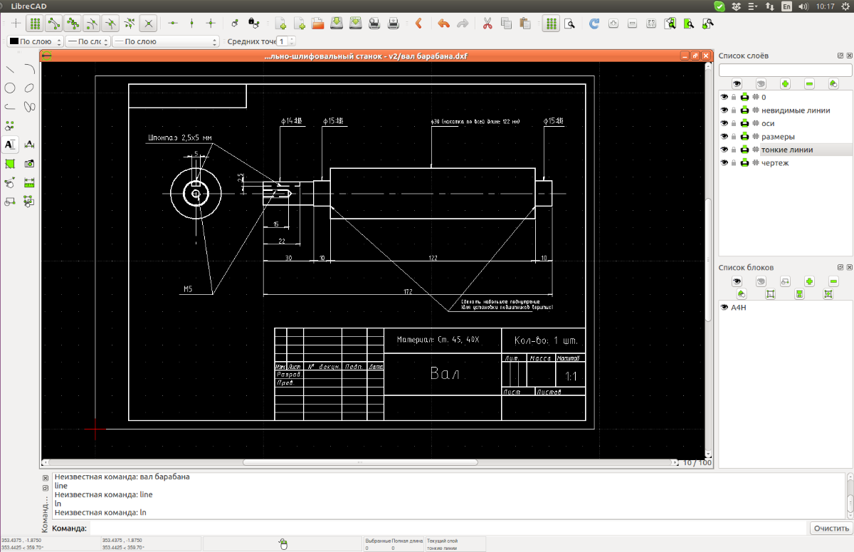
Drawing
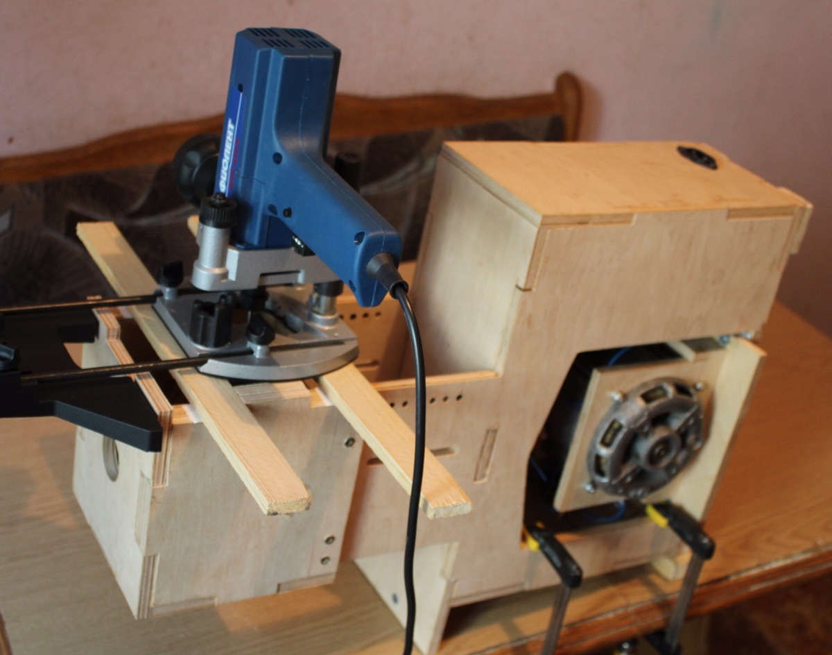
After choosing the concept of layout elements, began their detailed study in the drawings. Those. I had to draw a body, an engine, a grinding drum, a feed table (for blanks), auxiliary handles, clamps, fasteners, a belt drive, user protection from rotating parts, dust removal. In the case required to leave space for the electrics. It was also worth thinking about the possibility of assembling and disassembling it all together, and quickly reconfiguring to a different size during operation.
The difficulty of this stage lies in the fact that you connect the different stages in your mind. For example, to set the dimensions of the hull, you need to know the dimensions of the engine and the grinding drum. But the size of the drum depends (in turn) on the maximum possible width of the workpiece, and the maximum width of the workpiece depends on the engine power. Engine power affects the weight of the product and the dimensions of the case. Placement of the drum over the engine is limited by the presence of a V-belt of the appropriate length. Etc.
All the drawings I did on paper, went on the principle of "from the general to the particular." I set restrictions on a specific part of the machine (for example, a delivery table), and then I detailed this element, put it into components. After bringing all the mutual dimensions together, he made detailed drawings for cutting.


Specialized computer programs
They were used. And they were used precisely as a tool - to translate thoughts into a form that is understandable for another person or machine.
I used the LibreCAD program to create 2D drawings for cutting plywood and create paper drawings for turners and milling machines. I recommend this program to everyone - you can learn literally in a couple of hours (if you know the basics), for free, intuitively clear, simple and logical.
I also tried to create a 3D model of the machine in the FreeCAD program. I mastered the interface, the possibilities, created the first part - but then I abandoned it. For the case when the customer, designer, performer and assembler is one person, there is no need to build a 3D model.
I also looked closely at Autodesk Fusion 360. I would probably have acquired and used it for professional work (based on my needs and knowledge at the moment).
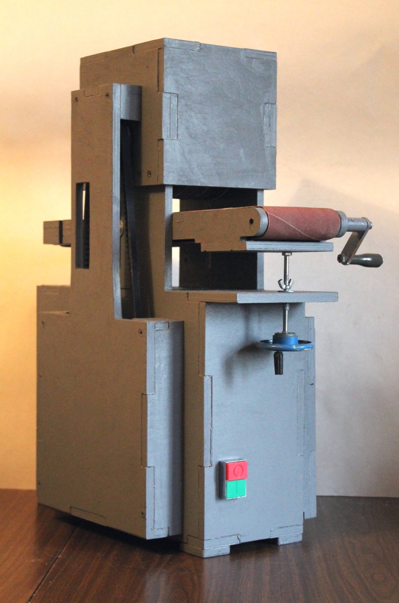
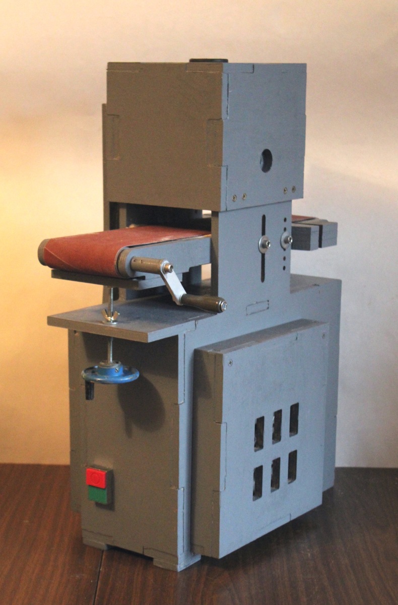
Machine Specifications
At the output we have the following characteristics:
- dimensions (LxWxH) 470x240x580 mm
- weight 8.5 kg
- speed of movement of grinding grinding 20 m / s
- drum diameter 120 mm, drum speed around - 2800 rpm.
- manual submission of the workpiece (with the possibility of completion before automatic submission)
- 80 mm maximum workpiece width
- workpiece height from 1 to 60 mm
- working removal (on medium hardwood, workpiece width 40 mm) 0.15 - 0.20 mm per pass
- single-phase asynchronous motor 180 Watt, 1350 rpm.
- dust removal (inlet for dust extraction hose 40 mm)
- the presence of the button "emergency engine stop"
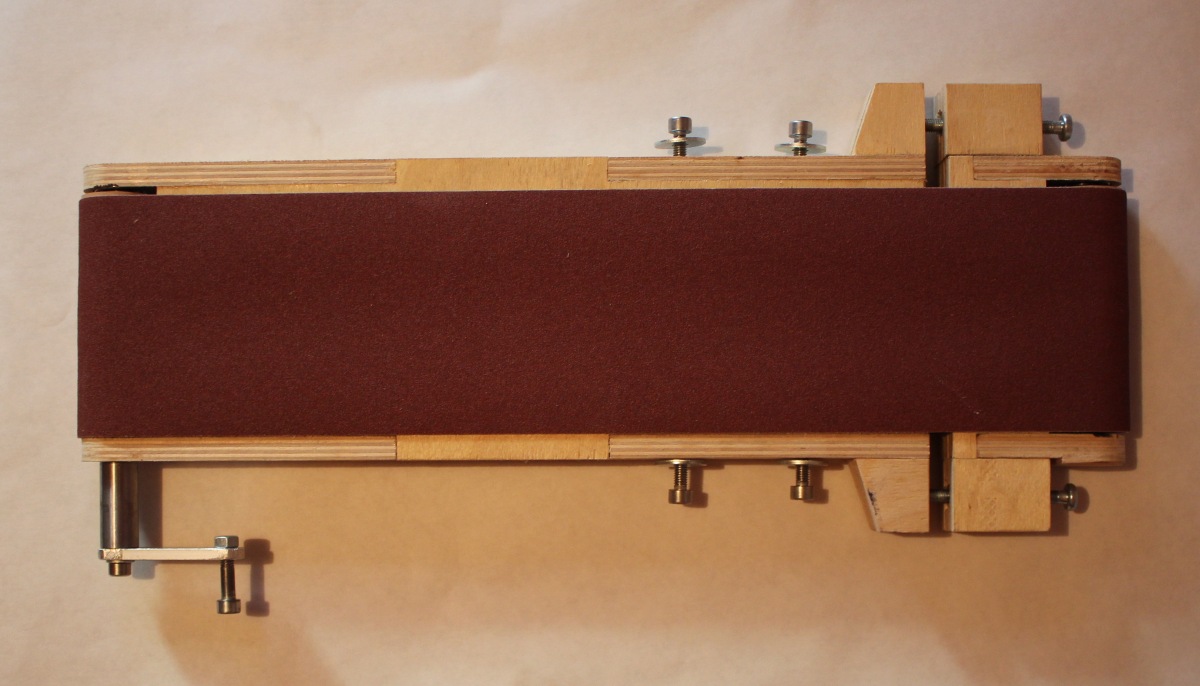
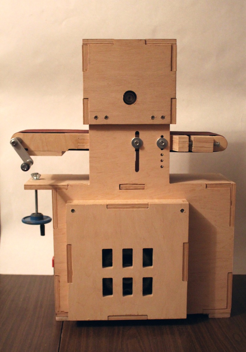
Feeding table
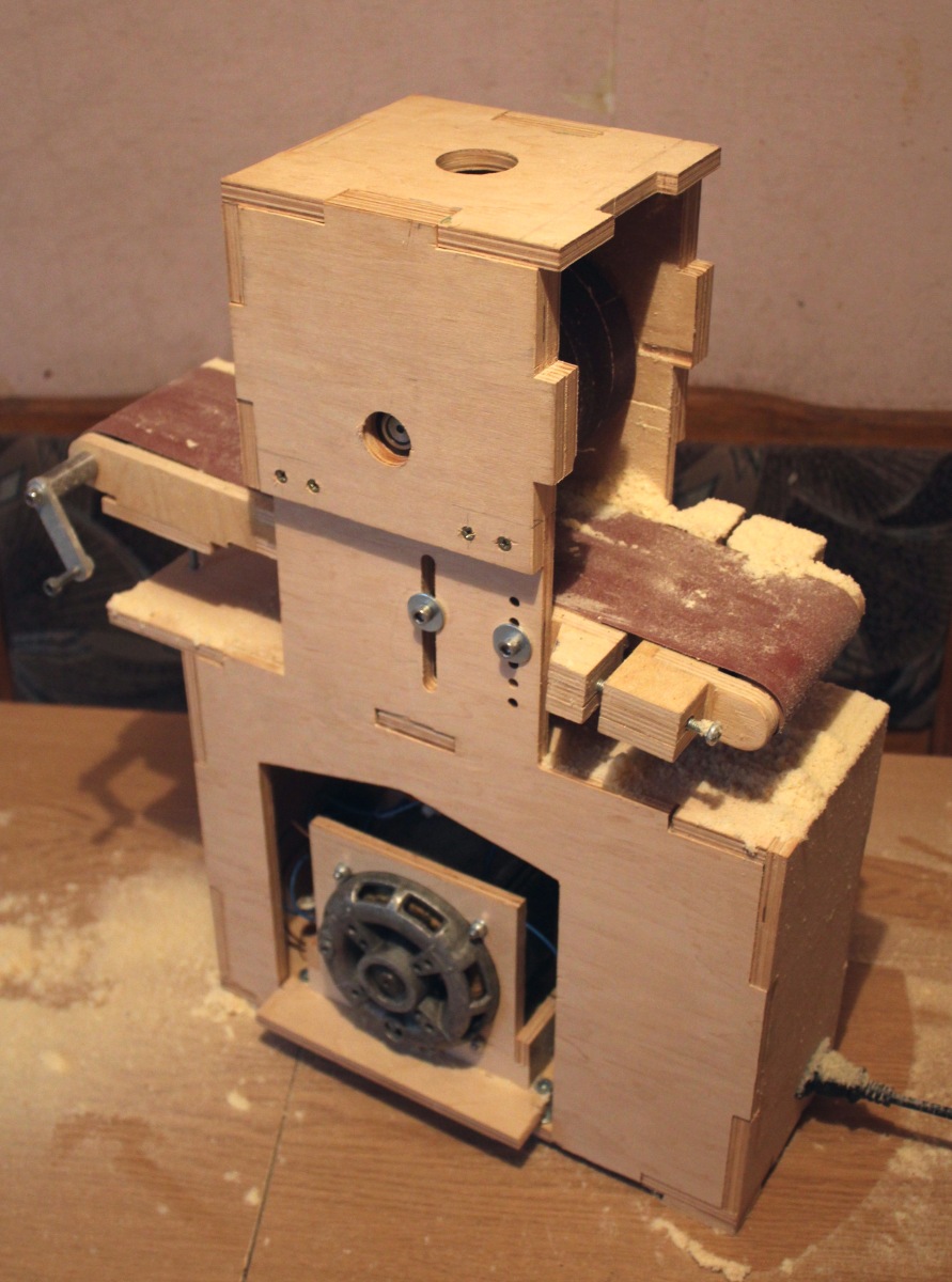
In fact - a separate project in the overall project. Worked in sufficient detail. The basis of the dimensions taken tape from woodworking grinding machines 915x100 mm. It is possible to put the motor auto feed or, by extending fasteners, make a separate belt grinding machine. Rollers rubberized, ordered them separately. The position of the tape is adjustable, to give the rollers barreling wound electrical tape in the center.
The feed table is fixed on two M6 screws, and two more screws allow you to firmly fix the table in the desired position.
Those. The processing cycle is the following: the handwheel set the required size, fixed the table with screws, ground the workpiece, unfastened the table.


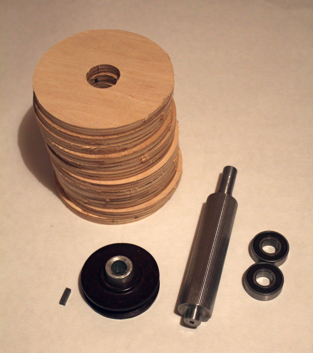
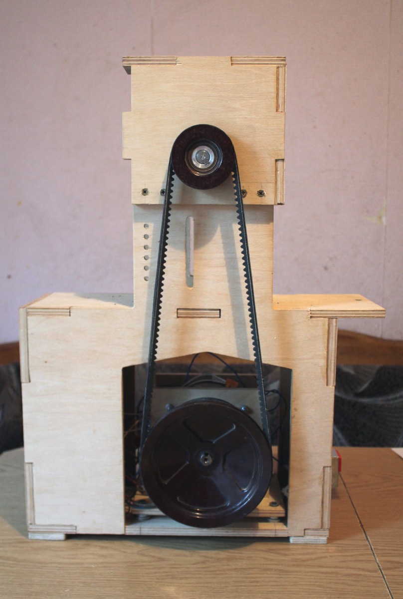
Grinding drum
It is assembled separately from the case, attached to it with eight screws. The drum is not removable (relative to its body), the replacement of the tape is implemented. Shliflenta fastens on a drum surface by means of a bilateral adhesive tape, the ends are beaten with brackets (the stapler).
Assembling the drum: on the shaft stuck with epoxy sponge plywood rings. After a manual router, he gave the drum a cylindrical shape (with the machine engine turned on). Spied this reception from the Americans (Canadians?).
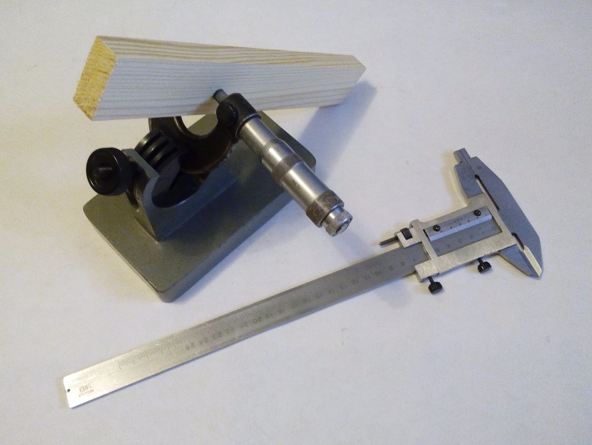
After the final assembly and adjustment of the surface of the drum turned parallel to the feed table.


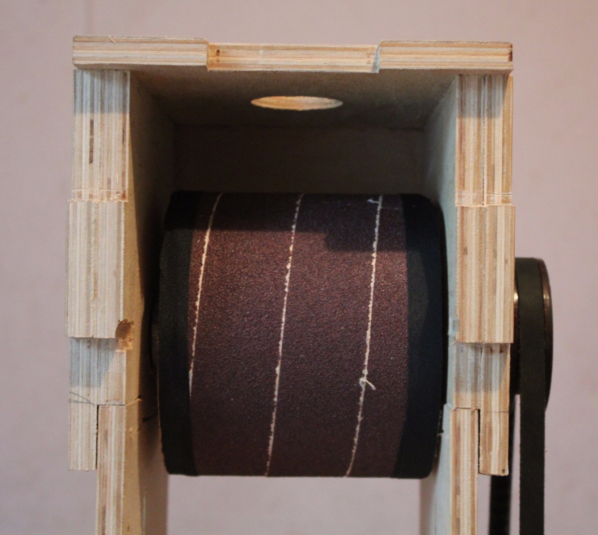
Housing assembly
The basis of the body is 10 mm plywood. Gluing - on the PVA (D2). Inside mounted electrician and engine. The protective covers on the engine and the belt transmission were drawn after assembling everything together, in place — I didn’t want to calculate the dimensions in advance. Painted all water-based paint (it can paint the surface in a residential area).
Separately, I want to focus on handles, handwheels, handwheels, limbs and other controls - they are very important and without them the convenience of work falls dramatically.

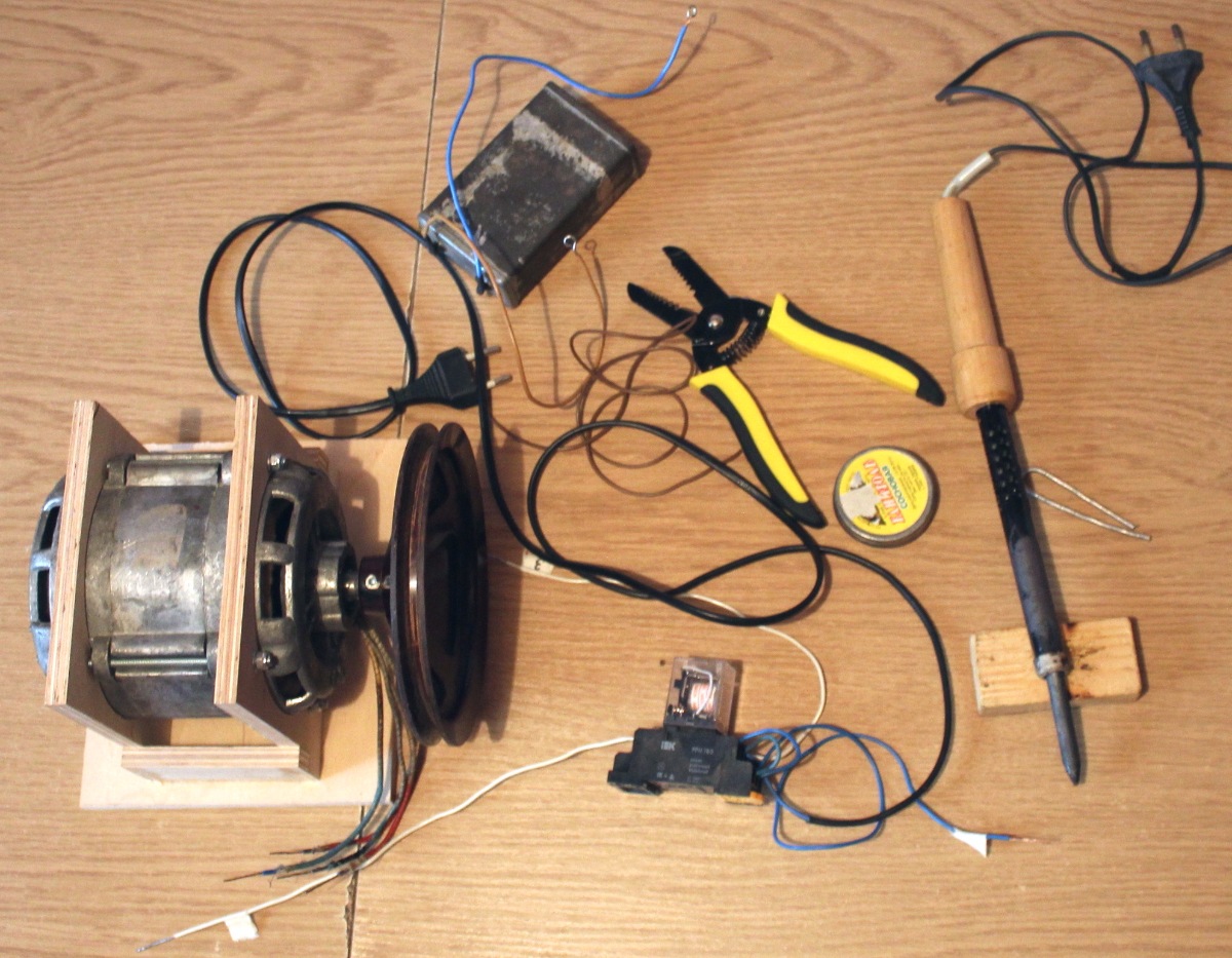
Electrician
I bring the electrical circuit, in fact, it consists of two parts: the start of an induction motor from a capacitor and the classic implementation of the Start / Stop book through a magnetic starter. True, I replaced the magnetic starter with an electromechanical relay (the starter seemed to me too big and clicking loudly).
The connection to the 220 Volt network is realized through the IEC connector (as in power units in stationary computers, for example). This allows you to unplug the cord when not needed. The extra wires do not hang out under your feet, they can be stored separately, change the required length, etc.


Results, measurements
The machine as a whole turned out, the tasks entrusted to it can easily perform. Accuracy of processing is sufficient (for these tasks, for wood).
Dust removal works well, only large pieces of lumpy dust fall out of the machine (after turning off the hood). The finest and most harmful dust goes straight to the chip breaker.
Advantages of the design
- low machine weight (relative to the size of the workpiece)
- fast reconfiguration to the desired size
- convenient adjustment of the removal thickness per pass
- acceptable machining accuracy (accuracy of 0.05 mm over a length of 200 mm)
- submission of the workpiece is carried out by rotating the handle (no need to push the pusher, it is possible to finish the automatic feed in the future)
- maintainability, it is possible to replace / improve individual elements (engine, grinding drum) without making fundamental changes in the layout.
Design flaws
- auto feed not implemented
- no clamping of the workpiece to the table (to the transport tape)
- engine power is not enough for coarse grinding
- the maximum width of the workpiece is small
- Long-term replacement of the sanding belt, no function for quick removal / installation of the drum
Criticism and suggestions
Criticism, comments and suggestions as a whole and for individual elements are welcome. Welcome to the comments.
All Articles