PC Search-2. The second birthday
This article describes how the replica Poisk-2 micro-computer designed by the ELEKTRONMASH Kiev plant in the early 90s was designed and manufactured.
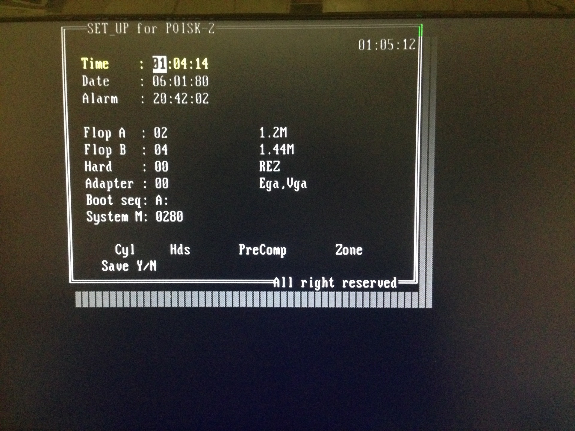
As a child I became the proud owner of the Poisk-2 computer. In this analogue XT-shki was used the domestic 8086th KR1810VM86M processor at 8 MHz. Of the features, you can highlight a clock with a battery on the “board” and the BIOS, which you can switch to when you turn it on by pressing DEL.
The BIOS allowed the computer to work with 1.2Mb and 1.44Mb drives, set the current time and settings for the MFM-hard drive (by selecting one of several pre-prepared options).
And there was a place on the board with 2 megabytes of RAM. The second megabyte was used as EMS. Memory chips were KR565RU7I (K) and KR565RU5. Judging by the documentation, there were four computer configurations: 640KB of RAM, 2MB of RAM, and the same two options with the KM1810VM87 coprocessor delivered. In practice, however, there were often boards with 1MB of RAM.
My computer had 640KB of RAM, a 5-inch floppy disk drive for working with 720KB floppy disks and a Hercules video card, which significantly narrowed the range of games launched. Despite these limitations, I continued to comprehend the computer wisdom with great interest.
It's no secret that there are people who are passionate about antiques. And now there are entire communities of collectors of antique computers. Occasionally I remembered my “Search-2” warmly: the rumble of the drive and the black-and-white picture on the monitor. Since those distant times, only the keyboard and a stack of 5.25 "GMD-130 floppy disks have remained. that finding it in 2015 is no longer so easy - the few instances that came across turned out to be unsuitable for work. There were several reasons for this: firstly, the main problem of domestic electronics was expensive parts that people loved very much . Vykushivat and pass on drag.metally "Search 2" is not an exception - on the motherboard has a huge amount of KM-app (such green capacitors), and 8 more slots the ISA-8 with gold plated contacts.
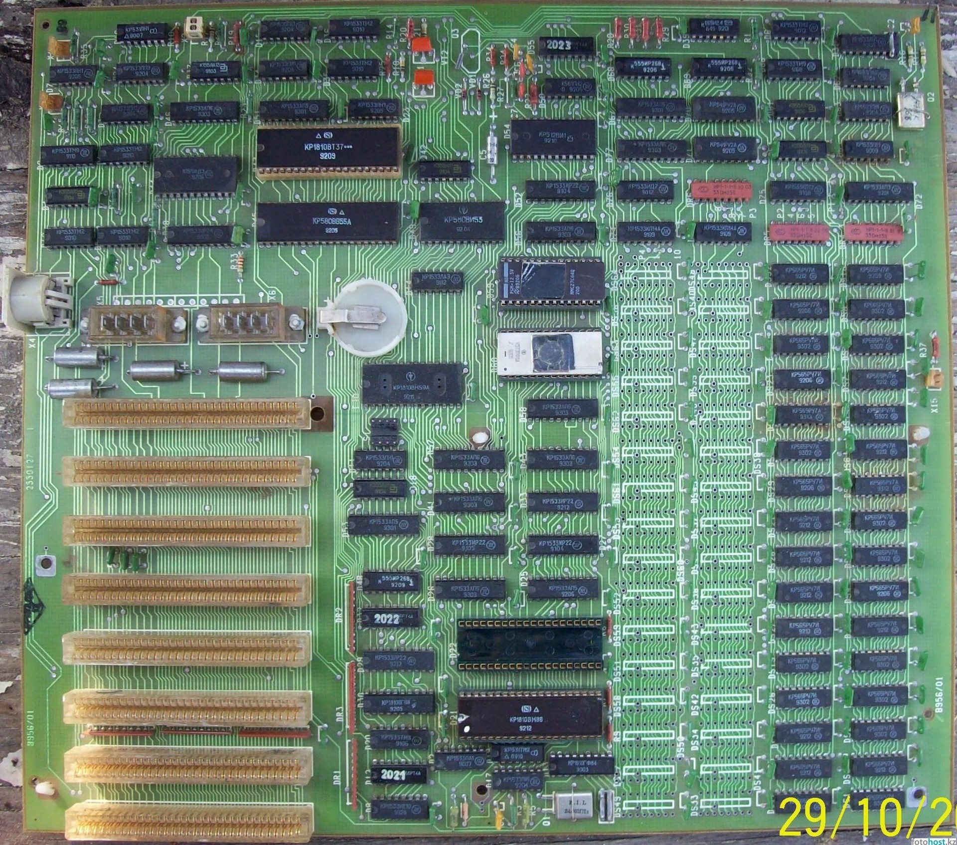
Secondly, the quality of the motherboard itself left much to be desired. Their repair, according to experts, was accompanied by flaking tracks. The chances of getting a worker "Search-2" are rapidly melting.
But the metastases of nostalgia really took their roots very deeply and demanded not to give up the dream! And I succumbed to their influence. So, I faced a task, with the likeness of which I had never encountered before: being far from circuit engineering and installation, I wanted to somehow assemble this computer. Having estimated all the chances out of ignorance (now I’m looking at this idea differently), I came to the conclusion that one could try to make a new high-quality printed circuit board and build “Search-2” on its basis.
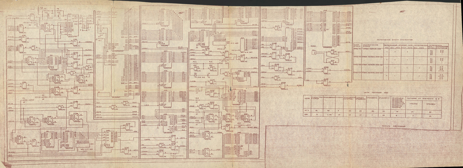
One of the driving forces was several computer concept options found in the depths of the network. Having carefully compared them, I chose one that seemed to me the most complete. Fragment of the scheme:
The case remained for the "small" - it was necessary to determine the instument and master it! I read a lot of reviews and opinions and stopped at Altium Designer. Decided to act in the following sequence:
- first draw a diagram and try to part the tracks
- then, if I still get to some result in the draft scheme, look for opportunities to get the necessary components. At the forums, experts assured that there are details everywhere, even a dime a dozen, but who knows ...
- if the parts are really easy to get, find a suitable manufacturer to order one or several test copies of the board
- while the board is made, buy components
- installation and start.
Well, back to the “Altium Designer”. The design process required a serious approach. Initially, the editor does not know anything about the components that will be used - you need to add all their parameters to the library. In the process of “drawing,” it turned out that the power pins on the chips in such editors are usually “in mind” and are not indicated on the diagrams. This led to a library revision and reconciliation with specifications. Step by step, I added new elements, arranged and connected them in the diagram:

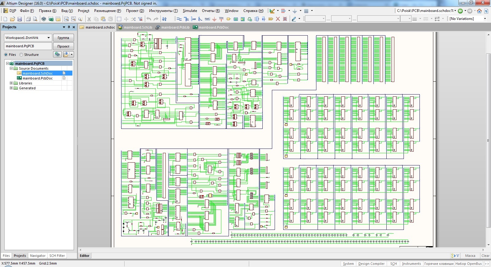
And finally, the last contact is connected, and the scheme is thoroughly verified with the original. It's time to put all the components on the virtual board, and it turned out to be rather difficult. The fact is that I did not have a single original on my hands so that I could somehow measure the distances from the edges and between the components. A lot of photos of the board found on forums and websites came to the rescue. Some of them turned out to be quite detailed: one could see not only the marking of the chips, but also the coordinate grid.
Thanks to this very grid, I began to arrange the components. All of them were of course domestic, with a metric step between the conclusions. In our chips, this step is equal to 2.5 mm (as opposed to imported ones - 2.54 mm). And in the step was placed two divisions of the coordinate grid. Thus, one division was 1.25 mm.
Having missed a few nights behind this case, I became thoughtful - something did not converge. In some places, the relative position of the components stubbornly did not want to match the original. After studying the photos of the board, it turned out that there is some kind of suspicious transition in the grid near the ISA slots. I immediately guessed: ISA-slots are made in accordance with the international standard, and the grid for them differs from the metric one. After adjusting the size of the overall picture finally began to look like the original.

The long-awaited moment has come - I will be able to try out the magic of automatic routing! And after several attempts with different settings, I had a double impression: auto-authoring is cool, but I cannot use it ... Altium Designer carefully looked for possible ways to connect the contacts, drawing intricate patterns, but the design was very far from the original:

Above, I mentioned that I do not understand the intricacies of electronics, and I could not even evaluate the correctness of automatic routing. I had to pave the tracks manually, focusing on the existing photos. And everything would be fine if it were not for the blurred and illuminated areas in the photo. It was like a kind of puzzle, in which the layout in some places had to be done by eliminating unacceptable options that in one way or another interfere with making well-visible tracks. A month has passed, and one evening I was surprised to find that all the tracks on the board are divorced, with the exception of a couple of contacts.
I was very pleased with the fact that the tracks coincided with the photos of the original, which means that the scheme by which I started to do the project turned out to be correct. There remained a few contacts that simply could not be connected - the tracks did not leave the photo from them, and there was no place where they could be laid. The decision was suggested by one of the owners of the original: the contacts were supposedly connected by one of the inner layers, since they were “called” by a multimeter. Without thinking, I embodied these assumptions in my project. Now he was ready.
Surprisingly, I still completed the first paragraph of my plan. It is time to find out if it will be difficult to get the necessary components for assembling a computer. Even earlier, in the process of “drawing,” I was looking for potential places where to get one or other details. For the most part, there was no shortage of parts on the market. Almost any of them can be found, if not on the local radio market, then in various online stores.
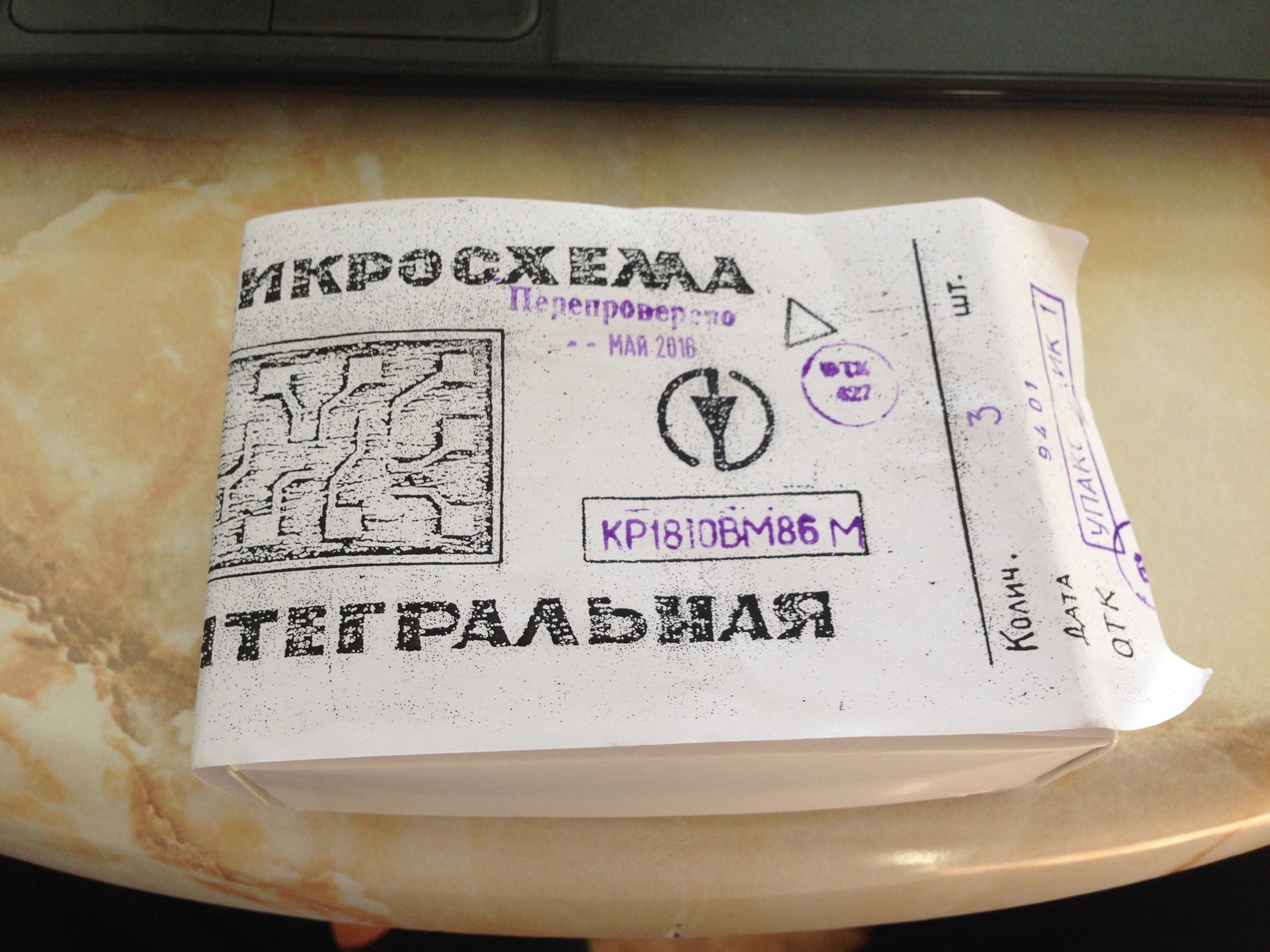
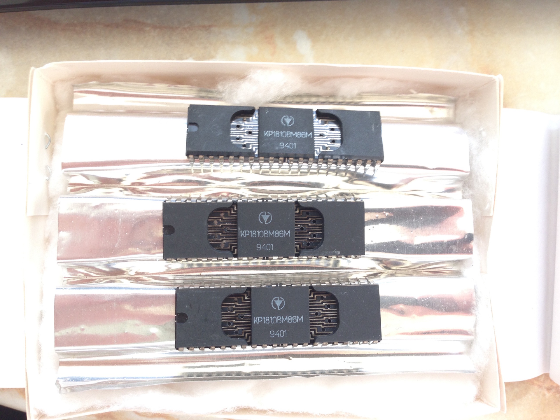
Special attention should be paid to the original processors (they should be used in Search 2), which I purchased in the amount of 3 pieces. (just in case) from the manufacturer Kvazar-IS:

It became clear that the main task remains to determine the manufacturer of test copies of the board. Having studied a number of Chinese firms, I settled on one. She allowed to make at least five copies of the boards. To try all the options, I decided to go for domestic producers. And one of them offered me to make a board in a single copy.
Considering that there could be errors on the board, I agreed to this proposal. In addition, this order cost me much cheaper compared to the Chinese.
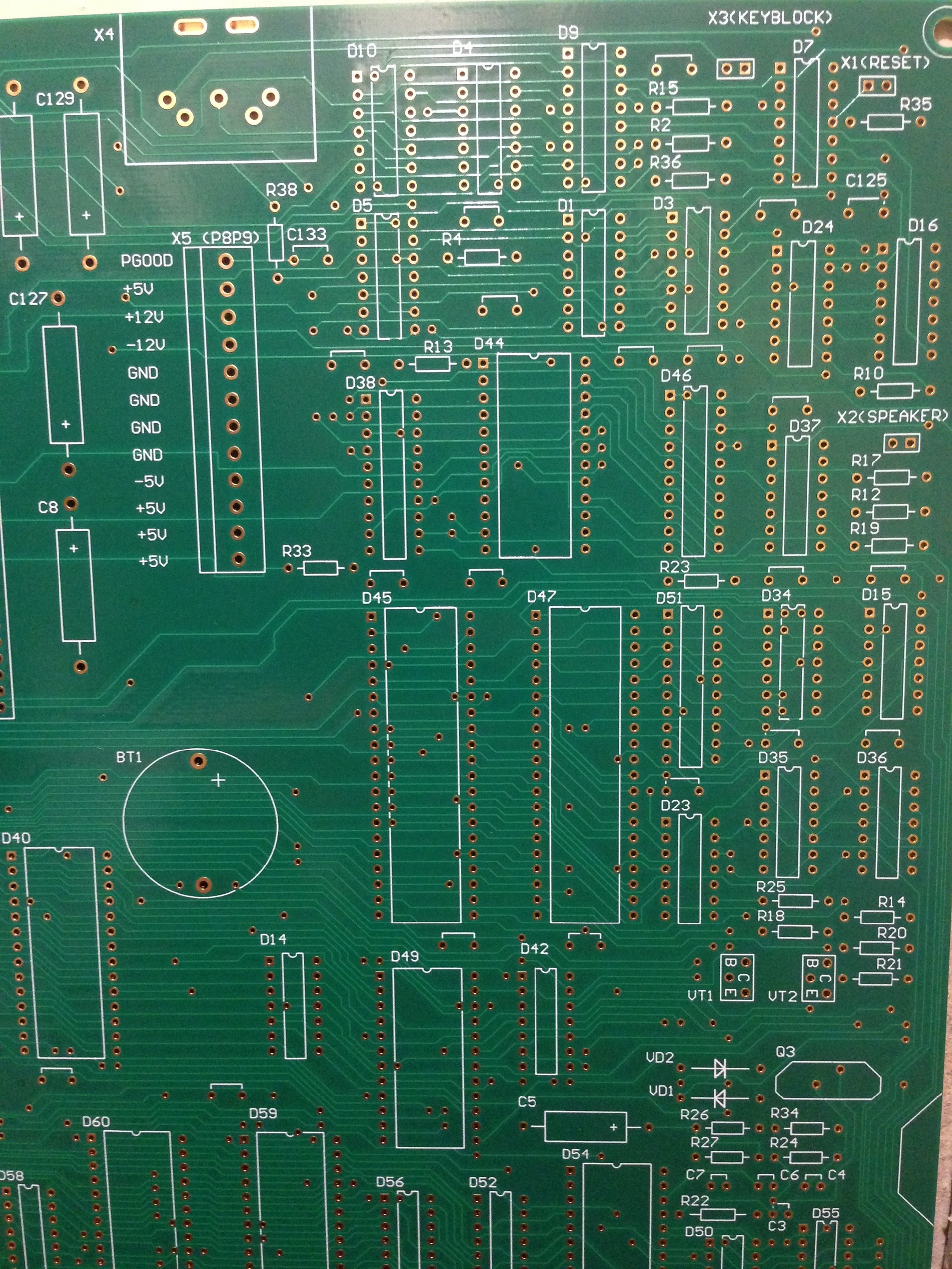
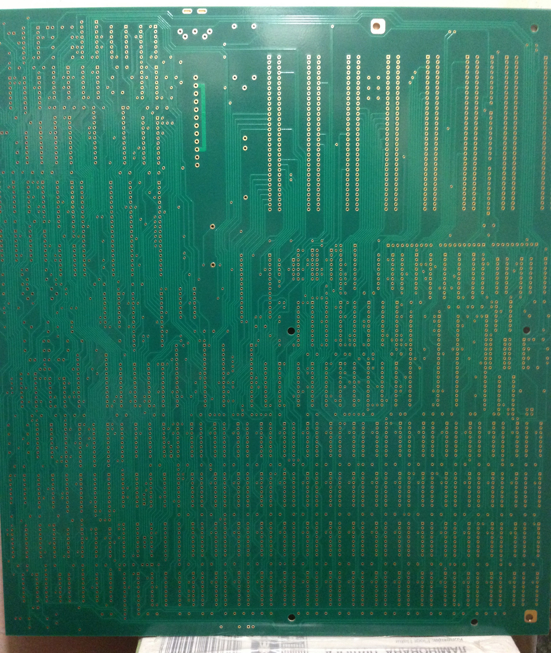
A trial copy was launched into production, and there was no way back: I began to look for the necessary details. It is worth noting that the marks of the components on the scheme were slightly different from those used in practice (the majority of logic chips on the circuit were the 555th series, while all the photos showed the 1533rd). I decided that the chipset should match the set of photos as much as possible. A little more time passed, and a new board came to me:
Now everything I needed was in my hands. It remained to install the components on the board. I had the sense not to build it myself, although initially the set seemed to be such a designer who soldered, and if all the parts are good, it will work. On one of the thematic sites, I met a man who took on this task with great enthusiasm, because it was the first replica of Search 2.
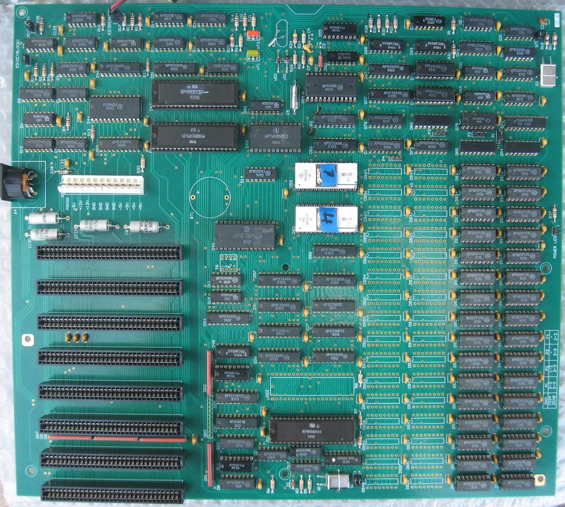
After several days of work, the parts were in place, and the board now looked like this:
The long-awaited moment of launch has come, and ... alas, nothing worked. It was then that I understood how difficult it was to find faults in such a complex complex. The master had to carefully study the work of all the nodes; in the course of the work, he replaced one chip and a crystal oscillator, as well as a pair of capacitors, the nominal value of which I determined incorrectly.
Of course, I didn’t go without errors in the scheme (in some places I managed to mix up the power supply with the “ground”), and if I dared to carry out the installation and launch myself, then this venture would never have been crowned with success.
But thanks to the professionalism of the master after a week of hard work, a clicking test of RAM finally appeared on the screen. For me, this was also a small victory - yes, errors in the project were not fatal, and on the whole, everything was right!
It remained to make a couple of minor improvements in the project.
First, it was necessary to slightly adjust the location of the mounting holes. Still, it was not possible to perfectly comply with all the sizes of the photographs.
And secondly, the problem with the places for large circuits. We decided to install them on the panels, and now practically all sold panels have an inch pitch. There is a need to fix the places for DIP40, DIP28 and DIP24 microcircuits.

Simultaneously with the adjustments of the project, specialized topics were created to study the demand for this computer. I suspected that it must necessarily cause interest, since there were very few copies left in working order, and no one had yet produced a “remake” of this computer. Attractive in the “Search-2” is that it is actually a compatible IBM-PC XT computer, which out of the box supports high density drives (1.2 MB and 1.44 MB), and thanks to standard ISA-8 slots it is easily expanded by import controllers. . You can install the NEC V30 processor in it, which slightly speeds up its work, and the 8087 coprocessor. Perhaps this will seem ridiculous to the modern reader, but there are enough people who want to get just such an “ancient” computer and bring it to perfection in its class.
By the way, now VGA-video card, port and drive controller, XT-IDE controller to which the IDE-HDD is connected, and SoundBlaster Pro sound card successfully work with the test instance. In the early 90s, for me, possession of such a set was simply beyond dreams:

My expectations about the demand were more than justified, and 40 printed circuit boards for Poisk-2 PC have already been manufactured and distributed.
All project materials are available at this address .
And at the end of the article I want to demonstrate the operation of the computer and some tests - where without it!
The following components were used for the demonstration:
First meeting
As a child I became the proud owner of the Poisk-2 computer. In this analogue XT-shki was used the domestic 8086th KR1810VM86M processor at 8 MHz. Of the features, you can highlight a clock with a battery on the “board” and the BIOS, which you can switch to when you turn it on by pressing DEL.
The BIOS allowed the computer to work with 1.2Mb and 1.44Mb drives, set the current time and settings for the MFM-hard drive (by selecting one of several pre-prepared options).
And there was a place on the board with 2 megabytes of RAM. The second megabyte was used as EMS. Memory chips were KR565RU7I (K) and KR565RU5. Judging by the documentation, there were four computer configurations: 640KB of RAM, 2MB of RAM, and the same two options with the KM1810VM87 coprocessor delivered. In practice, however, there were often boards with 1MB of RAM.
My computer had 640KB of RAM, a 5-inch floppy disk drive for working with 720KB floppy disks and a Hercules video card, which significantly narrowed the range of games launched. Despite these limitations, I continued to comprehend the computer wisdom with great interest.
Back to the past
It's no secret that there are people who are passionate about antiques. And now there are entire communities of collectors of antique computers. Occasionally I remembered my “Search-2” warmly: the rumble of the drive and the black-and-white picture on the monitor. Since those distant times, only the keyboard and a stack of 5.25 "GMD-130 floppy disks have remained. that finding it in 2015 is no longer so easy - the few instances that came across turned out to be unsuitable for work. There were several reasons for this: firstly, the main problem of domestic electronics was expensive parts that people loved very much . Vykushivat and pass on drag.metally "Search 2" is not an exception - on the motherboard has a huge amount of KM-app (such green capacitors), and 8 more slots the ISA-8 with gold plated contacts.
Secondly, the quality of the motherboard itself left much to be desired. Their repair, according to experts, was accompanied by flaking tracks. The chances of getting a worker "Search-2" are rapidly melting.
If the mountain does not go to Mohammed ...
But the metastases of nostalgia really took their roots very deeply and demanded not to give up the dream! And I succumbed to their influence. So, I faced a task, with the likeness of which I had never encountered before: being far from circuit engineering and installation, I wanted to somehow assemble this computer. Having estimated all the chances out of ignorance (now I’m looking at this idea differently), I came to the conclusion that one could try to make a new high-quality printed circuit board and build “Search-2” on its basis.
One of the driving forces was several computer concept options found in the depths of the network. Having carefully compared them, I chose one that seemed to me the most complete. Fragment of the scheme:
The case remained for the "small" - it was necessary to determine the instument and master it! I read a lot of reviews and opinions and stopped at Altium Designer. Decided to act in the following sequence:
- first draw a diagram and try to part the tracks
- then, if I still get to some result in the draft scheme, look for opportunities to get the necessary components. At the forums, experts assured that there are details everywhere, even a dime a dozen, but who knows ...
- if the parts are really easy to get, find a suitable manufacturer to order one or several test copies of the board
- while the board is made, buy components
- installation and start.
Through thorns to the project
Well, back to the “Altium Designer”. The design process required a serious approach. Initially, the editor does not know anything about the components that will be used - you need to add all their parameters to the library. In the process of “drawing,” it turned out that the power pins on the chips in such editors are usually “in mind” and are not indicated on the diagrams. This led to a library revision and reconciliation with specifications. Step by step, I added new elements, arranged and connected them in the diagram:
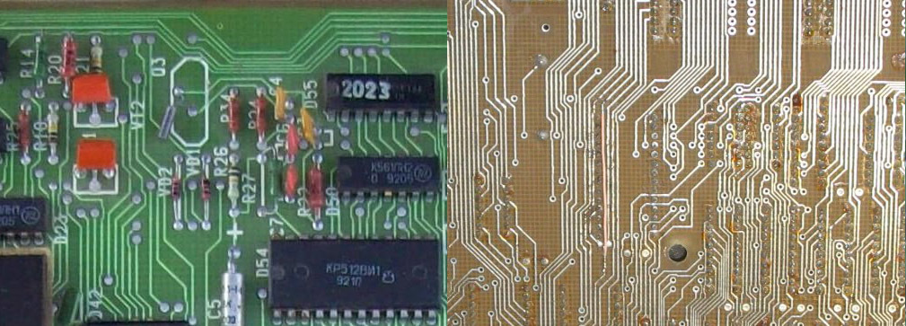
And finally, the last contact is connected, and the scheme is thoroughly verified with the original. It's time to put all the components on the virtual board, and it turned out to be rather difficult. The fact is that I did not have a single original on my hands so that I could somehow measure the distances from the edges and between the components. A lot of photos of the board found on forums and websites came to the rescue. Some of them turned out to be quite detailed: one could see not only the marking of the chips, but also the coordinate grid.
Thanks to this very grid, I began to arrange the components. All of them were of course domestic, with a metric step between the conclusions. In our chips, this step is equal to 2.5 mm (as opposed to imported ones - 2.54 mm). And in the step was placed two divisions of the coordinate grid. Thus, one division was 1.25 mm.
Having missed a few nights behind this case, I became thoughtful - something did not converge. In some places, the relative position of the components stubbornly did not want to match the original. After studying the photos of the board, it turned out that there is some kind of suspicious transition in the grid near the ISA slots. I immediately guessed: ISA-slots are made in accordance with the international standard, and the grid for them differs from the metric one. After adjusting the size of the overall picture finally began to look like the original.
My eyes!
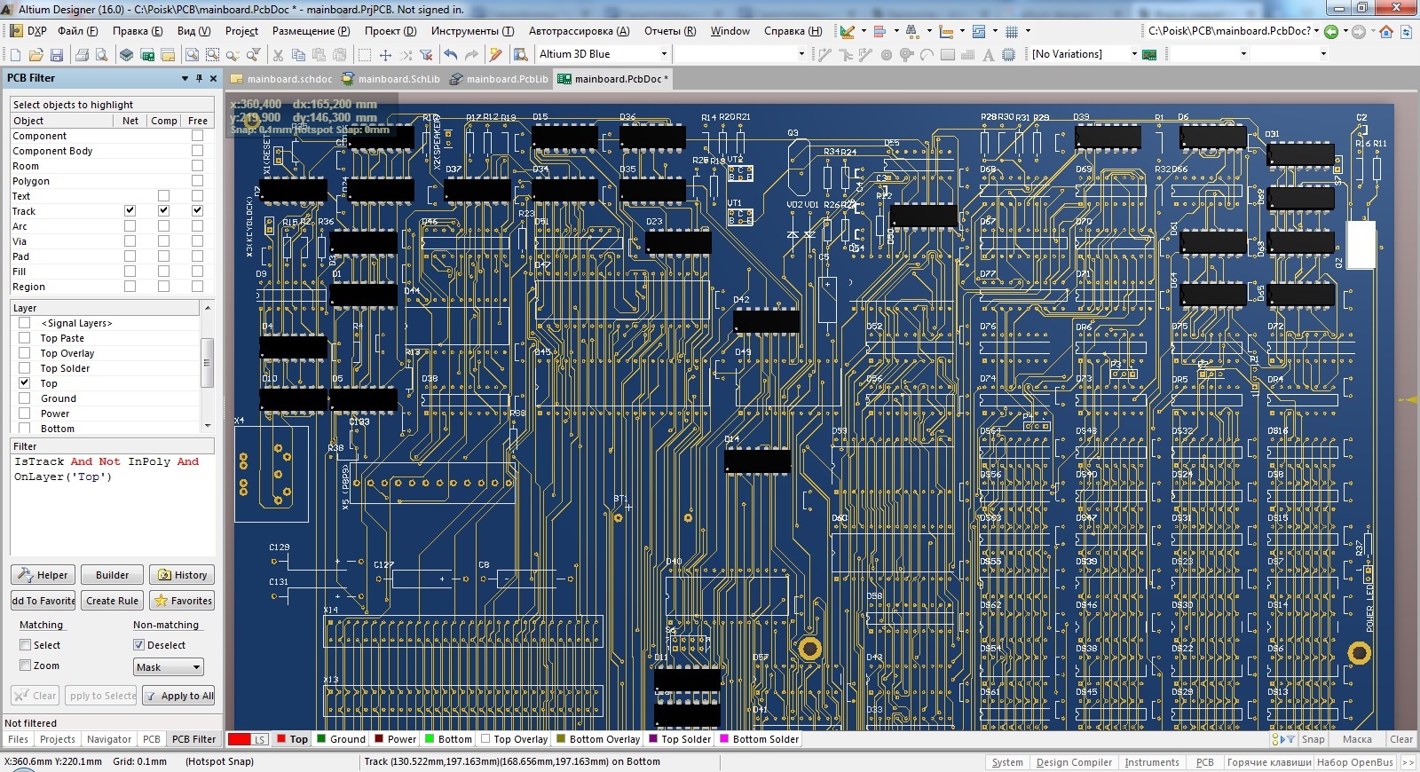
The long-awaited moment has come - I will be able to try out the magic of automatic routing! And after several attempts with different settings, I had a double impression: auto-authoring is cool, but I cannot use it ... Altium Designer carefully looked for possible ways to connect the contacts, drawing intricate patterns, but the design was very far from the original:
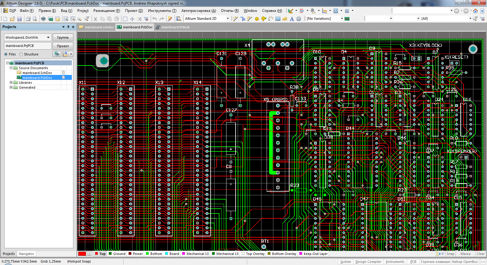
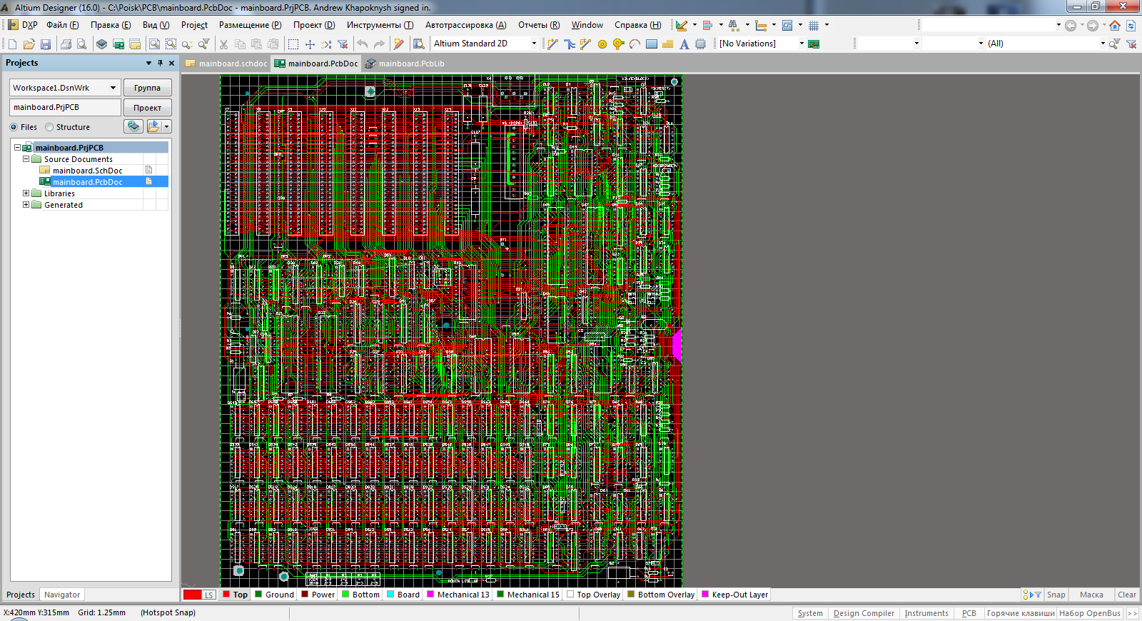
Above, I mentioned that I do not understand the intricacies of electronics, and I could not even evaluate the correctness of automatic routing. I had to pave the tracks manually, focusing on the existing photos. And everything would be fine if it were not for the blurred and illuminated areas in the photo. It was like a kind of puzzle, in which the layout in some places had to be done by eliminating unacceptable options that in one way or another interfere with making well-visible tracks. A month has passed, and one evening I was surprised to find that all the tracks on the board are divorced, with the exception of a couple of contacts.
I was very pleased with the fact that the tracks coincided with the photos of the original, which means that the scheme by which I started to do the project turned out to be correct. There remained a few contacts that simply could not be connected - the tracks did not leave the photo from them, and there was no place where they could be laid. The decision was suggested by one of the owners of the original: the contacts were supposedly connected by one of the inner layers, since they were “called” by a multimeter. Without thinking, I embodied these assumptions in my project. Now he was ready.
First go!
Surprisingly, I still completed the first paragraph of my plan. It is time to find out if it will be difficult to get the necessary components for assembling a computer. Even earlier, in the process of “drawing,” I was looking for potential places where to get one or other details. For the most part, there was no shortage of parts on the market. Almost any of them can be found, if not on the local radio market, then in various online stores.
Special attention should be paid to the original processors (they should be used in Search 2), which I purchased in the amount of 3 pieces. (just in case) from the manufacturer Kvazar-IS:
It became clear that the main task remains to determine the manufacturer of test copies of the board. Having studied a number of Chinese firms, I settled on one. She allowed to make at least five copies of the boards. To try all the options, I decided to go for domestic producers. And one of them offered me to make a board in a single copy.
Considering that there could be errors on the board, I agreed to this proposal. In addition, this order cost me much cheaper compared to the Chinese.
A trial copy was launched into production, and there was no way back: I began to look for the necessary details. It is worth noting that the marks of the components on the scheme were slightly different from those used in practice (the majority of logic chips on the circuit were the 555th series, while all the photos showed the 1533rd). I decided that the chipset should match the set of photos as much as possible. A little more time passed, and a new board came to me:
Last item plan
Now everything I needed was in my hands. It remained to install the components on the board. I had the sense not to build it myself, although initially the set seemed to be such a designer who soldered, and if all the parts are good, it will work. On one of the thematic sites, I met a man who took on this task with great enthusiasm, because it was the first replica of Search 2.
After several days of work, the parts were in place, and the board now looked like this:
The long-awaited moment of launch has come, and ... alas, nothing worked. It was then that I understood how difficult it was to find faults in such a complex complex. The master had to carefully study the work of all the nodes; in the course of the work, he replaced one chip and a crystal oscillator, as well as a pair of capacitors, the nominal value of which I determined incorrectly.
Of course, I didn’t go without errors in the scheme (in some places I managed to mix up the power supply with the “ground”), and if I dared to carry out the installation and launch myself, then this venture would never have been crowned with success.
But thanks to the professionalism of the master after a week of hard work, a clicking test of RAM finally appeared on the screen. For me, this was also a small victory - yes, errors in the project were not fatal, and on the whole, everything was right!
It remained to make a couple of minor improvements in the project.
First, it was necessary to slightly adjust the location of the mounting holes. Still, it was not possible to perfectly comply with all the sizes of the photographs.
And secondly, the problem with the places for large circuits. We decided to install them on the panels, and now practically all sold panels have an inch pitch. There is a need to fix the places for DIP40, DIP28 and DIP24 microcircuits.
"Search" - to the masses!
Simultaneously with the adjustments of the project, specialized topics were created to study the demand for this computer. I suspected that it must necessarily cause interest, since there were very few copies left in working order, and no one had yet produced a “remake” of this computer. Attractive in the “Search-2” is that it is actually a compatible IBM-PC XT computer, which out of the box supports high density drives (1.2 MB and 1.44 MB), and thanks to standard ISA-8 slots it is easily expanded by import controllers. . You can install the NEC V30 processor in it, which slightly speeds up its work, and the 8087 coprocessor. Perhaps this will seem ridiculous to the modern reader, but there are enough people who want to get just such an “ancient” computer and bring it to perfection in its class.
By the way, now VGA-video card, port and drive controller, XT-IDE controller to which the IDE-HDD is connected, and SoundBlaster Pro sound card successfully work with the test instance. In the early 90s, for me, possession of such a set was simply beyond dreams:
My expectations about the demand were more than justified, and 40 printed circuit boards for Poisk-2 PC have already been manufactured and distributed.
All project materials are available at this address .
Work and Testing
And at the end of the article I want to demonstrate the operation of the computer and some tests - where without it!
The following components were used for the demonstration:
The processor - NEC V30 D70116D -10
Video Card - Realtek PT-505S 256Kb
ISA Floppy and Serial Controller (Sergey Kiselev) + FDD 3.5 "1.44Mb + FDD 5.25" 1.2Mb
HDD - XT-IDE v2.0 (Sergey Kiselev) + WD Caviar 3.2Gb
Sound - Aztec NX Pro (SoundBlaster Pro)
All Articles