Aerobatic flight. How to make a barrel
What does a fighter have in common with a container for storing liquid and a Goldberg machine? It would seem only that the aircraft and the barrel may be parts of a useless, but fascinating mechanism, but no. The figure of aerobatic keg combines all these things and not only.
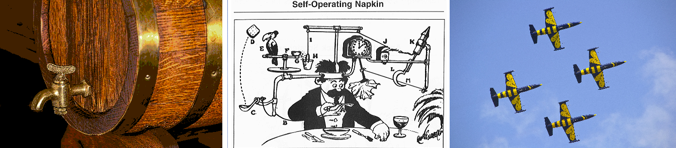
Running a barrel does not help a civilian plane to take its passengers to their destination or a fighter in battle, but it requires, if properly executed, to use all aircraft controls: ailerons, elevator and rudder.
This publication describes the process of turning the plane 360 degrees around the longitudinal axis without a reduction from the point of view of such science as flight dynamics, and describes how you can make your plane make a barrel correctly.
After the completion of the active phase of the next project, my colleague in unmanned activity raised the question of what to do until new projects took up all their free time. In response to a question posed to emptiness, we received a very specific answer “make a barrel ( do a barrel roll )”. And the truth is: the barrel of Goldberg's aircraft in aviation, at the same time complex, practically (in aerial combat), is an aerobatic figure that brings only aesthetic pleasure. So why not teach your model aircraft to make a barrel in automatic mode, even Google does it.
Before starting the practical implementation, we decided to study this process using computer models, and this is what came of it.
First, a little about why airplanes fly and how the position of the aircraft is described relative to the field of aggression. The plane holds a lift in the air, let's call it Y, which is created on the wing, but what a thing, this force appears only when the wing is blown by the oncoming air flow, respectively, you need to accelerate the plane. You can, of course, “run away from the cliff, run away”, spend some of the potential energy of the field of the earth to accelerate and even hang for a moment, but aerodynamic resistance arises indissolubly with the lifting force, let's call this force X, which the plane will brake, and the lifting force will fall, and with it we. We will fall under the action of gravity G. To counteract the resistance force, all normal aircraft have an engine, it creates a thrust force P, which can be used to overcome the resistance force. The simplest kinematic model of the aircraft describes its movement as the movement of a material point in a field of earth. In horizontal flight at a constant speed, the force of gravity is balanced by the lifting force of the wing Y = G, and the force of resistance is by the force of the engine X = P.
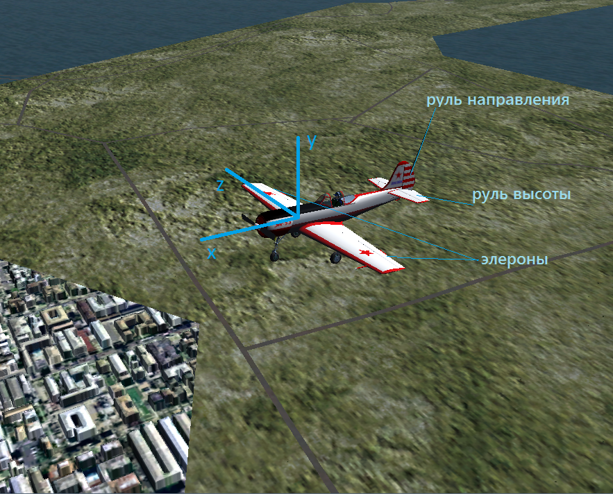
If you look at a material point under a microscope, it will turn into a material body. It is for the better: we can see the aircraft’s fuselage, wing, tail, which consists of a horizontal stabilizer and a vertical keel. The ailerons are located on the left and right wing consoles, the elevator on the horizontal tail, the elevator, and the rudder on the vertical. If all this is hard to turn, the apparatus will begin to maneuver, and the task of making the barrel will be reduced to what law will change the position of the controls to achieve the desired trajectory of the apparatus in space and relative to its own axes.
To simulate the movement of the device, we use the tools that the program provides for modeling the dynamics of aircraft with open source code JSBSim . We will entrust the output of graphs to gnuplot , and the visualization of the maneuvers of the FlightGear aircraft. We take the North American P-51 Mustang fighter as the basic dynamic model: its maneuverability will be enough to carry the barrel. For visualization, we will use a less aggressive, sporty YAK-53 aircraft.
If one imagines a “spherical”, or rather an ideal plane, in which the axes of the associated coordinate system coincide with the main axes of the inertia ellipsoid and the controls create moments each relative to only one of the axes, one can qualitatively understand how the apparatus will move when the controls deviate. Let's say the plane flies in horizontal flight; rejecting the ailerons in opposite directions, we change the magnitude of the lifting force on the wing consoles, which leads to the emergence of a moment of forces about the x axis, and the apparatus will begin to rotate around this axis. For the implementation of the barrel is just what we need. We make a script in which the ailerons are rejected for a maximum of 2.45 seconds, and then return to their original position:
The simulation results are shown in the graph:
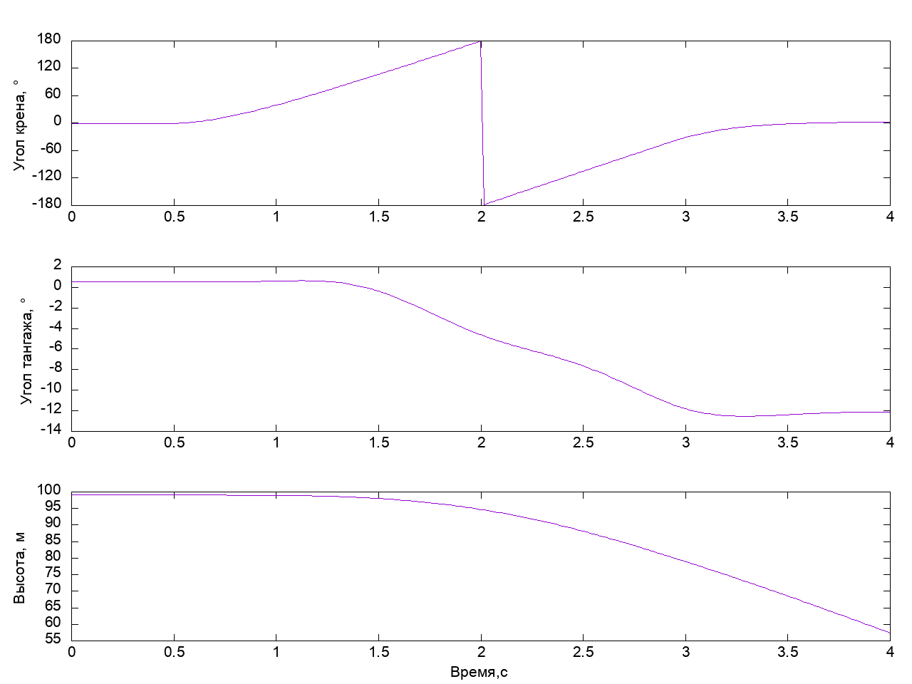
It can be seen that the plane turned 360 degrees in roll, however, it made this maneuver with a drop of 40 meters and tilted its nose by 14 degrees - this is an example of a completely unfit barrel.
And really, if you remember that an airplane from a distance is a material point, then when rotating, the projection of the lifting force on the direction of gravity decreases and the plane starts to decline, but we don’t need it at all, because we want to perform a beautiful barrel without reduction. For this, before we began to reject the ailerons, you need to create a supply of vertical velocity. We take the wheel itself - the elevator is deflected - a moment of force arises about the z axis. The nose of the plane rises, and we begin to gain height - at this moment it is time to start the rotation. Add the elevator deflection to the script by 40 percent for 0.4 seconds before the beginning of the deflection of the ailerons and return it to the neutral position. 0.2 seconds before the end of the rotation, we take the helm completely by ourselves to eliminate the lowering of the nose of the aircraft:
Look what happened:
Here it is - quite decent, fast barrel. If we returned the elevator to a neutral position a little later, the device would gain a small height and, after deflecting the ailerons, would turn into a U-turn. The combination of the “steering wheel to itself” and “deviation of the ailerons” leads to the fact that the lifting force of the wing when tilting the vehicle starts to act along the normal to the current trajectory of the vehicle and distorts it the more, the more the elevator is tilted. You can try it yourself and make sure of it.
The previous barrel was made without reduction, the pitch angle at the exit of the barrel was not much different from the original. However, the height in the process of execution was changed to 12 meters. Let's try to more actively apply controls to minimize casting in height during the execution of the figure. In order not to turn the controls of the aircraft anyhow, let's take a look at Wikipedia and see how we are recommended to make a barrel. The main idea of the perfect barrel is to keep the longitudinal axis of the aircraft in a horizontal plane. For this, the elevator and the rudder are alternately used. At the beginning of the barrel, as usual, we use the elevator to gain vertical speed. We reject the ailerons - we start the rotation. When the plane turns around the longitudinal axis, the elevator and the rudder change places. Upon reaching a roll angle of about 90 degrees, the rudder deviation will raise or lower the nose of the aircraft in a vertical plane. In this regard, we reject the rudder in order to prevent the nose from lowering. Further, when the roll angle reaches 180 degrees, it is necessary to deflect the rudder from itself in order to keep the nose of the aircraft in the horizontal plane in an inverted flight. With a further turn, we repeat the deflections of the rudder with the opposite sign at a roll angle near - 90 degrees and finish the barrel with a slight deflection of the elevator “towards ourselves”. All these steps are expressed in the script below:
Run and see what happened:
On roll, the device turned 180 degrees, while the total swing of the height change was about 2.5 m, which is five times less than in the previous case. We can say, we have got an almost perfect barrel.
So, we looked at some of the principles for performing a barrel aerobatics and made sure that, acting reasonably, we can perform a barrel of good quality on the simulator. It would be nice to move on to practice, and with the help of what we propose to do it - model aircraft + stm32f103 + mpu9250. All these elements are easily accessible and cheap, so anyone can try it themselves. The results of trial, error and instruction for repetition are the subject of the following publications.
Running a barrel does not help a civilian plane to take its passengers to their destination or a fighter in battle, but it requires, if properly executed, to use all aircraft controls: ailerons, elevator and rudder.
This publication describes the process of turning the plane 360 degrees around the longitudinal axis without a reduction from the point of view of such science as flight dynamics, and describes how you can make your plane make a barrel correctly.
Introduction
After the completion of the active phase of the next project, my colleague in unmanned activity raised the question of what to do until new projects took up all their free time. In response to a question posed to emptiness, we received a very specific answer “make a barrel ( do a barrel roll )”. And the truth is: the barrel of Goldberg's aircraft in aviation, at the same time complex, practically (in aerial combat), is an aerobatic figure that brings only aesthetic pleasure. So why not teach your model aircraft to make a barrel in automatic mode, even Google does it.
Before starting the practical implementation, we decided to study this process using computer models, and this is what came of it.
Some theory
First, a little about why airplanes fly and how the position of the aircraft is described relative to the field of aggression. The plane holds a lift in the air, let's call it Y, which is created on the wing, but what a thing, this force appears only when the wing is blown by the oncoming air flow, respectively, you need to accelerate the plane. You can, of course, “run away from the cliff, run away”, spend some of the potential energy of the field of the earth to accelerate and even hang for a moment, but aerodynamic resistance arises indissolubly with the lifting force, let's call this force X, which the plane will brake, and the lifting force will fall, and with it we. We will fall under the action of gravity G. To counteract the resistance force, all normal aircraft have an engine, it creates a thrust force P, which can be used to overcome the resistance force. The simplest kinematic model of the aircraft describes its movement as the movement of a material point in a field of earth. In horizontal flight at a constant speed, the force of gravity is balanced by the lifting force of the wing Y = G, and the force of resistance is by the force of the engine X = P.
If you look at a material point under a microscope, it will turn into a material body. It is for the better: we can see the aircraft’s fuselage, wing, tail, which consists of a horizontal stabilizer and a vertical keel. The ailerons are located on the left and right wing consoles, the elevator on the horizontal tail, the elevator, and the rudder on the vertical. If all this is hard to turn, the apparatus will begin to maneuver, and the task of making the barrel will be reduced to what law will change the position of the controls to achieve the desired trajectory of the apparatus in space and relative to its own axes.
Description of the coordinate systems used in the description of the movement of aircraft.
In the Russian / Soviet tradition, the coordinate system (SC), rigidly associated with the aircraft, is introduced as follows. The x axis is directed longitudinally in the plane of symmetry of the aircraft, from tail to nose. Perpendicular to this axis, the y axis is entered upwards. These two axes are supplemented to the right three of vectors by the z axis. It turns out that the z axis will pass along the right wing.
The motion of the apparatus in space cannot be described only with the help of a coordinate system associated with the aircraft, because we are interested in the position of the apparatus relative to the earth. For this purpose, a coordinate system is introduced, which is called the “local terrestrial coordinate system”. The X-axis of this system is in the horizontal plane and is directed to the geographical north. The axis Y is directed vertically upwards. The Z axis complements them to the right three of vectors. The location of the associated coordinate system relative to the local terrestrial system is determined by the angles of heel, pitch, and yaw. The angle between the longitudinal axis of the aircraft (in our case, the x-axis of the connected SC) and the horizontal plane XZ is called the pitch angle; it changes when the elevator is deflected. The angle between the z axis of the coupled SC and the z axis of the local earth SC, rotated so that the yaw angle is zero, is called the angle of heel, it changes when the ailerons deviate. The angle between the X axis of the local earth SC and the projection of the x axis of the connected SC onto the horizontal plane XZ is called the yaw angle, counted counterclockwise from the X axis of the local earth SC. This formalization should be sufficient for us to describe the movement of the aircraft when performing the barrel, and even if we do not use the letter designations of the axes, it is always useful to repeat the basics.
The motion of the apparatus in space cannot be described only with the help of a coordinate system associated with the aircraft, because we are interested in the position of the apparatus relative to the earth. For this purpose, a coordinate system is introduced, which is called the “local terrestrial coordinate system”. The X-axis of this system is in the horizontal plane and is directed to the geographical north. The axis Y is directed vertically upwards. The Z axis complements them to the right three of vectors. The location of the associated coordinate system relative to the local terrestrial system is determined by the angles of heel, pitch, and yaw. The angle between the longitudinal axis of the aircraft (in our case, the x-axis of the connected SC) and the horizontal plane XZ is called the pitch angle; it changes when the elevator is deflected. The angle between the z axis of the coupled SC and the z axis of the local earth SC, rotated so that the yaw angle is zero, is called the angle of heel, it changes when the ailerons deviate. The angle between the X axis of the local earth SC and the projection of the x axis of the connected SC onto the horizontal plane XZ is called the yaw angle, counted counterclockwise from the X axis of the local earth SC. This formalization should be sufficient for us to describe the movement of the aircraft when performing the barrel, and even if we do not use the letter designations of the axes, it is always useful to repeat the basics.
Tools
To simulate the movement of the device, we use the tools that the program provides for modeling the dynamics of aircraft with open source code JSBSim . We will entrust the output of graphs to gnuplot , and the visualization of the maneuvers of the FlightGear aircraft. We take the North American P-51 Mustang fighter as the basic dynamic model: its maneuverability will be enough to carry the barrel. For visualization, we will use a less aggressive, sporty YAK-53 aircraft.
Description of the process of setting up the program and output the results.
All the files needed to run the scripts are in the Github repository . To repeat the steps in this article, we need to install JSBSim , FlightGear and gnuplot . All actions will be given for the Windows operating system. Based on the instructions from here . Download and install the latest version of FlightGear from www.flightgear.org and gnuplot from www.gnuplot.info . We collect JSBSim according to the instructions . After that, we are looking for two necessary catalogs. JSBSim \ and FlightGear \ root directories. In the FlightGear \ data \ Aircraft catalog there are folders with models of airplanes: there you need to copy the model that will be used for visualization. I use the model Yak-53 , which I found on the Internet. Other models can be found here . The FlightGear \ bin directory contains the main executable file of the simulator fgfs . To visualize the dynamics, we will use the start line.
In this line, the first parameters indicate the external source of data on the dynamics of the aircraft when the simulator starts. The aircraft parameter specifies the desired model of the device. The remaining parameters are optional, their values can be found here . Useful keyboard shortcuts:
"V" -change model view
Shift + Esc - restart FlightGear with saving command line parameters
Ctrl + "R" - start recording the flight to repeat what happened.
That's all that we need in the FlightGear simulator. Let's return to the JSBSim dynamics modeling program. The JSBSim \ aircraft catalog contains dynamic aircraft models. The JSBSim \ engine catalog contains dynamic models of engines and propellers. Dynamic models of aircraft are stored in separate directories in files of the form name * .xml . At the end of each file there is a section responsible for the appearance of the output during the simulation. If we want the output to be in a form suitable for visualization in FlightGear , then it should look like this:
If we want to save data to a file, then:
It is convenient to start the modeling process using a batch file located in the root folder JSBSim \ , with the line
with content
This file deletes the previous simulation results, runs the script located at \ JSBSim \ aircraft \ p51d \ scripts \ , and then starts the drawing of the received data using gnuplot. The realtime parameter must be specified when data from JSBSim is to be received in real time, for example, when rendering in FlightGear .
Let's look at the contents of the script file:
For a proper launch, the third line indicates the model of the aircraft to be modeled and the path to the initialization file with the contents
It remains only to consider the contents of the file for plotting graphs via gnuplot :
This file generates and displays the image on the screen of three graphs: roll angle, pitch and height from time. The data for the construction is taken from the * script_name.csv file. Along the way, imperial units are converted to our usual metric ones. You can modify the file for output in PostScript , PNG or PDF formats by uncommenting the appropriate lines.
That, in general, is the whole process of preparing tools for self-modeling and displaying aircraft movement.
fgfs --native-fdm=socket,in,60,,5500,tcp --fdm=external --timeofday=noon --aircraft=Yak-53 --disable-sound --disable-real-weather-fetch --disable-clouds3d --disable-clouds
In this line, the first parameters indicate the external source of data on the dynamics of the aircraft when the simulator starts. The aircraft parameter specifies the desired model of the device. The remaining parameters are optional, their values can be found here . Useful keyboard shortcuts:
"V" -change model view
Shift + Esc - restart FlightGear with saving command line parameters
Ctrl + "R" - start recording the flight to repeat what happened.
That's all that we need in the FlightGear simulator. Let's return to the JSBSim dynamics modeling program. The JSBSim \ aircraft catalog contains dynamic aircraft models. The JSBSim \ engine catalog contains dynamic models of engines and propellers. Dynamic models of aircraft are stored in separate directories in files of the form name * .xml . At the end of each file there is a section responsible for the appearance of the output during the simulation. If we want the output to be in a form suitable for visualization in FlightGear , then it should look like this:
<output name="localhost" type="FLIGHTGEAR" port="5500" rate="60"/>
If we want to save data to a file, then:
<output name="p51d.csv" rate="60" type="CSV"> <property> velocities/vc-kts </property> <property> aero/alphadot-deg_sec </property> <property> aero/betadot-deg_sec </property> <property> fcs/throttle-cmd-norm </property> <simulation> OFF </simulation> <atmosphere> OFF </atmosphere> <massprops> OFF </massprops> <aerosurfaces> ON </aerosurfaces> <rates> ON </rates> <velocities> ON </velocities> <forces> OFF </forces> <moments> OFF </moments> <position> ON </position> <coefficients> OFF </coefficients> <ground_reactions> OFF </ground_reactions> <fcs> ON </fcs> <propulsion> OFF </propulsion> </output>
It is convenient to start the modeling process using a batch file located in the root folder JSBSim \ , with the line
JSBtest.bat *_
with content
rem Remove the old result file del /Q aircraft\p51d\Results\%1.csv rem Run the test Debug\JSBSim --script=aircraft\p51d\scripts\%1.xml --outputlogfile=aircraft\p51d\Results\%1.csv>JSBSim.out --realtime rem Generate gnuplot to the screen gnuplot aircraft\p51d\plots\%1.p
This file deletes the previous simulation results, runs the script located at \ JSBSim \ aircraft \ p51d \ scripts \ , and then starts the drawing of the received data using gnuplot. The realtime parameter must be specified when data from JSBSim is to be received in real time, for example, when rendering in FlightGear .
Let's look at the contents of the script file:
<?xml version="1.0" encoding="utf-8"?> <runscript> <use aircraft="p51d" initialize="scripts/airborne"/> <run start="0" end="5" dt="0.0166666"> <!-- --> <event name="Trims"> <condition> sim-time-sec ge 0.0 </condition> <set name="simulation/do_simple_trim" value="1"/> </event> <!-- --> <event> <condition> sim-time-sec ge 0.5 </condition> <set name="fcs/aileron-cmd-norm" value="1"/> </event> <!-- --> <event> <condition> sim-time-sec ge 2.95 </condition> <set name="fcs/aileron-cmd-norm" value="0"/> </event> </run> </runscript>
For a proper launch, the third line indicates the model of the aircraft to be modeled and the path to the initialization file with the contents
<?xml version="1.0" encoding="utf-8"?> <initialize name="airborne"> <!-- --> <running> -1 </running> <altitude unit="FT"> 325.0 </altitude> <vc unit="KTS"> 210.0 </vc> <latitude unit="DEG"> 42.3769 </latitude> <longitude unit="DEG"> -70.9993 </longitude> </initialize>
It remains only to consider the contents of the file for plotting graphs via gnuplot :
set autoscale # scale axes automatically unset log # remove any log-scaling unset label # remove any previous labels set xtic auto # set xtics automatically set ytic auto # set ytics automatically set tics font "Arial, 16" set key font "Arial, 16" set xlabel font "Arial, 16" set ylabel font "Arial, 16" # If you have graphical capabilities, you can plot on your screen # if none of the other terminals is specificed. # This is how to output the plot in PostScript format #set terminal postscript portrait enhanced color lw 1 "Helvetica" 14 size 8.5,11 # This is how to output the plot in PNG format #set terminal png size 1280,960 #set output "aircraft/p51d/results/plot.png" # This is how to output the plot in PDF format. (Not available on Mac) #set terminal pdfcairo color size 8.5,11 #set output " aircraft/p51d/results/plot.pdf" set multiplot title "" set size 1,0.30 set lmargin 10 set xrange [0:4] set ytic auto set origin 0.0,0.00 set xlabel "," set ylabel ", " plot \ "aircraft/p51d/results/trim-cruisep51d.csv" using 1:($43*0.3048) title "" with lines\ set origin 0.0,0.33 set ylabel " , °" set xlabel "" plot \ "aircraft/p51d/results/trim-cruisep51d.csv" using 1:33 title "" with lines\ set origin 0.0,0.66 set ylabel " , °" set xlabel "" set yrange [-180:180] set ytics 60 plot \ \ "aircraft/p51d/results/trim-cruisep51d.csv" using 1:32 title "" with lines\ unset multiplot # exit multiplot mode pause -1 "Press ENTER to continue"
This file generates and displays the image on the screen of three graphs: roll angle, pitch and height from time. The data for the construction is taken from the * script_name.csv file. Along the way, imperial units are converted to our usual metric ones. You can modify the file for output in PostScript , PNG or PDF formats by uncommenting the appropriate lines.
That, in general, is the whole process of preparing tools for self-modeling and displaying aircraft movement.
Simulation and results
If one imagines a “spherical”, or rather an ideal plane, in which the axes of the associated coordinate system coincide with the main axes of the inertia ellipsoid and the controls create moments each relative to only one of the axes, one can qualitatively understand how the apparatus will move when the controls deviate. Let's say the plane flies in horizontal flight; rejecting the ailerons in opposite directions, we change the magnitude of the lifting force on the wing consoles, which leads to the emergence of a moment of forces about the x axis, and the apparatus will begin to rotate around this axis. For the implementation of the barrel is just what we need. We make a script in which the ailerons are rejected for a maximum of 2.45 seconds, and then return to their original position:
The contents of the script.
<?xml version="1.0" encoding="utf-8"?> <runscript> <use aircraft="p51d" initialize="scripts/airborne"/> <run start="0" end="5" dt="0.0166666"> <!-- --> <event name="Trims"> <condition> sim-time-sec ge 0.0 </condition> <set name="simulation/do_simple_trim" value="1"/> </event> <!-- --> <event> <condition> sim-time-sec ge 0.5 </condition> <set name="fcs/aileron-cmd-norm" value="1"/> </event> <!-- --> <event> <condition> sim-time-sec ge 2.95 </condition> <set name="fcs/aileron-cmd-norm" value="0"/> </event> </run> </runscript>
The simulation results are shown in the graph:
It can be seen that the plane turned 360 degrees in roll, however, it made this maneuver with a drop of 40 meters and tilted its nose by 14 degrees - this is an example of a completely unfit barrel.
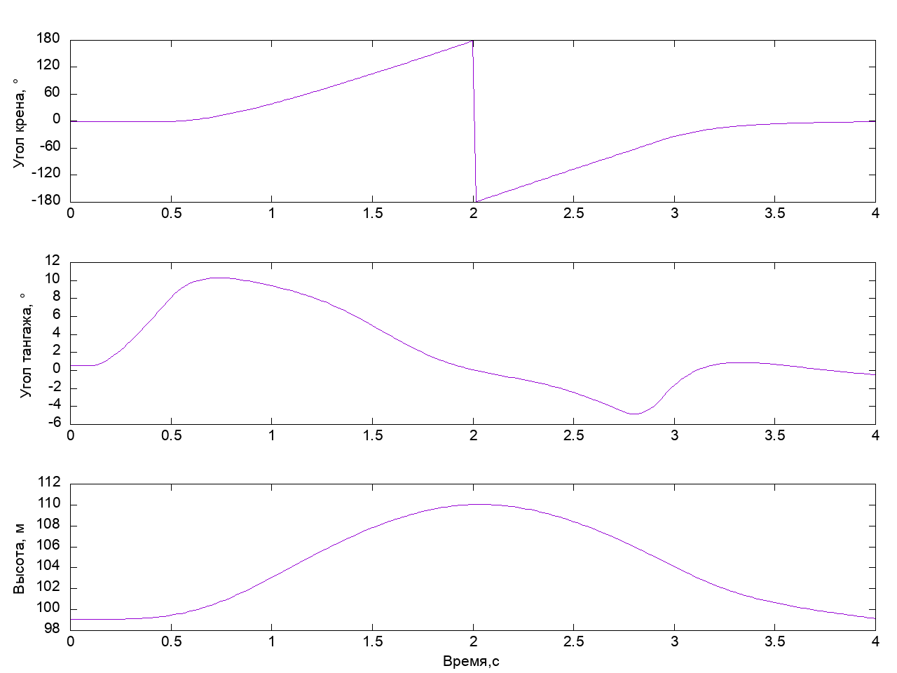
And really, if you remember that an airplane from a distance is a material point, then when rotating, the projection of the lifting force on the direction of gravity decreases and the plane starts to decline, but we don’t need it at all, because we want to perform a beautiful barrel without reduction. For this, before we began to reject the ailerons, you need to create a supply of vertical velocity. We take the wheel itself - the elevator is deflected - a moment of force arises about the z axis. The nose of the plane rises, and we begin to gain height - at this moment it is time to start the rotation. Add the elevator deflection to the script by 40 percent for 0.4 seconds before the beginning of the deflection of the ailerons and return it to the neutral position. 0.2 seconds before the end of the rotation, we take the helm completely by ourselves to eliminate the lowering of the nose of the aircraft:
The contents of the script.
<?xml version="1.0" encoding="utf-8"?> <runscript> <use aircraft="p51d" initialize="scripts/airborne"/> <run start="0" end="5" dt="0.0166666"> <!-- --> <event name="Trims"> <condition> sim-time-sec ge 0.0 </condition> <set name="simulation/do_simple_trim" value="1"/> </event> <!-- " " --> <event> <condition> sim-time-sec ge 0.1 </condition> <set name="fcs/elevator-cmd-norm" value="-0.4"/> </event> <!-- --> <event> <condition> sim-time-sec ge 0.5 </condition> <set name="fcs/aileron-cmd-norm" value="1"/> <set name="fcs/elevator-cmd-norm" value="0"/> </event> <!-- " " --> <event> <condition> sim-time-sec ge 2.75 </condition> <set name="fcs/elevator-cmd-norm" value="-1"/> </event> <!-- --> <event> <condition> sim-time-sec ge 2.95 </condition> <set name="fcs/aileron-cmd-norm" value="0"/> <set name="fcs/elevator-cmd-norm" value="0"/> </event> </run> </runscript>
Look what happened:
Here it is - quite decent, fast barrel. If we returned the elevator to a neutral position a little later, the device would gain a small height and, after deflecting the ailerons, would turn into a U-turn. The combination of the “steering wheel to itself” and “deviation of the ailerons” leads to the fact that the lifting force of the wing when tilting the vehicle starts to act along the normal to the current trajectory of the vehicle and distorts it the more, the more the elevator is tilted. You can try it yourself and make sure of it.
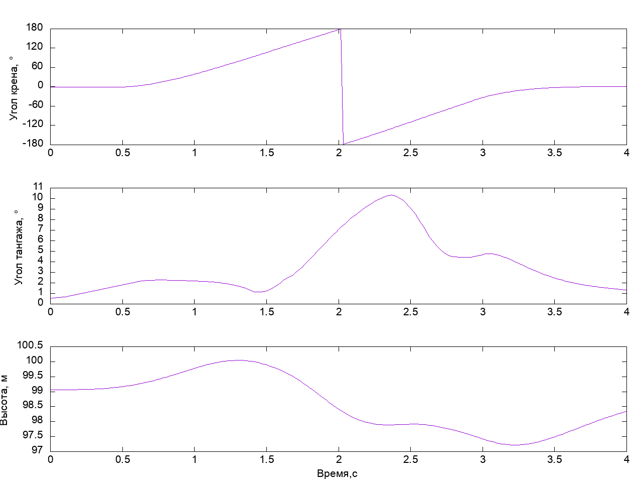
The previous barrel was made without reduction, the pitch angle at the exit of the barrel was not much different from the original. However, the height in the process of execution was changed to 12 meters. Let's try to more actively apply controls to minimize casting in height during the execution of the figure. In order not to turn the controls of the aircraft anyhow, let's take a look at Wikipedia and see how we are recommended to make a barrel. The main idea of the perfect barrel is to keep the longitudinal axis of the aircraft in a horizontal plane. For this, the elevator and the rudder are alternately used. At the beginning of the barrel, as usual, we use the elevator to gain vertical speed. We reject the ailerons - we start the rotation. When the plane turns around the longitudinal axis, the elevator and the rudder change places. Upon reaching a roll angle of about 90 degrees, the rudder deviation will raise or lower the nose of the aircraft in a vertical plane. In this regard, we reject the rudder in order to prevent the nose from lowering. Further, when the roll angle reaches 180 degrees, it is necessary to deflect the rudder from itself in order to keep the nose of the aircraft in the horizontal plane in an inverted flight. With a further turn, we repeat the deflections of the rudder with the opposite sign at a roll angle near - 90 degrees and finish the barrel with a slight deflection of the elevator “towards ourselves”. All these steps are expressed in the script below:
The contents of the script.
<?xml version="1.0" encoding="utf-8"?> <runscript> <use aircraft="p51d" initialize="scripts/airborne"/> <run start="0" end="10" dt="0.0166666"> <!-- --> <event name="Trims"> <condition> sim-time-sec ge 0.0 </condition> <set name="simulation/do_simple_trim" value="1"/> </event> <!-- " " --> <event> <condition> sim-time-sec ge 0.0 </condition> <set name="fcs/elevator-cmd-norm" value="-0.05"/> </event> <!-- --> <event> <condition> sim-time-sec ge 0.5 </condition> <set name="fcs/aileron-cmd-norm" value="1"/> </event> <!-- --> <event> <condition> sim-time-sec ge 0.6 </condition> <set name="fcs/elevator-cmd-norm" value="0"/> </event> <!-- --> <event> <condition> sim-time-sec ge 1.4 </condition> <set name="fcs/rudder-cmd-norm" value="0.7"/> </event> <!-- --> <event> <condition> sim-time-sec ge 1.6 </condition> <set name="fcs/rudder-cmd-norm" value="0"/> </event> <!-- " " --> <event> <condition> sim-time-sec ge 1.65 </condition> <set name="fcs/elevator-cmd-norm" value="0.5"/> </event> <!-- --> <event> <condition> sim-time-sec ge 2.35 </condition> <set name="fcs/elevator-cmd-norm" value="0"/> </event> <!-- --> <event> <condition> sim-time-sec ge 2.6 </condition> <set name="fcs/rudder-cmd-norm" value="-1.0"/> </event> <!-- --> <event> <condition> sim-time-sec ge 2.8 </condition> <set name="fcs/rudder-cmd-norm" value="0"/> </event> <!-- " " --> <event> <condition> sim-time-sec ge 2.75 </condition> <set name="fcs/elevator-cmd-norm" value="-0.4"/> </event> <!-- --> <event> <condition> sim-time-sec ge 2.95 </condition> <set name="fcs/aileron-cmd-norm" value="0"/> </event> <!-- --> <event> <condition> sim-time-sec ge 3.0 </condition> <set name="fcs/elevator-cmd-norm" value="0"/> </event> </run> </runscript>
Run and see what happened:
On roll, the device turned 180 degrees, while the total swing of the height change was about 2.5 m, which is five times less than in the previous case. We can say, we have got an almost perfect barrel.
Instead of conclusion
So, we looked at some of the principles for performing a barrel aerobatics and made sure that, acting reasonably, we can perform a barrel of good quality on the simulator. It would be nice to move on to practice, and with the help of what we propose to do it - model aircraft + stm32f103 + mpu9250. All these elements are easily accessible and cheap, so anyone can try it themselves. The results of trial, error and instruction for repetition are the subject of the following publications.
All Articles