Starting to learn STM32: What are registers? How to work with them?
We continue to consider basic issues.
In the previous lesson, we looked at working with bit operations and binary numbers, thereby laying the groundwork for a new topic. In this lesson we will consider another question: what are registers and how to work with them ?
List of articles:
- We start to learn STM32 or control the light rationally
- We start to study STM32: bit operations
- Starting to learn STM32: What are registers? How to work with them?
Memory and registers
One of the most important skills required when working with microcontrollers is the ability to interact with registers. Let's see for yourself what is it ?
In general, a register is a special kind of memory inside a microcontroller that is used to control the processor and peripheral devices. Each register in the ARM architecture is a memory cell and has a length of 32 bits, where each bit can be represented as a tiny switch with the help of which one or another microcontroller parameter is controlled.
Each of the registers has its own serial number - address. Register address is indicated by a 32-bit number represented in hexadecimal number system. By writing to the register address of a certain combination of ones and zeros, which are usually represented in hexadecimal, the control and management of this or that node in the MC is performed. Recall that in the program for working with bit operations, we could represent, in the form of a hexadecimal number, an arbitrary set of ones and zeros. In general, it is worth noting that there are two types of registers: general registers and special registers. The first are located inside the MK core, and the second are part of the RAM memory.
It is also worth noting that the Reference Manual , which we downloaded in the first lesson , is one large reference book on the registers contained in the target microcontroller, and the CMSIS library allows us to operate with the symbolic names of registers instead of numeric addresses. For example, we can access the register 0x40011018 simply using the symbolic name GPIOC_BSSR . We will consider specific configuration examples during the analysis of our program from the first lesson .
So, usually the structure of the register is described in the form of a small table with the indication:
- Register names and descriptions of its purpose
- Register addresses or offset from base address
- Default values after reset
- Type of access to the register cells (read, write, read / write)
- Values and descriptions of the parameters of the recorded bits
Let's look at an example of working with registers in a specific situation in order to get a general idea of how to configure a microcontroller.
Parsing code from the first lesson
So, let's remember the task that we solved in the first lesson using the ready-made example code: we needed to write a program that would ensure the alternate activation of two LEDs on the Discovery board (maybe not two, if you have another version of the Discovery board) with a time interval .
Let's take another look at the program code that we used to make our MK jerk with two legs on which our LEDs are located:
Main.c code
/* */ #include "stm32f0xx.h" /* */ int main(void) { /* GPIO */ RCC->AHBENR |= RCC_AHBENR_GPIOCEN; /* PC8 PC9 Output*/ GPIOC ->MODER = 0x50000; /* Output type Push-Pull */ GPIOC->OTYPER = 0; /* Low */ GPIOC->OSPEEDR = 0; while(1) { /* PC8, PC9 */ GPIOC->ODR = 0x100; for (int i=0; i<500000; i++){} // /* PC9, PC8 */ GPIOC->ODR = 0x200; for (int i=0; i<500000; i++){} // } }
First of all, when working with STM32, even for such a simple task as turning on and off the LED, we need to first answer a number of questions:
- Where are our LEDs connected? What is the conclusion of the microcontroller?
- How to enable clocking on the desired GPIO port?
- How to configure the pins of the GPIO port we need in order to enable the LED to turn on?
- How to turn on and off the LED?
Answer them in order.
Where are our LEDs connected? What is the conclusion of the microcontroller?
In order to see where what is on the Discovery board, and in particular, the LEDs we need, you need to open the Schematic file, either the one we downloaded from the ST site , or directly from Keil:
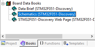
Having opened Schematic we will see the scheme of all that is on the board - the ST-Link scheme, the binding of all peripherals and much more. At the moment we are interested in two LEDs, we are looking for their designation:
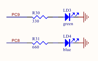
As we see, our LEDs are connected to the GPIOC port for 8 and 9 pin.
How to enable clocking on the desired GPIO port?
In general, any work with peripherals in STM32 microcontrollers is reduced to the standard sequence of actions:
- Enable clocking of the corresponding peripheral module. This is done through the RCC register by submitting a clock signal directly from the bus on which this module is located. By default, all peripheral clocking is disabled to minimize power consumption.
- Configuration via control registers by changing parameters specific to a specific peripheral device
- Direct launch and use of the results of the module
That is, to get started, we need to run clocking on the GPIOC port. This is done directly through the access to the RCC register responsible for clocking everything and switching on the clock signal from the bus to which our GPIO port is connected.
Attention! The question regarding the clocking system, its settings and usage will be discussed in detail in a separate article.
Find which bus our GPIOC port is connected to can be found in the Datasheet on our MC in the Memory Mapping section in Table 16. STM32F051xx peripheral register boundary addresses.
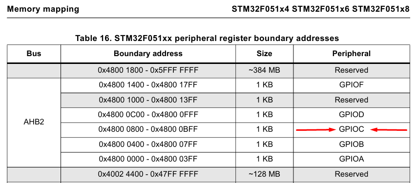
As you have already noticed, the bus we need is referred to as AHB2. In order to learn more about the register in which clocking is enabled on the GPIO port on the AHB bus we need, go to the appropriate section in the Reference Manual. By the name of the registers, we can determine the one we need:
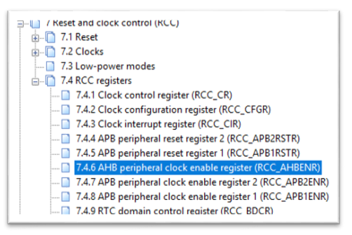
Go to this item, and we see our 32-bit register, its offset address, the default value, the way to access the register, and the enumeration of what each bit in the register is responsible for.

We look at the table and see something resembling the option to enable clocking on GPIO ports. Go to the description and find the option we need:
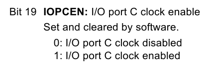
Accordingly, if we set 19 bits to “1”, then this will enable clocking on the I / OC port — that is, on our GPIOC. Besides, we need to separately enable one bit from the group, without affecting the others. we should not interfere and change other settings unnecessarily.
Based on the materials of the last lesson, we know that in order to set a certain bit, you need to use the logical operation "OR" to add the current register value with a mask that contains those bits that need to be included. For example, add the value of the register RCC-> AHBENR by default, i.e. 0x14 and the number 0x80000 thus enable GPIOC clocking by setting 19 bits:

How can we do this from the program? Everything is quite simple. In this case, we have two options:
- Record in the register directly the numerical value of the register directly through its address.
- Setup using the CMSIS library
There are no special problems in writing the value to the register directly, but there are a couple of significant drawbacks. Firstly, such code becomes unreadable and secondly we cannot immediately determine which register refers to one or another address in memory.
That is, we could contact the addresses of the registers directly at the address and write like this:
__IO uint32_t * register_address = (uint32_t *) 0x40021014U; // *(__IO uint32_t *)register_address |= 0x80000; // 19
The second option seems to me the most attractive, because The CMSIS library is organized in such a way that the register can be accessed using only its name. During compilation of the text of the program, the preprocessor will substitute all numerical values of the register address automatically. Let's analyze this question in more detail.
I propose to open our project, which we did in the first lesson, or download previously prepared from here and delete the entire contents of the program, leaving only the connected header file, the main () function and instructions to enable clocking (we will need it for detailed code parsing).
Our code will look like this:
/* */ #include "stm32f0xx.h" /* */ int main(void) { /* GPIO */ RCC->AHBENR|=RCC_AHBENR_GPIOCEN; }
Let's dig into the CMSIS library for review.
In order to quickly go to the place where one or another constant or variable is declared, Keil implements a convenient function. Right-click on the constant we need, for example, on the RCC:

And we are transferred to the depths of the CMSIS library, in which we will see that all the registers available for programmatic control have the form of TypeDef structures, including our RCC:

Having failed in a similar way in RCC_TypeDef we will see a structure in which all fields of our register are described:

Accordingly, we can safely refer to the register we need by writing the type PERIPH_MODULE-> REGISTER and assign it a specific value.
In addition to the mnemonic notation of registers, there are also notation for specific bits. If we fail to declare the parameter RCC_AHBENR_GPIOCEN from our program, we will also see the declaration of all parameters:
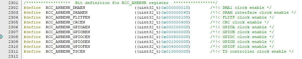
Thus, using the CMSIS library, we get a concise readable record of the parameter we need in the register, through the installation of which we start clocking on the port we need:
/* GPIO */ RCC->AHBENR|=RCC_AHBENR_GPIOCEN;
As an assignment: using Keil's capabilities, determine how the address of the RCC-> AHBENR register is 0x40021014.
How to configure the GPIO pins we need in order to enable the LED?
So, we know that the LEDs we need are connected to the GPIOC port to the PC8 and PC9 pins. We need to set them up so that the LED lights up. I would like to immediately make a reservation that we will look at the GPIO ports in more detail in another article, and here we will concentrate on working with registers.
First of all, we need to switch the operation mode of the PC8 and PC9 pins to the Output mode. The remaining port settings can be left as default. Go to the Reference Manual in section 9. General-purpose I / Os (GPIO) and open the item responsible for the operation mode of the pin ports of the GPIO port and see that the MODER register is responsible for this parameter:
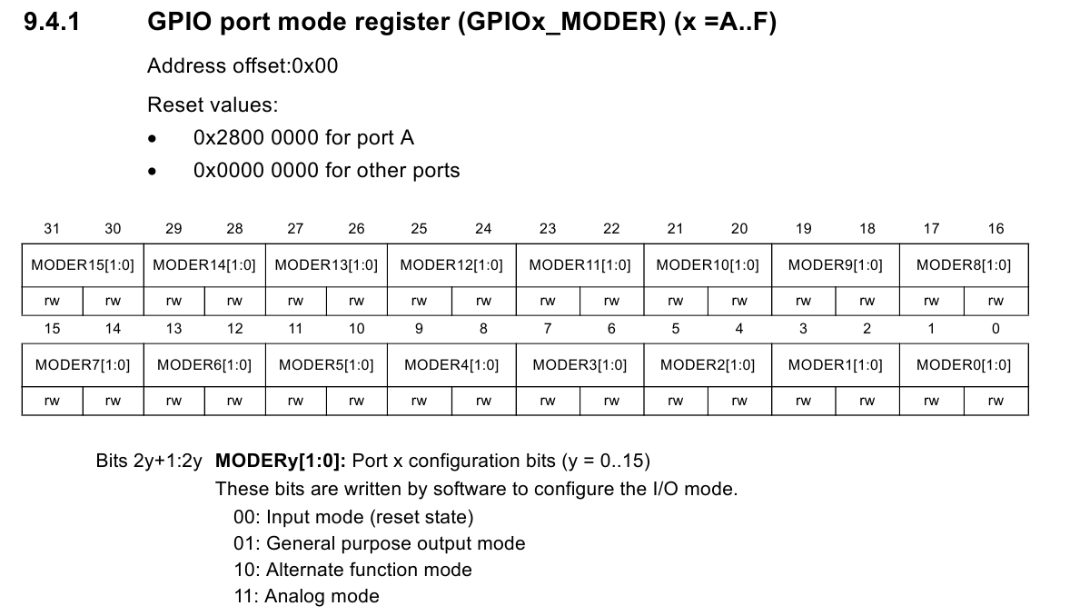
Judging by the description, to install the PC8 and PC9 pins in Output mode, we must write 01 to the corresponding fields of the GPIOC register.
This can be done through direct installation using numeric values:
- We form number for record:
- Assign this value to our register:
/* PC8 PC9 Output*/ GPIOC->MODER |= 0x50000;
Or through the use of definitions from the library:
/* GPIO */ GPIOC->MODER |= GPIO_MODER_MODER8_0 | GPIO_MODER_MODER9_0;
After this instruction, our pins PC8 and PC9 will go into Output mode.
How to turn on the LED?
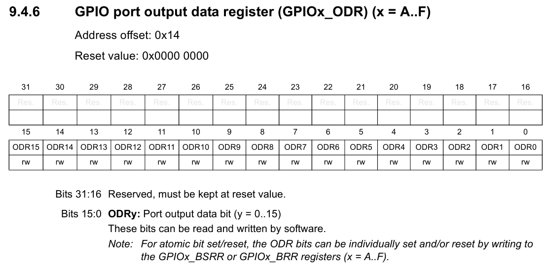
If we pay attention to the list of available registers for managing the GPIO port, we can see the ODR register:
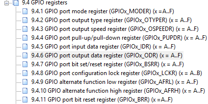
Each of the corresponding bits is responsible for one of the port pins. You can see its structure below:
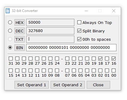
In order to provide alternating changes in the states of the LEDs, it is necessary to turn on / off 8 and 9 bits with a certain time interval. That is, alternately assign a register value of 0x100 and 0x200.
We can do this by directly assigning values to a register:
GPIOC->ODR = 0x100; // PC8, PC9 GPIOC->ODR = 0x200; // PC9, PC8
We can through the use of definitions from the library:
GPIOC->ODR = GPIO_ODR_8; // PC8, PC9 GPIOC->ODR = GPIO_ODR_9; // PC9, PC8
But since the microcontroller is working very quickly - we will not notice the change of the states of the LEDs and it will visually seem that they both are lit constantly. In order for them to really blink alternately, we will introduce an artificial delay in the form of a cycle which will take the MC to useless calculations for a while. The result is the following code:
/* PC8, PC9 */ GPIOC->ODR = GPIO_ODR_8; for (int i=0; i<500000; i++){} // /* PC9, PC8 */ GPIOC->ODR = GPIO_ODR_9; for (int i=0; i<500000; i++){} //
On this initial acquaintance with the registers and methods of working with them, we can finish.
Checking the results of our code
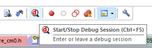
A small nice addition at the end of the article: Keil has a great Debug tool with which we can step by step execute our program and view the current status of any peripheral block. To do this, after downloading the firmware after compiling, we can click the Start Debug Session button:
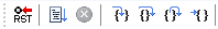
The Keil runtime will switch to debug mode. We can control the program flow using these buttons:
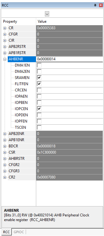
And there is one more convenient function of working with peripherals in debug mode, it allows you to view the current status of registers and change their state with a simple mouse click.
In order to use it - you need to go to the appropriate peripheral unit and a window opens on the right with the indication of registers and their value.

If you click on one of the items in this menu, you will see the address of the register and its brief description. You can also view a description of each individual register parameter:
Try yourself to step through the program, turn on / off the LEDs without using the program, but using this mode of operation with a microcontroller. The scope for fantasy here is vast. Also try to play with the delay times, make simultaneous blinking with both LEDs. In general, experiment! )
See you in the next articles!
List of articles:
All Articles