Teach Arduino to print telegrams
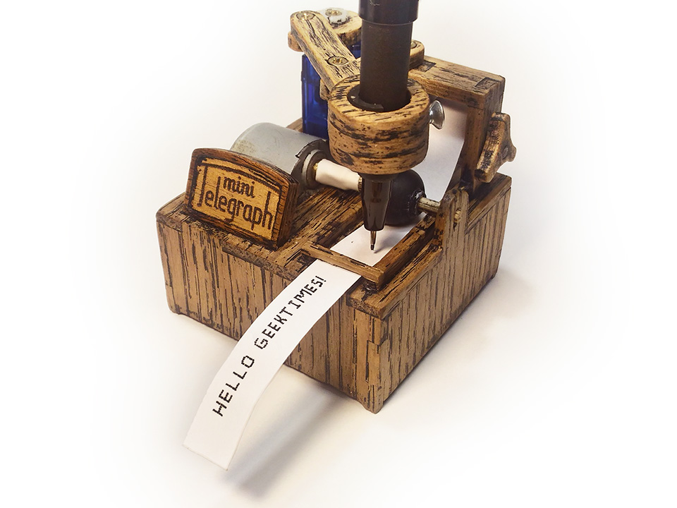
A small project on Arduino that prints notifications to your phone: messages from various instant messengers, news from Twitter and everything else. This “telegraph device” was conceived as an interesting toy without serious use, but as it turned out, it was extremely pleasant to receive messages in the form of paper telegrams. Under the cut - a description of the apparatus and a detailed tutorial.
Briefly about how this all works.
As a matter of fact, the whole printing process is reduced to three simple operations: Movement along the X axis (pulling the ribbon), movement along the Y axis (movement of the handle), and the process of leaving a mark on the paper.
Watch the video
Movement along the Y axis is carried out using the P. L. Chebyshev's lambda mechanism , which transforms the rotational motion into a nearly straight line.
Stretching the tape is carried out using a silicone liner from the headphones, rotated by a stepper motor. Ideally, the tape should be pulled through two rollers pressed against each other, but such a solution would significantly complicate the design, so the choice fell on the simplest of working options.
In similar projects (homemade plotters, printers, etc. ...), the drawing process is carried out by means of a translational (or close to translational) movement of the handle up and down. Such a system is too cumbersome to be placed on the lambda mechanism, so I went a little different way. In the case there is a solenoid, to which a small platform is attached, which lifts the paper tape. Such a decision is hardly applicable in other projects, but it fits here as well as possible. All elements are located in a 64 × 64 mm plywood case.
The device itself prints literally everything that it comes to the serial port. A 128 character font is sewn into the sketch:

For this program was written in Java, which converts the image into a description of the byte array in C, if desired, the font can be remade for themselves.
I also developed a small android application whose task is to catch all the push notifications displayed on the phone, and then send them in the background to arduino via bluetooth.
Screen application 
What we need
- Arduino Mini. This is a miniature version of the Arduino Uno with very compact dimensions. It is not necessary to use it. If you do not want to push all the control electronics into the device case, then any other board, for example, Arduino Uno or Leonardo, will do. You can also look towards the Iskra Mini - a complete analogue of the Arduino Mini.
- Servo SG-90. The smallest and cheapest servos from the existing ones.
- Stepper motor 28BYJ-48. Very cheap stepping motor with high positioning accuracy - 4096 steps per revolution. Usually, it is already sold with the ULN2003 driver.
- Solenoid 5B. These devices are not so often used in homemade products, such as servos. Their essence is as follows: these are small electromagnets that, when a current is applied to them, push the stem in them. They can perform very fast forward movements that can be controlled.
- Bluetooth module HC-06. Needed to communicate with the outside world. You can also think about connecting to wifi via esp8266 instead of using a bluetooth module
- Rubber ear cushions (inserts) for headphones. It is necessary for the manufacture of the mechanism, pulling the paper. The larger the size of the ear cushion, the better.
- Axis 3mm. The choice of material is wide: you can use wooden skewers with a diameter of 3mm or screws with sawed off caps.
- Glue. For greater accuracy, it is better to use 3 types of glue: PVA for gluing wooden parts, thermal glue and super glue for fixing the rest of the elements.
- Sandpaper. Even with very accurate parts manufacturing, they will need to be adjusted, so without polishing - nowhere.
- Plywood 4 mm. Can be found in the building or hobby store. Perhaps other options are suitable, for example, plexiglass.
- Blueprints. They can be taken here .
And in DXF format - here. - A lot of little things ...
- Capillary pen or marker. Ballpoint pens and gel pens, as well as pencils, are much worse, since the mark left by them on paper is much less distinct.
- Small screws. Diameter not exceeding 2 mm. Often these are used in all sorts of Chinese toys.
- Heat-shrink tubing. Need to lengthen the shaft of the stepper motor. The internal diameter before heating is around 6 mm.
- Switch. Any that you enjoy. You can look towards the small buttons with fixation.
- Power connector. 2.1 mm Barrel Jack.
- Diode. Nominal and characteristics of a large role will not play, you can vypayat from some old radio.
- Transistor switch or relay . More about them will be written below.
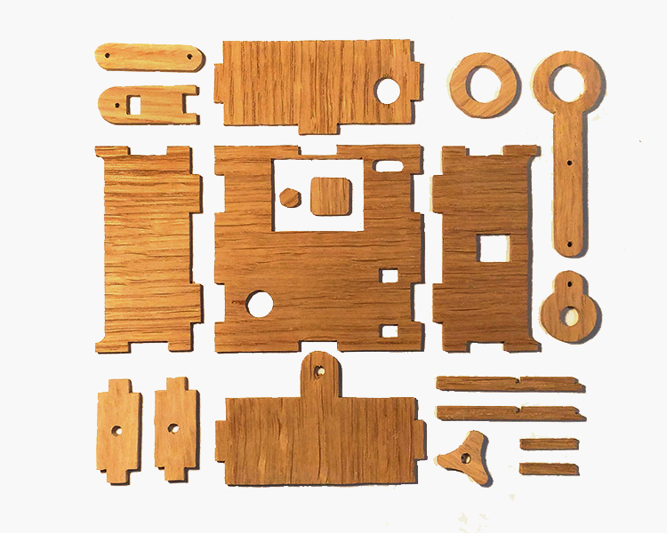
Parts manufacturing
This stage depends on your desire and on your capabilities. You can cut on the machine or cut out all the details manually. By the way, it is not at all necessary to repeat the project to a tee. For example, you can not try to shove all the control electronics in the case of the device. Or, having understood the principle of work, to do something similar literally “on the knee”, and still everything will work.
For those who plan to do everything manually
In order to make all the parts, you will need: jigsaw (jigsaw), drill (drilling machine), printer, sandpaper and, if necessary, needle files.
The algorithm is as follows. Print the drawings, stick them on the plywood. Then drill all the necessary holes in the places of the internal contours. The contours of the grooves should be cut out, retreating a little space (~ 0.2-0.5 mm) inward, so that the spikes (after a small processing with a file) then fit them. After that, we cut out the inner contours, tear off / sow the paper, which we have pasted, and grind. There is nothing difficult in this, the main thing is to work carefully and not rush.
The algorithm is as follows. Print the drawings, stick them on the plywood. Then drill all the necessary holes in the places of the internal contours. The contours of the grooves should be cut out, retreating a little space (~ 0.2-0.5 mm) inward, so that the spikes (after a small processing with a file) then fit them. After that, we cut out the inner contours, tear off / sow the paper, which we have pasted, and grind. There is nothing difficult in this, the main thing is to work carefully and not rush.
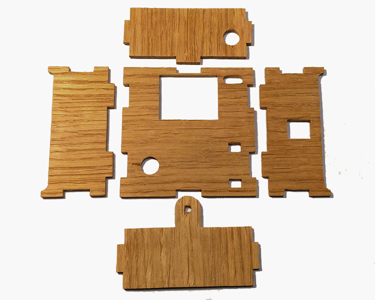
We collect the body
So far there is nothing difficult: just take the parts and glue them together. Ensure that there is no excess glue on the parts.

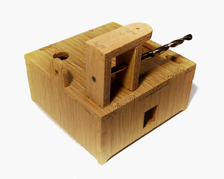
Install the coil holder
When gluing this element, I recommend using a drill to keep the coaxiality. First, the side walls are glued to the body, and then the cover is installed on them. Watch for perpendicularity - the lambda mechanism depends on the position of the hole on the lid of this holder.

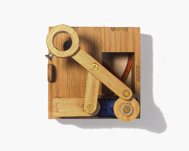
Putting lambda mechanism

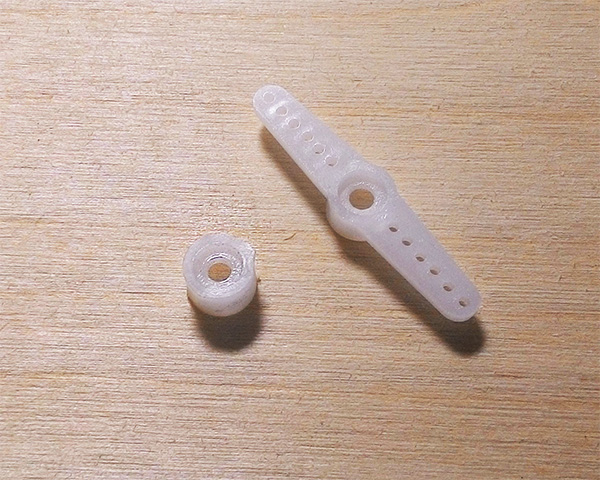
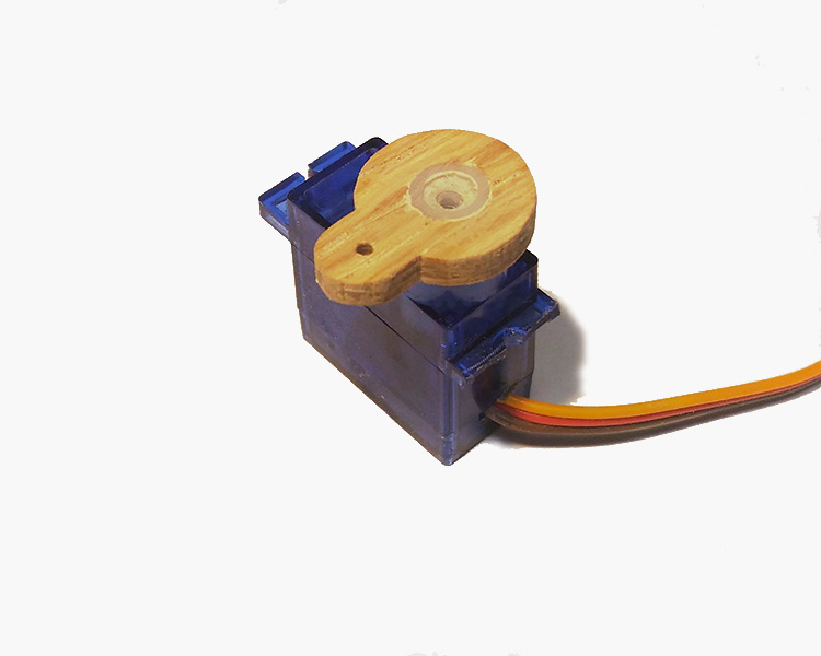
So we got to the first crucial stage - the assembly of the lambda mechanism. First you need to make a shoulder for the servo. Included with each servo is a few plastic rockers. It is necessary to take one of them and trim-grind as shown in the figure below. And then paste it into the blank for the shoulder.
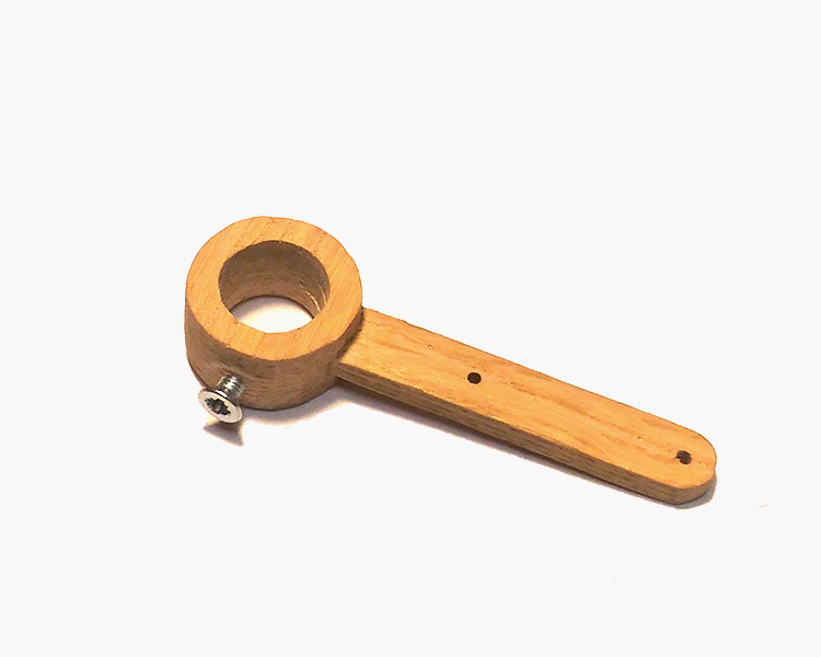
Next, we make a shoulder with a “pen holder”. Hole for writing instrument is better to verify in advance. Most likely, it will be around 8-9 mm. Glue the two rings on top and bottom. So that they do not move out, you can insert a handle or a drill of a suitable diameter into the hole. After the glue dries, we grind the inner and outer surfaces of the ring until its surface becomes sufficiently smooth. From the side we drill a hole under the gland screw.
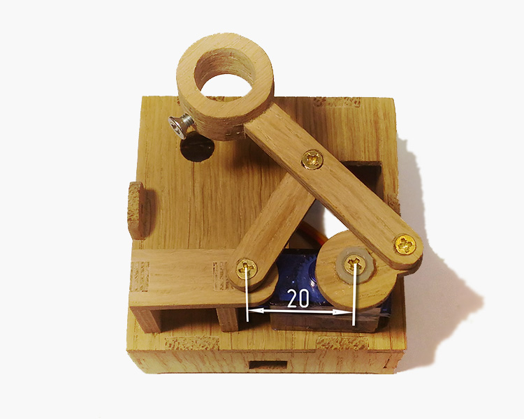
Now you can proceed to the assembly of the lambda mechanism. First you need to glue the servo to the glue so that the distance from its axis to the hole on the coil holder is exactly 20 mm. Next, turn the servo counterclockwise until it stops, and then assemble the entire structure according to the photo:
You can check the functionality of this mechanism if you connect a servo drive to the Arduino and load a sketch from the samples: Servo → Sweep (By default, the servo connects to pin 9). I give the code for the sketch below, just in case.
Servo sweep
#include <Servo.h> #define MIN_ANGLE 150 #define MAX_ANGLE 180 Servo servo; void setup() { servo.attach(9); } void loop() { for(int i=MIN_ANGLE; i<=MAX_ANGLE; ++i) { servo.write(i); delay(15); } for(int i=MAX_ANGLE; i>=MIN_ANGLE; --i) { servo.write(i); delay(15); } }
At this stage, you can choose the working angle range for the servo, setting the values MIN_ANGLE and MAX_ANGLE (this range is approximately 150 ° ... 180 °), this will be needed later. If the mechanism does not work smoothly, try to loosen the screws or lay the washers.
Set the paper slide
Now we have to have almost a jewelry job: to make a sled along which the paper tape will move, as well as a platform that will be attached to the solenoid. Long slats need to be glued to the base so that their ends rest against the rack for the coil, and the distance between them should be 13 mm.
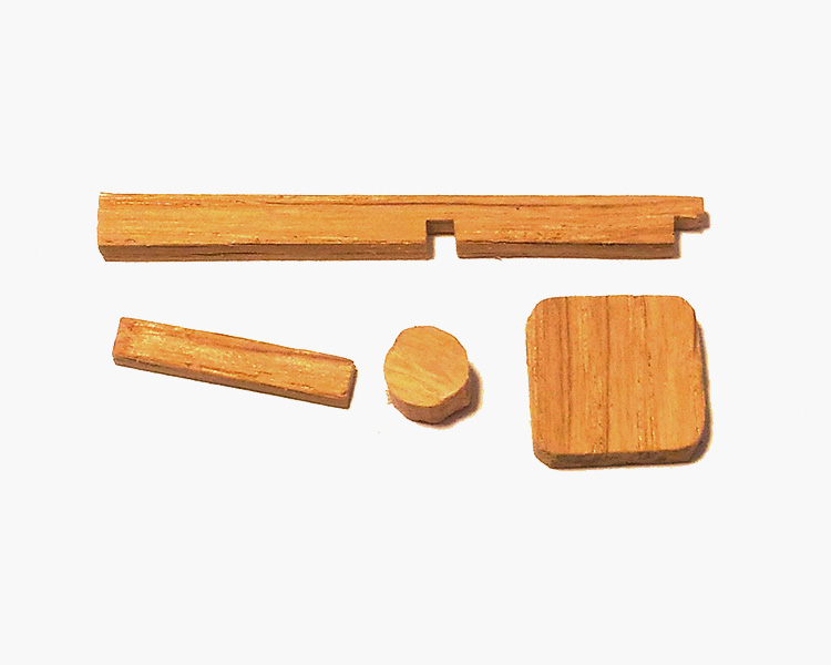
Further on these small rivers the top short stick is pasted. The assembly of this site is easier to produce on super glue. Try not to leave excess glue, it can greatly interfere with pulling the paper.
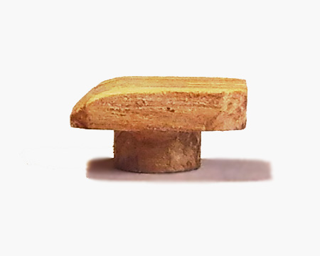
The area must be trimmed to the minimum possible thickness (≤ 1.5mm), and one edge should be wedge-shaped so that paper can be pushed over it more easily. You can immediately take and make this platform from a relatively thin wooden ruler or an unnecessary plastic card. Next to it in the center is glued round stand. Next, a solenoid is glued inside the case so that its core is located in the center of the hole. After that, on the super-glue gently glue the pad to the solenoid rod. It should look like this:


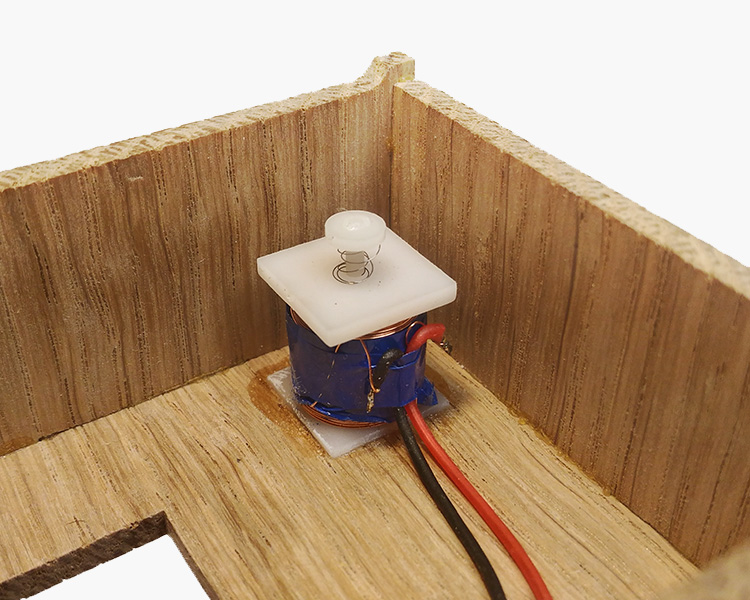
At the beginning of the test, just try to apply a voltage of 5V to the solenoid. If the area has risen, then everything is fine. If this does not happen, then try changing the polarity. If this does not help, then try to poke the solenoid rod yourself. In case he moves or moves with great effort, it means that extra glue got there.
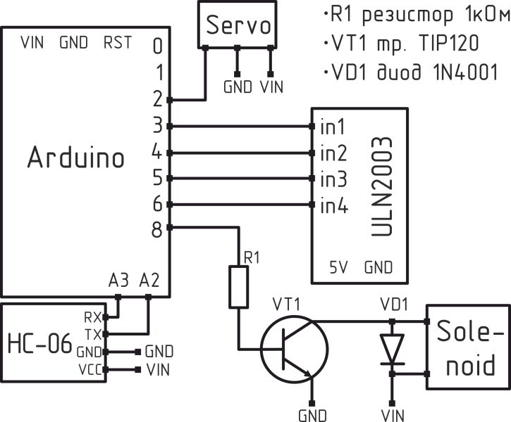
The connection of the solenoid to the control board is not carried out directly : for this you need to use an electromagnetic relay or a transistor switch. You can look in the direction of ready-made solutions, for example, here . It will also be useful to read this article . I used the Soviet relay RES49. Below is a diagram of the connection of a solenoid through the transistor TIP120.

The use of a diode in the circuit is required. It performs a locking function here, without it the Arduino board will constantly reboot. The characteristics of the diode do not play a big role, it can be found and dropped from any old board.
Pulling mechanism
In order for the lingering mechanism to work, it is necessary to ensure minimal friction of the paper tape on the surface of the body. It is possible to reduce friction by rubbing a paraffin abundantly on the track or, at worst, sticking a strip of transparent tape on it.

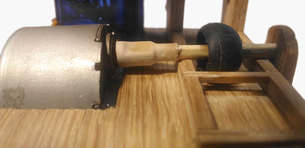
We proceed to the manufacturing procedure. We cut off the shaft of the required length (28 mm), after which we outline the place where the ear cushions will be located from the headphones, we wind several turns of electrical tape on the shaft so that our “roller” fits tightly onto it.
Next, pre-biting off the stepper motor "ears" for attachment to the thread, push it into a niche. Then, using a heat shrink tube, fasten the axis to the motor shaft. If everything worked out, fix the motor with hot melt glue. Try to make the shaft perpendicular to the track and parallel to the horizontal plane. The embouchure and the motor shaft should be immediately gently glued to the axis with superglue.
To check, we connect the stepper motor through the driver to the control board and load into it a sketch from the samples: Stepper → stepper_oneStepAtATime. You only need to change the value of the stepsPerRevolution variable from 200 to 4096 and remove the delay (500).
I corrected the code with corrections, just in case, below.
stepper_oneStepAtATime
#include <Stepper.h> const int stepsPerRevolution = 4096; Stepper myStepper(stepsPerRevolution, 8, 9, 10, 11); void setup() { } void loop() { myStepper.step(1); delay(5); }
After loading the sketch, the stepping motor should start a smooth and slow rotation. You can try to slip a piece of paper tape under the roller. It should also begin a smooth and slow motion. If this does not happen, then it is probably a matter of high surface roughness, which is corrected by fine-grain sandpaper.
Coil Axis
This is perhaps the easiest stage among others. We take an axis ~ 25 mm long, one remaining unused part and glue them together. You may have to lay the shaybochka between the stand for the coil and the part for which I did not come up with a name.


Now a few words about the paper tape. Its optimum width is 11mm. You can come up with several technologies for its manufacture. For example, take a roll of check tape (roll of tracing paper, graph paper, etc ...) and just cut it. I liked the option of cutting A4 sheet into strips, which are then carefully glued into a tape of the desired length.
Putting it all together
If all the mechanisms are already working, now it’s time to start the most difficult stage - to make them work together. First you need to collect / solder the scheme below.
I placed all the electronics in the device case as follows (someday I will learn how to solder properly, but not this time):

Also install the switch and power connector. As a switch, I used the Soviet MT-1. I recommend taking something smaller, because to use such a large toggle switch in such a small case is an unaffordable luxury, this place is better to take something more useful.
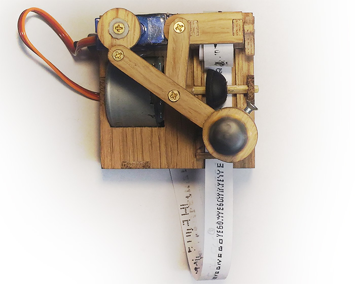
Several photos of the finished device 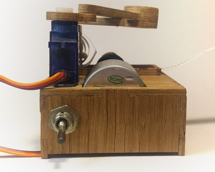

We proceed to debug the program. To do this, take the sketch HERE and load it into the board.
I tried to comment it out in as much detail as possible, so I hope it will be as clear as possible. When you start the program, the device prints the word "HELLO", and then it prints literally everything that comes to the Bluetooth module. Your task at the debugging stage is to select the values DOT_UP_DELAY, DOT_DOWN_DELAY, SERVO_MAX, SERVO_STEPS, SERVO_DELAY and LINE_TAB in the sketch so that the inscription “HELLO” at the start of the program goes out as beautiful as possible.
Once the desired print quality is achieved, you can try to send some message via bluetooth. To do this, you can download any application to your phone, the title of which contains the phrase “Bluetooth terminal”, connect to the device (most likely, it will be displayed as hc-06) and start sending messages to it. Note that the buffer size of the serial port on the Arduino is 64 bytes. This means that if you send a message that is too long, not exactly what you want will be printed.
I also wrote a small android application that catches push notifications displayed on your phone and sends them to print. It can also be used as a simple bluetooth terminal. Versions of android from 4.3.0 are supported. You need to remember to allow the application access to system notifications, otherwise nothing will work.
How to allow an application to access notifications 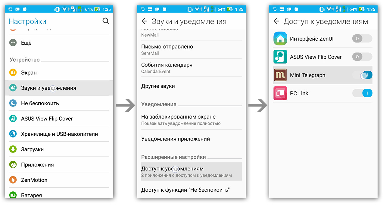
This is a beta version of the application, if necessary I will modify it and expand the functionality.
Decorative part
This stage is not at all mandatory, and in some cases it is more likely to harm. Here everything is to your taste. In my case, for example, I aged all the wooden parts with a patina and covered with a thin layer of varnish, and also made small signs “Mini Telegraph”, “ON / OFF” and a sign with the signature.
Summing up
That's all. I hope you enjoyed this small project. Perhaps you found some interesting ideas or solutions. With a high degree of probability I will refine
this project. I will be glad to any questions, advice and suggestions in the comments. If you can do something similar, it will be very interesting for me to look at it, if you have any questions, you can write here .
List of articles that may be useful
List
A deep understanding of what you work with will help avoid many unpleasant mistakes.
(Some articles in English, but with beautiful color pictures)
(Some articles in English, but with beautiful color pictures)
- About servos
- Pro stepper motor 28BYJ-48
- About solenoids connection
- How to flash Arduino mini
- Pro Bluetooth Module
All Articles