We start to learn STM32 or control the light rationally
Small introduction
Once, having come to another rented apartment, I ran into a certain inconvenience, which was quite stressful: the light switch in the main room was behind the wall-cabinet, which was bolted to the wall, and its rearrangement was impossible because it took much time and effort. I wanted to solve this problem very much and one thought occurred to me: to make a remote control for lighting control!
It was with the idea of creating my own remote control for controlling the light in the room that my hobby for electronics, microcontrollers and various radio devices began.
List of articles:
- We start to learn STM32 or control the light rationally
- We start to study STM32: bit operations
- Starting to learn STM32: What are registers? How to work with them?
After that, I began to study this topic, to get acquainted with the basics of electronics, examples of devices, to learn how people implement this kind of device. After searching for information on the topic of how to start studying microcontrollers, I learned what an Arduino is, what they eat with, and how to work with them. The easy solution looked very attractive, because as far as I understood at that time, the code is going to be done once or twice. But concluding that I did not find out what was going on inside the microcontroller beyond the framework of the Arduino-sketches, I decided to look for a more interesting option, which implied in-depth study and immersion in the wilds of microcontroller technology.
In the company in which I work, there is a development department, and I decided to contact the engineers so that they would direct me on the right path and show where I could start solving my task. I was strongly discouraged from exploring the Arduino and in my hands there was an unknown and incomprehensible green scarf on which were visible inscriptions, small letters, various electronic components.
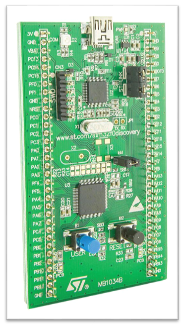
All of this for me at that time seemed inexplicably difficult, and I even came into some confusion, but I was not going to give up on the implementation of the task. So I got acquainted with the STM32 microcontroller family and the STM32F0-Discovery board, after studying which I would like to make my device for the purposes I need.
To my great surprise, such a large community, articles, examples, and various materials on STM were not as abundant as for Arduino. Of course, if you search there are many articles "for beginners" which describes how and where to start. But at that time it seemed to me that all this was very difficult, many details that were not interesting for the novice's inquiring mind, were not told. Although many articles were characterized as “learning for the smallest,” it was not always with their help that it was possible to achieve the desired result, even with ready-made code examples. That is why I decided to write a small cycle of articles on programming on the STM32 in the light of the implementation of a specific idea: a lighting control desk in the room.
Why not AVR / Arduino?
Anticipating statements that it would be early for an inexperienced newcomer to rush immediately to the study of such a complex MK as STM32 - I’ll tell you why I decided to go this way, without delving into and without familiarizing with the Atmel processor family .
First, the price-functional ratio played a decisive role, the difference can be seen even between one of the cheapest and simplest MKs from ST and the rather fatty ATMega:
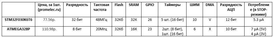
After what I saw significant differences between the price and the capabilities of the AVR and STM32 - I decided that I would not use AVR in my design =)
Secondly, I previously tried to determine for myself the set of skills that I would have received by the time I reach the desired result. If I decided to use Arduino, it would be enough for me to copy the finished libraries, to distribute the sketch and voila. But an understanding of how digital buses work, how a radio transmitter works, how everything is configured and used - in this situation I would never have come. For myself, I chose the most difficult and thorny path, so that on the way to achieving the result - I would get the maximum of experience and knowledge.
Third, any STM32 can be replaced with another STM32, but with better performance. And without changing the inclusion scheme.
Fourthly, people engaged in professional development are more likely to use 32-bit MK, and most often these are models from NXP, Texas Instruments and ST Microelectronics. Yes, and I could at any time approach my engineers from the development department and find out how to solve this or that problem and get advice on issues of interest to me.
Why it is worth starting studying STM32 microcontrollers using Discovery board?
As you have already understood, we will begin the acquaintance and study of the STM32 microcontroller with you, dear readers, with the use of the Discovery board. Why Discovery, and not its own fee?
- On any Discovery board, there is a built-in ST-LINK programmer / debugger that connects to the computer via USB and can be used both for programming the microcontroller on the board and external devices by removing / installing the appropriate jumpers. That is a plus to everything - we also save money by getting a two-in-one solution: a microcontroller and a programmer.
- Discovery cards have a full wiring of all pins directly from the microcontroller to the pins of the board. For ease of use, I stuck Discovery into two breadboard boards as well.

- 3. There is always a certain number of peripheral devices on the board, for example, accelerometers, microphones, displays, sensors, and many others. Different Discovery boards have various body kit options. If anyone is interested, you can find out more on the manufacturer's website.
What do we need to develop in addition to the Discovery board?
In our work with the Discovery card, we will need a number of irreplaceable things, without which we can not do:
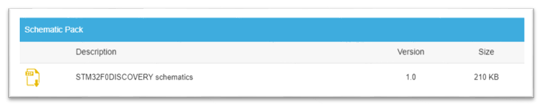
- Scheme of the board to see where, where and what is connected. You can get the scheme on the page of the manufacturer of your board in the Schematic Pack section. You can download the schemes by scrolling through the page a little lower in the block indicated in the picture:
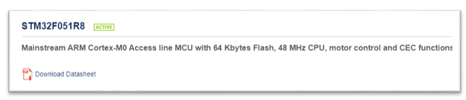
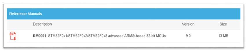
- Datasheet on our microcontroller, so that at any convenient time you can see the pinout, characteristics, parameters and other necessary information for work. In my case, this is STM32F051R8T6 . Link to datasheet is in the page header:
- We also need a reference manual for our microcontroller. This is a document in which the methods and approaches to working with the MK core, with its clock unit, with the periphery, etc., are described in detail. It also contains a description of all registers MK, all options and settings MK and peripherals. Probably, this is the most important file without which it would be very difficult to figure out how and what works inside the MC. You can download the file using the link on the microcontroller page:
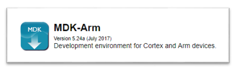
- And finally, we need to set up a development environment in which we could create programs for our MC and quietly compile and flash our programs. At one time, I tried almost all of the most popular IDEs and settled on Keil uVision 5. In my opinion, this development environment seemed to me the most convenient and easy to learn. A built-in debugger, ready-to-use and easy-to-connect low-level libraries, a huge number of examples, and a conveniently organized working interface and IDE space were decisive factors that influenced my choice. You can download this IDE from the official site , but simple registration is required :. There is, however, one small limit on the size of the downloadable firmware in 32kB. This IDE is paid. But for us this will be more than enough. We will need MDK-Arm:
Let's start the initial setup and preparation of the IDE to work!
After the installation file of our IDE is downloaded, you can proceed with the installation. Follow the installer instructions to complete the installation process. After all the files necessary for work are copied, the window of the installer of software packages for the development of the Pack Installer will appear. This installer contains low-level libraries, Middleware, examples of programs that are regularly updated and updated.
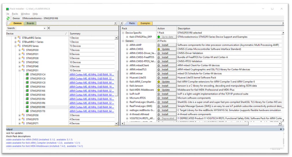
To start working with our board, we need to install a number of packages necessary for work and we need to find a microcontroller with which we will work. You can also use the search at the top of the window. After we have found our MC, we click on it in the second half of the window and we need to install the following list of libraries:
- Keil :: STM32F0xx_DFP is a complete software package for a specific family of microcontrollers, including manuals, datasheets, SVD files, libraries from the manufacturer.
- ARM :: CMSIS is the Cortex Microcontroller Software Interface Standard package, which includes a complete set of ARM libraries for supporting the Cortex core.
- Keil :: ARM_Compiler is the latest compiler version for ARM.
After installing the required packs, you can proceed to setting up the IDE and our debugger / programmer. To do this, we need to open the main window of Keil and create a new project.

To do this, go to the menu Project -> New uVision Project and select the folder in which we save our project.
After Keil will ask us which MK will be used in the project. Select the desired MK and click OK .

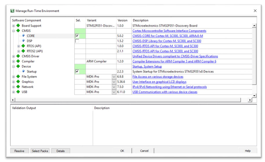
And a window will appear again, already familiar to us, in which we can connect the modules of interest to the project. For our project we need two modules:
- The core of the library CMSIS , which declared the settings, addresses of registers and much more from what is necessary for the operation of our MC.
- Startup-file , which is responsible for the initial initialization of MK at startup, the declaration of vectors and interrupt handlers and much more.
If all the dependencies of the plug-in are satisfied, the manager will signal us in green:
After we press the OK key, we can start creating our project.
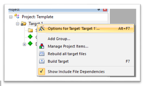
In order to configure the project parameters and configure our programmer, right-click on Target 1 to open the corresponding menu.
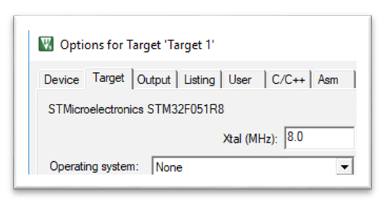
In the main menu of the project, set the Xtal parameter to 8.0 MHz . This parameter is responsible for the frequency of the quartz oscillator of our MC:
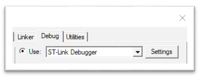
Next, go to the setting of our programmer / debager. In the same window, click on the Debug tab and select the ST-Link Debugger parameter in the Use field and go to the settings:
In the settings, we should see the model of our ST-Link installed on the board, its serial number, the HW version and the IDCODE MK which we will be flashing:
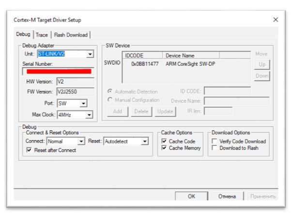
For convenience, you can configure the parameter responsible for ensuring that the MC is reset automatically after flashing. To do this, put a tick in the Reset and Run .
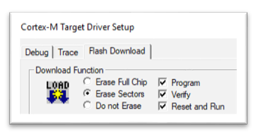
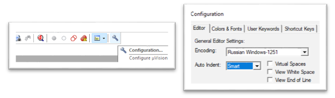
After that, you need to configure another option that will allow us to write Russian-language comments on the code of our projects. Click the Configuration button and in the opened menu in the Encoding field select Russian Windows-1251 .
Everything. Our IDE and programmer are ready to go!
Keil has a convenient project navigator, in which we can see the project structure, reference materials necessary for work, including those that we have already downloaded to our computer before (Discovery diagram, datasheet, reference manual), list functions used in the project and templates for quick insertion of different language constructs of a programming language.

Rename the folder in the project structure from Source Group 1 to App / User , thus denoting that we will have the user program files in this folder:

Add the main program file through the project navigator by running the Add New Item To Group “App / User” command.
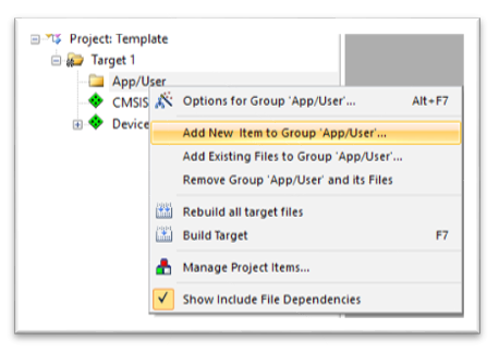
You need to select from the list of C File (.c) and assign it the name main.c :

The created file is automatically added to the project structure and opens in the main program window.
Well, now we can start creating our program.
First of all, you need to connect to our executable file the header document of our family of microcontrollers. Add the following lines to the main.c file; this program will make our LEDs blink alternately:
/* */ #include "stm32f0xx.h" /* */ int main(void) { /* GPIO */ RCC->AHBENR |= RCC_AHBENR_GPIOCEN; /* PC8 PC9 Output*/ GPIOC ->MODER = 0x50000; /* Output type Push-Pull */ GPIOC->OTYPER = 0; /* Low */ GPIOC->OSPEEDR = 0; while(1) { /* PC8, PC9 */ GPIOC->ODR = 0x100; for (int i=0; i<500000; i++){} // /* PC9, PC8 */ GPIOC->ODR = 0x200; for (int i=0; i<500000; i++){} // } }
, , . :

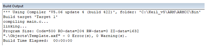
Build ( F7) , , :
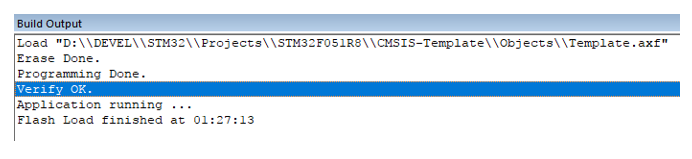
Load ( F8) :
, .
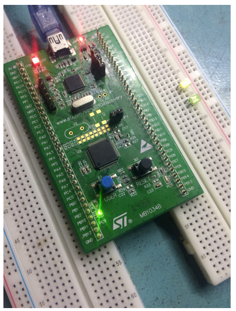
! STM32 ! , , , Discovery. )
:
All Articles