50 shades of stub *. Microcontrollers in switching power supplies. Part 3
DSC * - Peripheral Independent of the Core, also known as CIP - Core Independent Peripheral
Microcontrollers in switching power supplies. Part 1 .
Microcontrollers in switching power supplies. Part 2 .
Hardware reception of PWM-coded signals by Microchip microcontrollers
ADC and ADC with the Microchip microcontroller computer
Microchip Microcontroller I / O Ports
Configurable logic cells in PIC microcontrollers
Microcontrollers in switching power supplies
Part 3
In previous parts ( Part 1 , Part 2 ), we discussed how the Microchip Microcontroller-Independent Peripherals Peripherals allow building PWM controllers of switching power supplies from the building blocks by establishing connections between different peripheral modules. If new “building blocks” are added to the PWM controllers described above, then we will get new functions. Consider what can be done yet.
Automation of functions
Power unit protection
An important issue in power electronics is the provision of protective functions. If the feedback is violated, then there may be situations when the power switch will be open for an unacceptable time.
PIC microcontrollers with core-independent peripherals (CIP) have a timer with a Limit Timer (HLT) function.
Consider an example implementation of a PWM controller with automatic protection (limiting the width of the output pulse and the possibility of auto-shutdown).

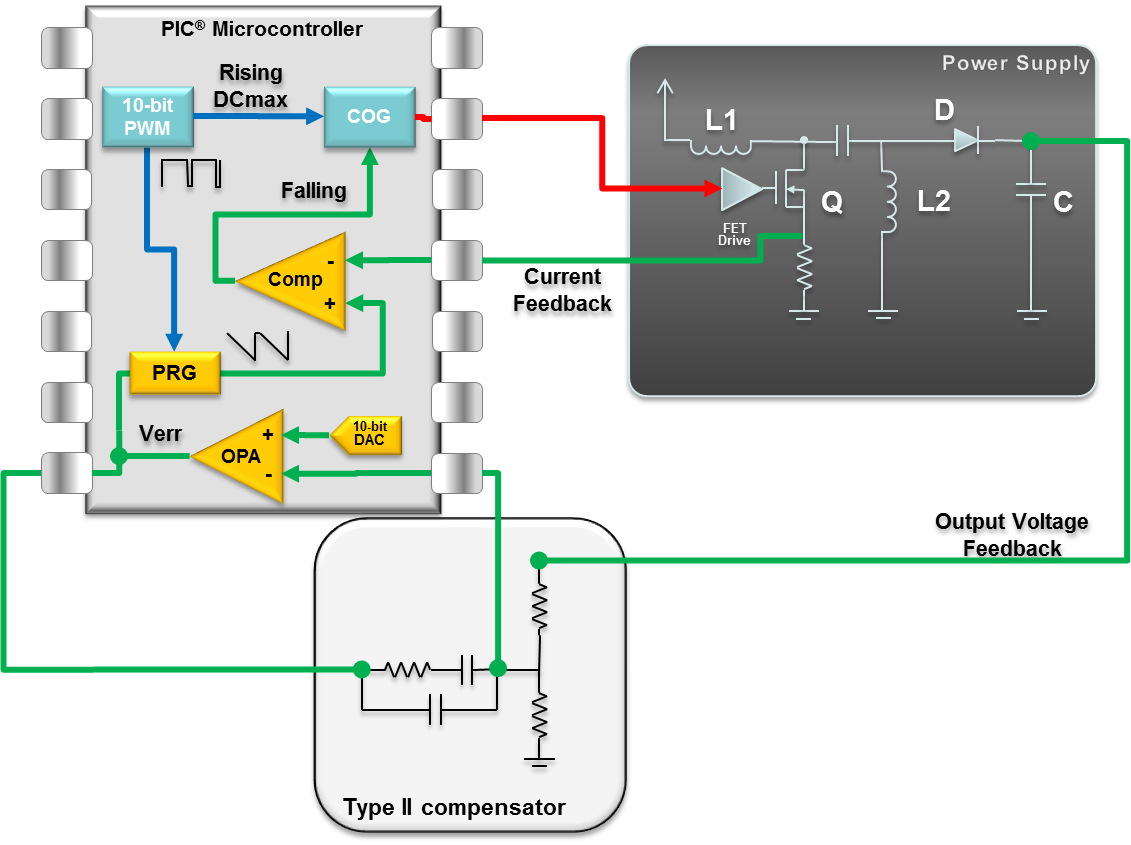
Fig. 3.1. PWM controller
Timer HLT1 - sets the time limit for the open state of the MOSFET, timer HLT2 - sets the off time Toff.
COG - Complementary Output Generator - form MOSFET control signals.
Algorithm (initialization of the microcontroller periphery):
- Timer HLT2 initiates the inclusion of COG (ie, power MOSFET) and cocks HLT1. The current through the inductance and the voltage on the Rsense is increasing. When the voltage coincides with Vref, the comparator is triggered.
- In normal mode, the comparator resets the COG, while the COG resets the HLT2 (Toff).
- The comparator signal is blanked for some time when the power switch is switched, thereby preventing false alarms that may arise from interfering interference (in Figure 3.1, the blanking signal is entered to the comparator for clarity, in fact, the blanking function is a feature of the COG module, it is not perceives the signal from the comparator).
Fig.3.2 explains the operation of such a PWM controller.
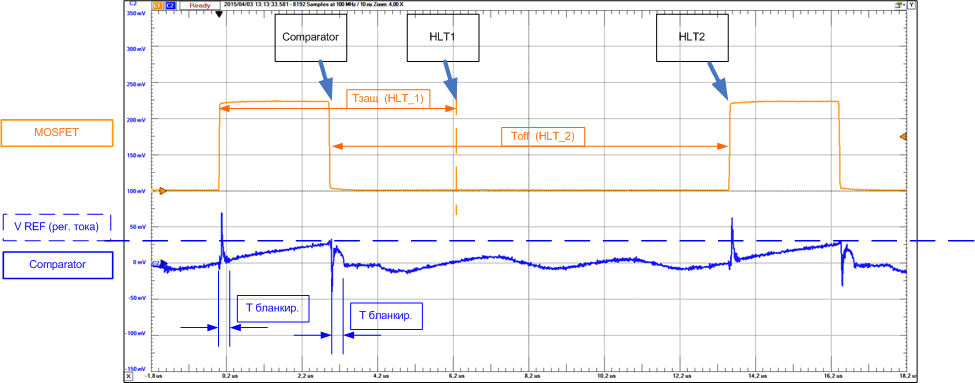
Fig.3.2. Voltage diagrams explaining the operation of the PWM controller (Fig. 3.1).
If the comparator does not work in Tzasch safety time, then the HLT1 limit timer will reset the COG and limit the open state of the power switch. A long key opening time can mean a break in the feedback, a fault in the power transistor or inductance.
The COG module has the function of blocking work, in this case the program can release the lock. This can be used for diagnostics - if the HLT1 is constantly triggered, the program can turn off the PWM controller and signal a malfunction.
Soft start
If energy remains in the inductance over the PWM period, over several periods this can lead to its saturation. At the same time, when the source starts, the output voltage is zero and the voltage feedback still does not work. Those. conditions are created for saturation of power inductance.
A soft start with voltage control can be provided by an increase in inductance or the formation of a low duty cycle at the start with a further increase in the duty cycle.
A soft start with current control can be realized by limiting the current of the feedback loop when the source is started.
Example: soft start with maximum current limit. DAC and comparator C2 limit the minimum peak current, the voltage of the DAC software slowly increases. When Vout reaches the norm, the C1 comparator starts working, by interrupting from which you can disconnect the soft start circuit and current limiting (DAC + Comp2).

Fig.3.3. PWM controller with soft start function.
Overvoltage protection
Adding the C2 comparator for analyzing the output voltage will help to turn off the COG module when the output voltage rises above the Over Voltage threshold (load interruption protection, see figure 3.4).
| Controller without protection | Controller with overvoltage protection at the output |
|---|---|
 |  |
Fig.3.4
Similarly, it is possible to organize protection against excess temperature, etc.
Maximum duty cycle limit
Previously, the implementation of such a function was considered in PWM controllers with voltage control, as well as an implementation option, see Figure 3.1.
In controllers with current control in normal mode, the output PWM is triggered by the front of the input PWM (reference), and is reset from the feedback signal - the current comparator. To limit the duty cycle of the output pulses, the reference PWM can be used, the duty cycle of which is selected as the maximum, for the developed IIP topology. Then, according to the decay of the reference PWM, it is possible to forcibly reset the COG module (see Fig. 3.5).

Fig.3.5. PWM controller with limiting of the duty cycle of the output pulses.
Internal Signal Access and Diagnostics
While Peripheral Independent of the Core forms the PWM controller of the pulse power supply and closes the feedback of the control loop, the core of the microcontroller allows measuring, diagnostic and communication functions. The microcontroller is capable of measuring peak and average current through inductance, a sawtooth compensation signal. Together with the measurement of time parameters, this allows the microcontroller core to perform mathematical calculations and obtain information that is not available through direct measurements.
Using the measured error voltage Verr, PRG and IL_min, it is possible to calculate the currents ILpeak and IL_avg.
Measurement of duty ratio and knowledge of IL_avg allows to calculate Iin_avg and Iout_avg. Using Vin, Vout, Iin_avg, Iout_avg, you can estimate the power and efficiency of the power source.
Communication interfaces allow external control, data transfer and diagnostic information. Software resources allow implementation of communication protocol stacks.
As an example, the microcontroller can be used in systems for generating power from alternative sources with storage batteries without the use of specialized energy converter circuits. For this kind of application, energy conversion and battery charge is controlled by a microcontroller. The search functions of the maximum energy point (MPPT) in solar converters and communication protocols are implemented in software. The user interface is implemented through the input / output ports of the microcontroller. Thus, the many functions of such a system can be implemented on one microcontroller (see Fig. 3.6), and not to apply several chips and microcircuits.

Fig.3.6.
The core-independent periphery allows for a number of other functions: limiting the current or turning off the source when overheating, changing the operating mode with intermittent current to the continuous current mode, etc., controlling the switching sequence of the second frequency amplifier, performing frequency jitter to offset the switching frequency and / or reducing (smearing) of the interference spectrum of the source.
Above, we considered the implementation of PWM controllers on the core-independent MK periphery for the implementation of single-stage or single-channel SMPS.
The PIC16F176x / 177x microcontroller families have up to 4 peripheral sets of the same type, each of which can be used to build an energy converter. Thus, the controllers of these families can be the core of multichannel or multistage SMPS and energy converters.
Microcontroller program
SMPS with implementation on the periphery independent of the core practically does not require intervention from the core of the microcontroller. The task of the microcontroller is reduced to the initial configuration of the periphery, after which the functions / modules operate autonomously by feedback signals. The controller may be required to take minimal part in processing and changing the interaction algorithm of the periphery, for example, when starting soft, changing the output parameters of the source, working out emergency modes, etc.
Therefore, the core and the microcontroller program can perform a number of inherent functions - control, provision of interface with control equipment, indication of modes, etc.
On the Microchip website, you can find an implementation of the PMbus, DALI, DMX interfaces, which are widely used in various systems with energy converters.
Debugging
To debug a system, it is not necessary to start with the layout of the power section. For some tasks, the resources and peripherals of the MC allow you to form both the logic of control of the converter and the emulation of the feedback signals of the output topology of the converter.
| topology | scheme |
|---|---|
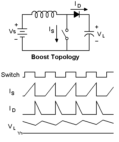 | 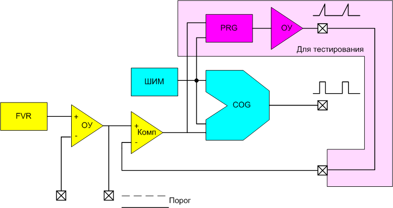 |
Fig.3.7. An example of the formation of a sawtooth signal, for debugging the PWM controller with the measurement of the peak current value.
| scheme | diagram |
|---|---|
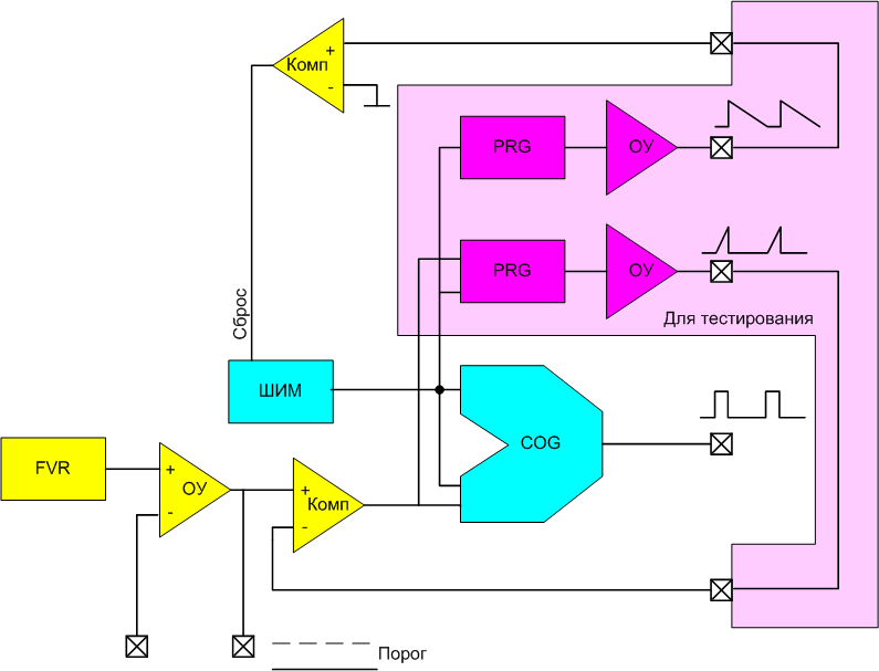 |  |
Fig.3.8. An example of the formation of sawtooth signals for debugging the PWM controller with the measurement of the peak current value and the detection of zero current in the inductance.
Results
The possibility of flexible configuration of the periphery allows you to use the same general-use MC in different tasks, including the creation of PWM controllers of energy converters.
The periphery independent of the core is interesting in and of itself, but the possibility of synthesizing functional blocks, i.e. sharing of several peripheral modules for solving specific tasks. In this case, the clock frequency, speed, and bit depth of the core go into the background - the hardware performs specialized functions, and the core deals with software support for the product.
Used and recommended literature for studying:
- Microchip web site: http://www.microchip.com/promo/dspic33-gs-digital-power
- Configurable logic cells in PIC microcontrollers https://geektimes.ru/post/278718/
- Microchip Microcontroller I / O Ports https://geektimes.ru/post/279374/
- TB3119. Complementary Output Generator Technical Brief. www.microchip.com
- Dynamics and Control of Switched Electronic Systems. Chapter 2. Pulse-Width Modulation http://www.springer.com/978-1-4471-2884-7
- TB3155. Multiphase Interleaved PWM Controller with Diode Emulation Using 8-Bit PIC Microcontrollers. www.microchip.com
- TB3153. Sample Functions Implemented with the Programmable Ramp Generator. www.microchip.com
- Keith Billings, Taylor Morey. SWITCHMODE POWER SUPPLY HANDBOOK
- Marty Brown. Power Supply Cookbook.
- AN2122. Flyback SMPS Using a Microcontroller as Control Unit. http://www.microchip.com
- 20097 PC7. Designing Intelligent Power Converters Using Core Independent Peripherals (CIPs)
Microchip MASTERs Training 2016. - AN2456. Configurability in a Switched Mode Power Supply Controller. http://www.microchip.com
All Articles