Reverse engineering DNA synthesizer
Just yesterday, I got a DNA synthesizer in my hands. The device solves the inverse problem compared to the DNA sequencer.
Moreover, this device itself, in fact - the system for supplying reagents to the sequencer. As soon as he came to my house, he was immediately taken apart. But first, briefly, how it works.
In this device, active nucleotides are fed to the reaction column, in the order given by the computer. Whatever they react with each other, their active group is blocked on the one hand. Between the nucleotide feeds, a special solution is fed into the column that unlocks the active end and makes it possible to attach the next nucleotide. Whatever the growing DNA does not wash away with the remnants of the reagents, it is fixed on a solid carrier in the column before synthesis.

The key element in the DNA synthesizer, besides the synthesis column, is a rotary valve, which allows you to switch the flow of reagents without mixing them. I hunted him. in nature, this valve costs about $ 1000. Well, the next element that there must necessarily be - the pump. But he is not very interesting to me, I already have a cheaper and inaccurate.
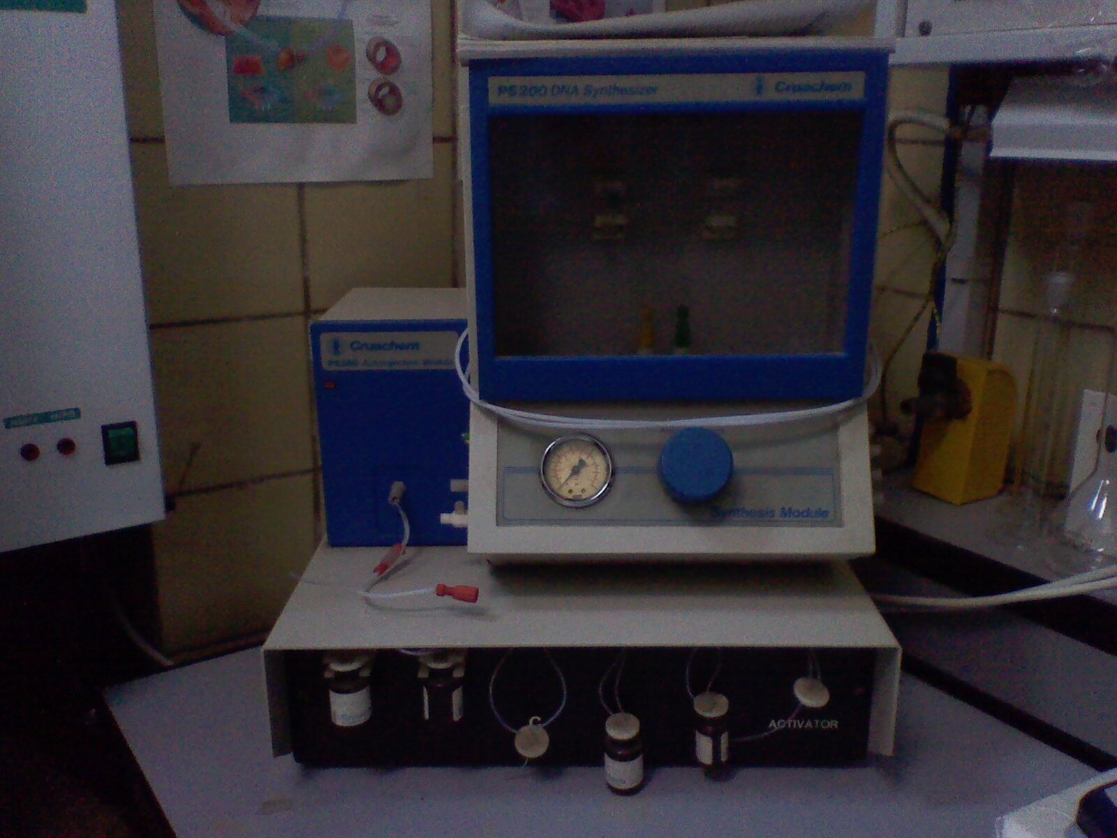
So, the figure shows the condition in which the device appeared before me. It consists of two blocks. Why are made separately, I still do not understand. 1993 device. All software was written under DOS and has long been lost. I was asked to restore the software under XP. This device contacted the computer through the LPT port, there is no documentation either, so it is not possible to restore the communication protocol with the computer using human methods. Therefore we take, and we throw out electronics from it. Replace it with arduino;)
Now take the screwdriver, disassemble it, and look inside:
First block:

Immediately we see the long-awaited rotary valve, injection module (in fact, the pump with accurate dosage) and the electronics that controls it. If you look better, it is clear that the rotary valve is controlled directly from the outside, bypassing the electronics.
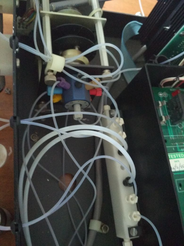
Of particular interest is the "pump" it consists of a 1: 2 valve, apparently, also a rotary valve, and a piston, which is driven by an electric drive. The valve connects the inlet to the piston, the piston moves to the desired distance, which is controlled by the optocoupler, the valve is turned into the piston-exit state, and the piston pushes the necessary dosage into the reactor. And this process is controlled by a bunch of electronics. Based on Intel's MK P8031AH
I was pleased with the “retro-style” tracks, which are all curved, as if the microwave were there.
Consider the hydraulic circuit of this unit.
Each tube with reagent includes two tubes. One by one, apparently, gas is pumped from the injection module, through the rotary valve, and pushes the reagent, which then enters the mixer, from which it then goes to the second unit.
Now disassemble the second block, the back wall:

Above, we see two stepper engines with gears, below is all the electronics, led by an 8-bit D70008AC-6MHz processor with a body kit of:
INS8154 N-Channel 128-by-8 Bit RAM Input / Output
TMS2516 16,384-BIT ERASABLE PROGRAMMABLE READ-only MEMORIES
Z8470AB1 - port controller
DS1488 - Quad Line Driver
DM74LS32 - Quad 2-Input OR Gate
DM74LS138 - Decoders / Demultiplexers
In the corner, lower right, a sticker on a chip with a DNA pattern. This is a memory chip, which stores software for the processor. It is read-only, and its erasure occurs by ultraviolet light through a transparent lid, which is sealed. Such is the specific "sealing" of the firmware.
The board below contains two more LPT port controllers and stepper motor drivers on the L293B.

Now remove the front cover:

To understand the scheme drawn fluids:
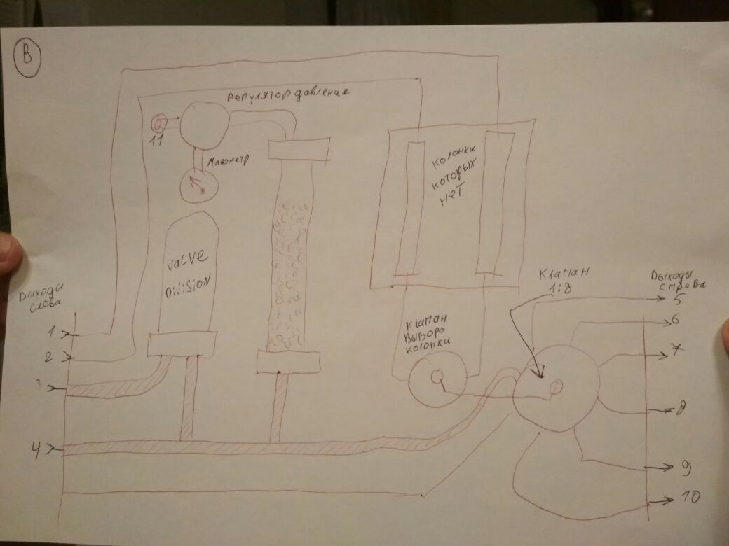
Here we see two more valves. One valve provides a choice of columns to which reagents will be supplied, since the device is two-channel. The second determines what exactly will be fed there from outside. All that is left, apparently, provides washing system. In fact, the pairing of two blocks with fluid is not very clear to me. Everything is complicated by the fact that the device is designed not only for DNA synthesis.
In general, my tasks:
Moreover, this device itself, in fact - the system for supplying reagents to the sequencer. As soon as he came to my house, he was immediately taken apart. But first, briefly, how it works.
In this device, active nucleotides are fed to the reaction column, in the order given by the computer. Whatever they react with each other, their active group is blocked on the one hand. Between the nucleotide feeds, a special solution is fed into the column that unlocks the active end and makes it possible to attach the next nucleotide. Whatever the growing DNA does not wash away with the remnants of the reagents, it is fixed on a solid carrier in the column before synthesis.
The key element in the DNA synthesizer, besides the synthesis column, is a rotary valve, which allows you to switch the flow of reagents without mixing them. I hunted him. in nature, this valve costs about $ 1000. Well, the next element that there must necessarily be - the pump. But he is not very interesting to me, I already have a cheaper and inaccurate.
So, the figure shows the condition in which the device appeared before me. It consists of two blocks. Why are made separately, I still do not understand. 1993 device. All software was written under DOS and has long been lost. I was asked to restore the software under XP. This device contacted the computer through the LPT port, there is no documentation either, so it is not possible to restore the communication protocol with the computer using human methods. Therefore we take, and we throw out electronics from it. Replace it with arduino;)
Now take the screwdriver, disassemble it, and look inside:
First block:
Immediately we see the long-awaited rotary valve, injection module (in fact, the pump with accurate dosage) and the electronics that controls it. If you look better, it is clear that the rotary valve is controlled directly from the outside, bypassing the electronics.
Of particular interest is the "pump" it consists of a 1: 2 valve, apparently, also a rotary valve, and a piston, which is driven by an electric drive. The valve connects the inlet to the piston, the piston moves to the desired distance, which is controlled by the optocoupler, the valve is turned into the piston-exit state, and the piston pushes the necessary dosage into the reactor. And this process is controlled by a bunch of electronics. Based on Intel's MK P8031AH
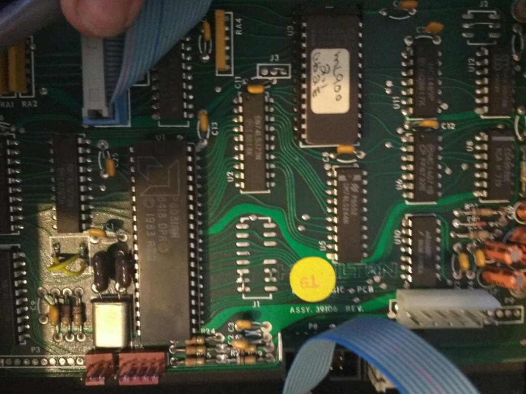
I was pleased with the “retro-style” tracks, which are all curved, as if the microwave were there.
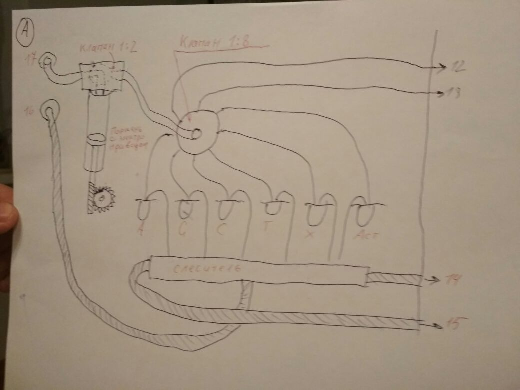
Consider the hydraulic circuit of this unit.
Each tube with reagent includes two tubes. One by one, apparently, gas is pumped from the injection module, through the rotary valve, and pushes the reagent, which then enters the mixer, from which it then goes to the second unit.
Now disassemble the second block, the back wall:
Above, we see two stepper engines with gears, below is all the electronics, led by an 8-bit D70008AC-6MHz processor with a body kit of:
INS8154 N-Channel 128-by-8 Bit RAM Input / Output
TMS2516 16,384-BIT ERASABLE PROGRAMMABLE READ-only MEMORIES
Z8470AB1 - port controller
DS1488 - Quad Line Driver
DM74LS32 - Quad 2-Input OR Gate
DM74LS138 - Decoders / Demultiplexers
In the corner, lower right, a sticker on a chip with a DNA pattern. This is a memory chip, which stores software for the processor. It is read-only, and its erasure occurs by ultraviolet light through a transparent lid, which is sealed. Such is the specific "sealing" of the firmware.
The board below contains two more LPT port controllers and stepper motor drivers on the L293B.
Now remove the front cover:
To understand the scheme drawn fluids:
Here we see two more valves. One valve provides a choice of columns to which reagents will be supplied, since the device is two-channel. The second determines what exactly will be fed there from outside. All that is left, apparently, provides washing system. In fact, the pairing of two blocks with fluid is not very clear to me. Everything is complicated by the fact that the device is designed not only for DNA synthesis.
In general, my tasks:
- Copy rotary valve; make it the reagent supply system for my sequencer. The idea was born: in my sequencer, to combine a DNA synthesizer. The main cost of the synthesizer is in this valve. If you can copy it, you can sell cheap DNA synthesizers.
- Replace electronics with arduino, c drivers for stepper motors and software. Each engine also has an optocoupler or encoder. I think there are a lot of people who want to help me with this.
- Start the device itself. To do this, it is necessary to understand its device, fluid connection, operation algorithms, find or make suitable reaction columns and reagents. I suggest to all sympathizers to write suggestions and ideas on this on my site .
All Articles