Automatic switch antennas with control on the MK
In amateur radio practice, sometimes there is a need to do something on a microcontroller. If you do not do this kind of crafts all the time, then you have to google the necessary schematic solution and the appropriate libraries for MCs for a long time, allowing you to quickly solve the problem. Recently, I wanted to make an automatic antenna switch. In the process, I had to use many of the capabilities of the Atmega MK in one compact project. Those who begin to study AVR, switch from arduino or occasionally program MK, pieces of code used by me in the project can be useful.
The antenna switch was conceived by me as a device that automatically connects the antenna to the transceiver, which is best suited for the working range of short waves. I have two antennas: Inverted V and Ground Plane, they are connected to the antenna tuner MFJ, in which they can be switched remotely. There is a branded manual switch MFJ, which I wanted to replace.
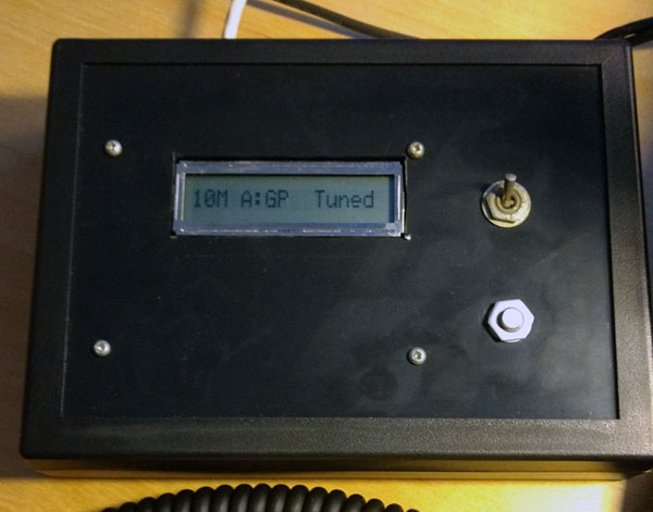
For the rapid switching of antennas to the MK one button is connected. I adapted it to memorize the preferred antenna for each band: when the button is pressed for more than 3 seconds, the selected antenna is memorized and selected correctly automatically after the next power-up of the device. Information about the current range, the selected antenna and the status of its tuning is displayed on a single-line LCD display.
You can find out in which range the transceiver operates in various ways: you can measure the signal frequency, you can get data via the CAT interface, but the easiest thing for me is to use the YAESU interface to connect an external amplifier. It has 4 signal lines, in binary code indicating the current range. They give a logical signal from 0 to 5 volts and they can be connected to the legs of the MK via a pair of terminating resistors.
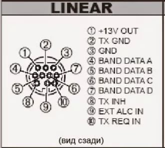
That's not all. In the transfer mode, the PTT and ALC signals are transmitted via the same interface. This is a logical signal to turn on the transmitter (pulling to the ground) and an analog signal from 0 to -4 V on the operation of the automatic power control system of the transmitter. I also decided to measure it and display it on the LCD in transmission mode.
In addition, the MFJ tuner is able to transmit signals to the remote control that it is tuning and that the antenna is tuned. For this purpose, two control LEDs are provided on the original MFJ console. Instead of the LEDs, I connected optocouplers and gave them a signal to the MK, so that all the information can be seen on one display. Looks like a ready device.
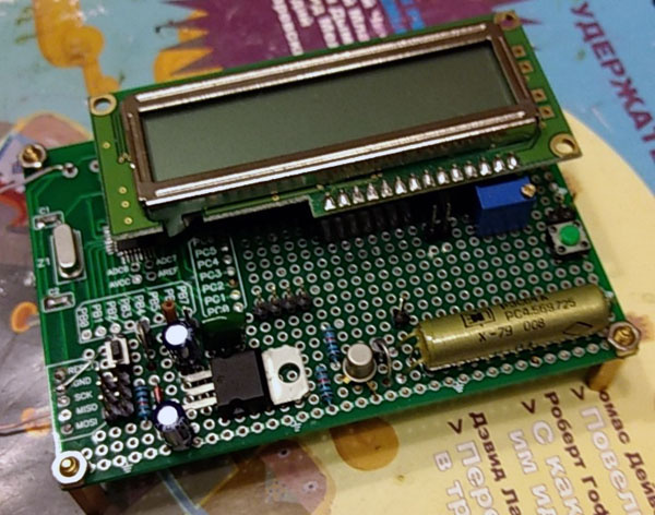
Briefly about homemade like everything. Now about the software part. The code is written in Atmel Studio (Freely downloaded from the Atmel website). The project for beginners demonstrates the following possibilities for using the popular Atmega8 MC:
- Button connection
- Connect line input for digital signal from transceiver and tuner
- Connect the control output of the antenna switching relay
- Connecting a single-line LCD display
- Connecting the buzzer and audio output
- Connecting the analog input line ADC and voltage measurement
- Using interrupts
- Using the timer to count down the time the button is pressed
- Use watchdog timer
- Using non-volatile memory to store selected antennas
- Using UART for debug printing
- Saving energy in a simple MK
So, let's begin. In the course of the text will meet all the names of registers and constants, peculiar to the applicable MK. This is not arduino, here unfortunately, you will have to read datashit on MK. Otherwise, you do not understand what all these registers mean and how you can change their values. But the structure of the program as a whole will remain the same.
First of all we connect to the MK button
This is the easiest. One contact is connected to the foot of the MK, the second contact of the button is on the ground. For the button to work, you will need to turn on the pull-up resistor in the MC. It connects the button through the resistance to the + 5V bus. Make it quite simple:
PORTB |= (1 << PB2); // pullup resistor
Similarly, all digital inputs are controlled to the + 5V bus, which are controlled by a ground fault (optocouplers, signal lines from the transceiver, PTT signal). Sometimes it is better to physically solder such a resistor of a smaller naminal (for example, 10k) between the MK input and the + 5V bus, but discussing this issue is beyond the scope of the article. Since all input signals in a project rarely change values, they are shunted to ground with 10 nanofarad capacitors to protect against interference.
Now we have logical 1 at the input of PB2, and when we press the button, we will have a logical 0. When we press / release, we need to track the button contact bounce, checking that the signal level has not changed over time, say 50 milliseconds. This is done in the program as follows:
if(!(PINB&(1<<PINB2)) && !timer_on) { // _delay_ms(50); if( !(PINB&(1<<PINB2)) ) { // - passed_secs = 0; timer_on = 1; } }
Now we connect the squeaker
It will give a confirmation tone that the antenna is recorded in the memory of the MC. Pischalka is just a piezo element. It connects through a small resistance to the foot of the MK, and the second contact to + 5V. For the operation of this buzzer, you must first configure the MK's foot to output data.
void init_buzzer(void) { PORTB &= ~(1 << PB0); // buzzer DDRB |= (1 << PB0); // output PORTB &= ~(1 << PB0); }
Now you can use it. For this, a small function was written using time delays to switch the legs of the MK from 0 to 1 and back. Switching with the necessary delays allows the output of the MC to produce an audio signal of 4 kHz with a duration of about a quarter of a second, which is voiced by the piezoelectric element.
void buzz(void) { // 4 0,25 for(int i=0; i<1000; i++) { wdt_reset(); // PORTB |= (1 << PB0); _delay_us(125); PORTB &= ~(1 << PB0); _delay_us(125); } }
For the work of the delay functions do not forget to connect the header file and set the processor speed constant. It is equal to the frequency of the quartz resonator connected to the MC. In my case it was quartz at 16 MHz.
#ifndef F_CPU # define F_CPU 16000000UL #endif #include <util/delay.h>
We connect to the MK relay switching antennas
Here you just need to adjust the leg MK to work out. To this leg, through a amplifying transistor, a reed switch is connected in a standard pattern.
void init_tuner_relay(void) { PORTB &= ~(1 << PB1); // relay DDRB |= (1 << PB1); // output PORTB &= ~(1 << PB1); }
Display connection
I used a single line 16 character LCD display 1601, extracted from old equipment. It uses the well-known HD44780 controller, to control which a lot of libraries are available on the network. Some kind person wrote a light display control library, which I used in the project. Setting up the library is reduced to specifying in the header file HD44780_Config.h the numbers of the legs of the ICs connected to the desired display pins. I applied a display connection over 4 data lines.
#define Data_Length 0 #define NumberOfLines 1 #define Font 1 #define PORT_Strob_Signal_E PORTC #define PIN_Strob_Signal_E 5 #define PORT_Strob_Signal_RS PORTC #define PIN_Strob_Signal_RS 4 #define PORT_bus_4 PORTC #define PIN_bus_4 0 #define PORT_bus_5 PORTC #define PIN_bus_5 1 #define PORT_bus_6 PORTC #define PIN_bus_6 2 #define PORT_bus_7 PORTC #define PIN_bus_7 3
A feature of my display instance was that one line on the screen was displayed as two lines of 8 characters each, so the program made an intermediate screen buffer for more convenient work with the screen.
void init_display(void) { PORTC &= ~(1 << PC0); // display DDRC |= (1 << PC0); // output PORTC &= ~(1 << PC0); PORTC &= ~(1 << PC1); // display DDRC |= (1 << PC1); // output PORTC &= ~(1 << PC1); PORTC &= ~(1 << PC2); // display DDRC |= (1 << PC2); // output PORTC &= ~(1 << PC2); PORTC &= ~(1 << PC3); // display DDRC |= (1 << PC3); // output PORTC &= ~(1 << PC3); PORTC &= ~(1 << PC4); // display DDRC |= (1 << PC4); // output PORTC &= ~(1 << PC4); PORTC &= ~(1 << PC5); // display DDRC |= (1 << PC5); // output PORTC &= ~(1 << PC5); LCD_Init(); LCD_DisplEnable_CursOnOffBlink(1,0,0); } /* 16 0-3 40M 4-8 A:GP A:IV 9-15 : TUNING=, TUNED==, HI-SWR= */ uchar display_buffer[]={' ',' ',' ',' ',' ',' ',' ',' ',' ',' ',' ',' ',' ',' ',' ',' '}; // 16 void update_display() { LCD_Init(); LCD_DisplEnable_CursOnOffBlink(1,0,0); // 16 8 LCD for (uchar i=0; i<8; i++){ LCD_Show(display_buffer[i],1,i); LCD_Show(display_buffer[i+8],2,i); } }
The update_display () function allows you to display the contents of the buffer on the screen. The byte values in the buffer are the ASCII codes of the output characters.
Output debug print to COM port
MK has a UART and I used it to debug the program. When connecting a MK to a computer, you only need to remember that the signal levels at the output of the MK are in the TTL standard, not RS232, so you will need a simple adapter. I used a usb serial adapter similar fully on aliexpress. Any terminal program, for example from arduino, is suitable for reading data. UART port setup code:
#define BAUD 9600 #include <stdio.h> #include <stdlib.h> #include <avr/io.h> // UART RS232 void uart_init( void ) { /* // UBRRH = 0; UBRRL = 103; //9600 16 */ #include <util/setbaud.h> UBRRH = UBRRH_VALUE; UBRRL = UBRRL_VALUE; #if USE_2X UCSRA |= (1 << U2X); #else UCSRA &= ~(1 << U2X); #endif //8 , 1 , UCSRC = ( 1 << URSEL ) | ( 1 << UCSZ1 ) | ( 1 << UCSZ0 ); // // UCSRB = ( 1 << TXEN ) | ( 1 <<RXEN ); UCSRB = ( 1 << TXEN ); } int uart_putc( char c, FILE *file ) { // while( ( UCSRA & ( 1 << UDRE ) ) == 0 ); UDR = c; wdt_reset(); return 0; } FILE uart_stream = FDEV_SETUP_STREAM( uart_putc, NULL, _FDEV_SETUP_WRITE ); stdout = &uart_stream;
After setting up the output stream, you can use regular printf to print to the port:
printf( "Start flag after reset = %u\r\n", mcusr_mirror );
The program uses the printing of real numbers. Regular libraries do not support this output mode, so I had to connect a full library when linking the project. It, however, seriously increases the amount of code, but I had a large amount of memory, so it was uncritical. In the linker options you need to specify the line:
-Wl,-u,vfprintf -lprintf_flt
Work with timer and interrupts
To count the time intervals in the program, it is important to have a time counter. It is needed to track that the button is pressed for more than 3 seconds and, therefore, you need to memorize new settings in non-volatile memory. To measure the time in AVR style, you need to configure the pulse generator clock and interrupt, which will be performed when the counter reaches the specified value. I set the timer so that it gives an interrupt about once a second. In the interrupt handler itself, the number of elapsed seconds is counted. The timer_on variable controls the on / off timer. It is important not to forget to declare all variables that are updated in the interrupt handler as volatile, otherwise the compiler can “optimize” them and the program will not work.
// 1 - void timer1_init( void ) { TCCR1A = 0; // 1 - /* 16000000 / 1024 = 15625 , 15625 1 */ // CTC, ICP1 interrupt sense (falling)(not used) + prescale /1024 + (not used) TCCR1B = (0 << WGM13) | (1 << WGM12) | (0 << ICES1) | ((1 << CS12) | (0 << CS11) | (1 << CS10)) | (0 << ICNC1); OCR1A = 15625; // TIMSK |= (1 << OCIE1A); } uchar timer_on = 0; volatile uchar passed_secs = 0; // e ISR(TIMER1_COMPA_vect) { if (timer_on) passed_secs++; }
The value of the variable passed_secs is checked in the main program loop. When the button is pressed, the timer starts and further in the main program loop the timer value is checked while the button is pressed. If this value exceeds 3 seconds, it writes to the EEPROM, and the timer stops.
Last, but most importantly, after all initializations, you must enable execution of interrupts with the sei () command.
ALC level measurement
Produced using an integrated analog-to-digital converter (ADC). I measured the voltage at the ADC7 input. We must remember that you can measure the value from 0 to 2.5V. and my input voltage was from -4V to 0V. Therefore, I connected the MK through the simplest voltage divider at the resistors, so that the voltage level at the MK input was at the specified level. Further, I did not need high accuracy, so I applied an 8-bit conversion (you only need to read data from the ADCH register). As a reference source, I used an internal ION of 2.56V, which slightly simplifies calculations. For ADC operation, do not forget to connect a 0.1 µF capacitor to the ground to the ground REF.
The ADC in my case runs continuously, reporting the end of the conversion by calling the interrupt ADC_vect. It is a good idea to average the values of several conversion cycles to reduce the error. In my case, I derive an average of 2500 transformations. All the code for working with ADC looks like this:
// ALC #define SAMPLES 2500 // #define REFERENCEV 2.56 // #define DIVIDER 2.0 double realV = 0; // ALC double current_realV = 0; volatile int sampleCount = 0; volatile unsigned long tempVoltage = 0; // volatile unsigned long sumVoltage = 0; // void ADC_init() // ADC7 { // 2,56, 8 bit - ADCH ADMUX = (1 << REFS0) | (1 << REFS1) | (1 << ADLAR) | (0 << MUX3) | (1 << MUX2) | (1 << MUX1) | (1 << MUX0); // ADC7 // , free running, ADCSRA = (1 << ADEN) | (1 << ADFR) | (1 << ADIE) | (1 << ADPS2) | (1 << ADPS1) | (1 << ADPS0); // 128 ADCSRA |= (1 << ADSC); // Start ADC Conversion } ISR(ADC_vect) // 2500 { if (sampleCount++) // tempVoltage += ADCH; if (sampleCount >= SAMPLES) { sampleCount = 0; sumVoltage = tempVoltage; tempVoltage = 0; } ADCSRA |=(1 << ADIF); // Acknowledge the ADC Interrupt Flag } realV = -1.0*(DIVIDER * ((sumVoltage * REFERENCEV) / 256) / SAMPLES - 5.0); // ALC if (realV < 0.0) realV = 0.0; printf("ALC= -%4.2f\r\n", realV); //
Using EEPROM
This is non-volatile memory in MK. It is convenient to use it for storing any settings, correction values, etc. In our case, it is used only to store the selected antenna for the desired range. To this end, a 16 byte array is allocated in the EEPROM. But you can access it through special functions defined in the avr / eeprom.h header file. When launched, the MC reads information about the saved settings into the RAM and turns on the required antenna depending on the current range. With a long press on the button, a new value is recorded in the memory, followed by a beep. When writing to the EEPROM, just in case, interrupts are prohibited. Memory initialization code:
EEMEM unsigned char ee_bands[16]; // unsigned char avr_bands[16]; void EEPROM_init(void) { for(int i=0; i<16; i++) { avr_bands[i] = eeprom_read_byte(&ee_bands[i]); if (avr_bands[i] > 1) avr_bands[i] = ANT_IV; // EEPROM , FF } }
Fragment of the processing code for pressing the button for 3 seconds and writing to memory:
if (!(PINB&(1<<PINB2)) && passed_secs >= 3) { // 3 timer_on = 0; // read_ant = avr_bands[read_band]; // cli(); EEPROM_init(); // sei(); if (read_ant) { avr_bands[read_band] = ANT_GP; } else { avr_bands[read_band] = ANT_IV; } cli(); eeprom_write_byte(&ee_bands[read_band], avr_bands[read_band]); // EEPROM sei(); buzz(); }
Use watchdog timer
It is no secret that in conditions of strong electromagnetic interference, the MC can hang. When the radio works, there are such interferences that “the irons start to talk”, so you need to ensure a careful reset of the MC in case of a hang. This purpose serves as a watchdog timer. It is very easy to use. First, connect the avr / wdt.h header file to the project. At the beginning of the program after all the settings have been completed, you need to start the timer by calling the function wdt_enable (WDTO_2S), and then do not forget to periodically reset it with the call to wdt_reset (), otherwise it will restart the MC itself. For debugging, in order to find out for what reason MK was restarted, you can use the value of the special register MCUSR, the value of which can be memorized and then issued to the debug print.
// // uint8_t mcusr_mirror __attribute__ ((section (".noinit"))); void get_mcusr(void) \ __attribute__((naked)) \ __attribute__((section(".init3"))); void get_mcusr(void) { mcusr_mirror = MCUSR; MCUSR = 0; wdt_disable(); } printf( "Start flag after reset = %u\r\n", mcusr_mirror );
Saving energy for lovers of ecology
While MK is not busy with anything, he can fall asleep and wait for the next interruption to occur. In this case, some electrical energy is saved. Trifle, but why not use it in the project. Especially since it is very simple. Include the avr / sleep.h header file. The program body consists of one infinite loop, in which you need to call the sleep_cpu () function, after which the MC falls asleep and the main loop stops until the next interrupt occurs. They occur when the timer and ADC work, so the MK will not sleep for a long time. Hibernation mode is determined when MC is initialized by calling two functions:
set_sleep_mode(SLEEP_MODE_IDLE); // IDLE sleep_enable();
That's all for now. The switch I made, he successfully works on my amateur radio station without fail. I hope the material provided will be useful for beginners.
73 de R2AJP
All Articles