50 shades of stub *. Microcontrollers in switching power supplies. Part 2
DSC * - Peripheral Independent of the Core, also known as CIP - Core Independent Peripheral
Microcontrollers in switching power supplies
Part 2
In the previous part of the article , a version of building a “typical” PWM controller of a Pulsed Power Supply (SMPS), variants of PWM controller based on PSN and some topologies of the SMPS was considered.
We will continue our acquaintance with the capabilities of the Periphery Independent of the Core as applied to the task of building switching power supplies.
Synchronous converter
If the output voltage is low enough and becomes commensurate with the fall on the diode, then the efficiency of the source drops significantly. To improve the parameters of the SMPS, the diode can be replaced by a MOSFET, the voltage drop on which is significantly lower than on the live diode. We get a synchronous converter.
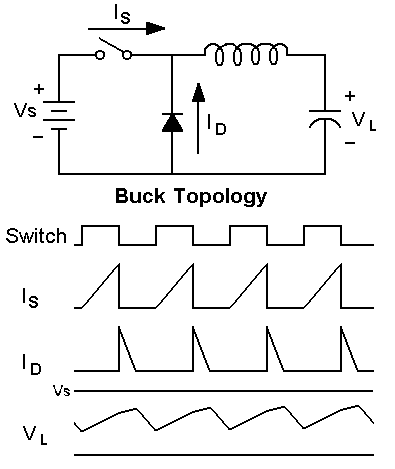
Fig. 2.1.a. Down converter

Fig. 2.1.b. Step down converter
A peripheral module for generating complementary output signals (Complimentary Output Generator, COG) is used to form two antiphase PWM signals.
Complementary signal generator
allows you to control the period and duty cycle of one or two complementary outputs using two input signal sources. Together with the ability to control key parameters such as dead time, blanking, phase, polarity, auto-shutdown and auto-recovery, the COG module provides a powerful tool for building a PWM controller core. The complementary signal generator in 8-bit Microchip microcontrollers is completely autonomous and, in general, does not require the intervention of the MK core. For a more detailed acquaintance with COG, I recommend contacting the technical description TB3119 [4].
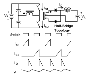
The COG module is somewhat similar to the SR trigger, it also has setup and reset inputs, but operating on events (Rising Event and Falling Event). Events are recorded both on the fronts / decays and on the levels of the selected input signals. Input signals can be both external (input ports) and internal (timers, PWM, comparators, configurable logic cells, etc.). The outputs of the generator of complementary signals are able to work in various modes: half bridge, full bridge, push-pull, PWM. Output signals are formed taking into account the meter time, blanking, phase delay and polarity. As a rule, the output ports of the COG module have an increased load capacity (50-100mA).
To protect the output power stages, there are tripping inputs, on events at which the module outputs are transferred to a safe state (0, 1 or 3rd state). If the alarm signal disappears, the module can be automatically turned on or program intervention is required.
The COG module allows the use of topologies with a transformer, which are commonly used for galvanically isolated SMPS.
When building converters using transformers, voltage and current control modes with proportional or hysteresis control are also used, i.e. all the same that was considered earlier in the first part of the article.
 |  |
 |  |
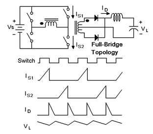 | 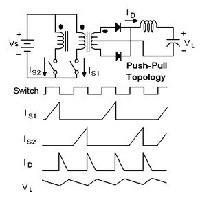 |
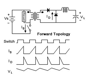
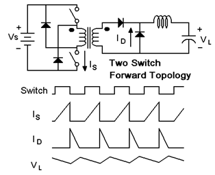
Fig. 2.2. Topologies of IIP with transformers

Fig.2.3. Voltage control mode with hysteresis control. Option with fixed and adjustable output voltage.

Fig. 2.4. Hysteresis Control Current Mode

Fig. 2.5. Current control mode with proportional control.
Multi-phase alternating PWM control
In multiphase converters, interleaved mode of operation is often used, in which the current separation between several identical topologies connected in parallel is used. Such a topology allows obtaining more efficient filtering (less current ripple), reducing the size of the source (less filter), and increasing efficiency.
The interleaved converter consists of several identical channels, the inputs and outputs of which are combined, but the control phases of such converters are shifted by 360 ° / n, where n is the number of phases.
For a two-phase alternating upconverter, the two channels work in antiphase - two PWM signals are shifted by 180 ° relative to each other.
A simplified diagram is shown in Fig. 2.6. [five]. The keys S1 and S2 open alternately. When key S1 is open, S2 is closed, L1 is charged, and L2 gives up previously accumulated energy to the load. Further channels alternate.

Figure 2.6. An illustration of the principle of operation of an interleaved switching power supply.
Below is a diagram of a two-phase synchronous alternating step-up converter [6].
The converter operates by monitoring the peak current with one common voltage feedback loop, which provides control of two independent current loops. The controller provides current balancing between phases, protection against short circuits and low ripple during transitions between continuous and intermittent conductance.
For synchronous rectification, additional measures are necessary to prevent current from flowing back to the input when the inductance stops discharging in the discontinuous conduction mode (DCM). The top key of the synchronous converter must be turned off when the current in the inductance becomes zero.

Fig.2.7. Two-phase interleave synchronous boost
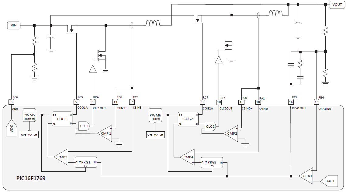
Fig.2.8. Two-phase Interlaced Synchronous Down Converter
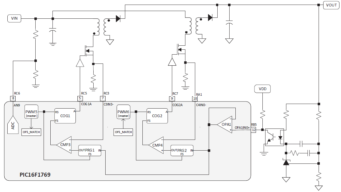
Fig.2.9. Two-phase interleave flyback converter

Fig.2.10. Two Phase Intermediate Straight Converter
Details of various options for Interleaved PIC based on PIC microcontrollers are given in TB3155 [6].
Variable frequency control
In the previous examples, the PWM start frequency is set by the timer, i.e. implemented control with a fixed frequency of PWM.
The method of control with a fixed frequency will lose efficiency at low loads, as it has a fixed loss in the key. Since we are considering solutions on a microcontroller, we can easily provide a variable switching frequency depending on the load current and the operating mode of the converter.
In a controller with a fixed PWM frequency, the discontinuous current mode is most easily realized when no current flows through any element of the converter.

Fig.2.11. Intermittent current mode.
Peripheral Independent of the core can assist in the implementation of the critical conductivity mode, when the achievement of a current to zero is monitored. In this case, the PWM controller automatically changes the switching frequency to be in the critical conductivity mode.

Fig.2.12. The mode of critical conduction current.
Configurable peripherals allow you to implement other algorithms: if you make a comparator signal to reset the timer, you can implement control with a fixed off time (Fixed Off Time) or a fixed turn-on time (Fixed On Time or Constant On Time).
Control with a fixed on-time allows building an SMPS with a power corrector [7].
 | 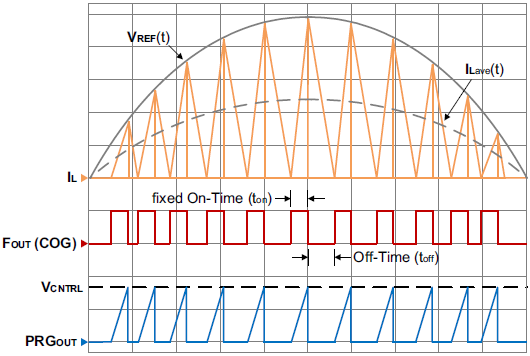 |
Fig.2.13. Voltage controlled PWM controller in a configuration with a fixed on-time (COT) in the critical conductivity mode.
So, we considered some topologies of IIP. All the necessary peripherals for the implementation of PWM controllers are contained in PIC16F176x series microcontrollers. We can implement any of the described topologies on the periphery independent of the core, i.e. the operation of the described PWM controllers does not depend on the speed of the core.
To be continued...
[4] TB3119. Complementary Output Generator Technical Brief. www.microchip.com
[5] Dynamics and Control of Switched Electronic Systems. Chapter 2. Pulse-Width Modulation http://www.springer.com/978-1-4471-2884-7
[6] TB3155. Multiphase Interleaved PWM Controller with Diode Emulation Using 8-Bit PIC Microcontrollers. www.microchip.com
[7] TB3153. Sample Functions Implemented with the Programmable Ramp Generator. www.microchip.com
All Articles