Router with VoIP functions for only one hundred square meters.
Under the cat we will talk about the device, combining the functions of an optical wireless router with VoIP, which can work as a gateway.
The LR-2G211 is a CPE router oriented for FTTB / FTTH solutions with a gigabit SFP interface and analog interfaces. Out of the box, the router has all the necessary L2 / L3 functionality for solving everyday tasks in home or small business.
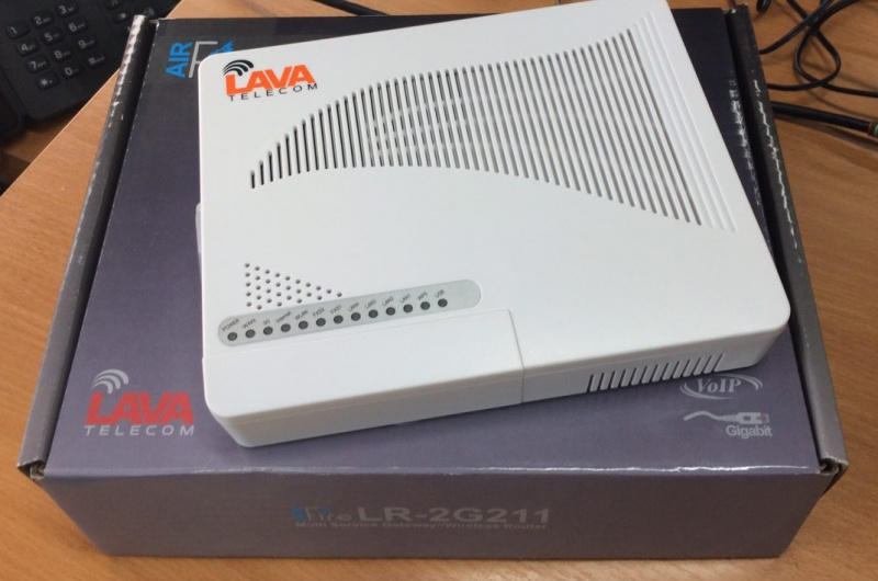
Packaging
The package is a cardboard box with a glossy finish and an image of the router and a typical device connection scheme.


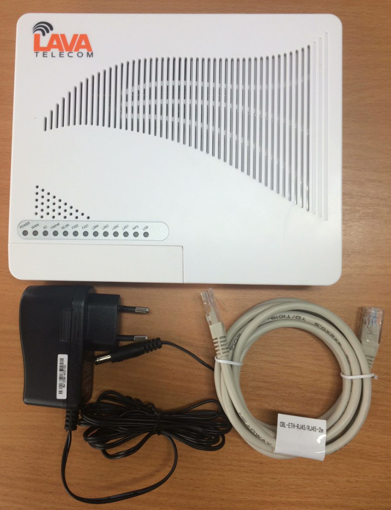
Equipment
Nothing superfluous: the LR-2G211 router itself, a two-meter patchcord and a 12V1A power supply unit. There is no documentation in the delivery set, but it is available via the link.
The router is made of white and fairly strong plastic. On the lid and on the sides of the case there is a perforation for air circulation.

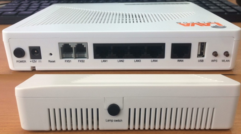
On the case there are control keys:
- Lamp switch - on / off all LEDs on the device;
- Power - power router on / off;
- WPS - for quick connection to the device;
- WLAN - on / off wireless interface.
The router is equipped with two FXS ports, four LAN ports, one combo WAN (RJ45 + SFP in a special closed "compartment") and a USB port for connecting a modem.
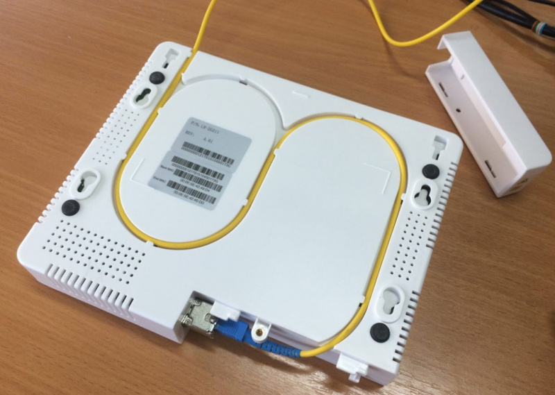
At the side of the router there is a cover for accessing the optical SFP interface, which can be used to connect to the optical network.

LR-2G211 has a light indication indicating the activity of the device:
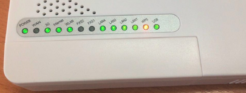
Vnutryanka

Visually, the soldering is done quite neatly, there are no flux residues, the components sit quite smoothly. The router is based on the Marvell 88F6550 SoC processor, which is tightly closed by a radiator, has two Gigabit interfaces onboard, 1xLAN (RJ45), 1xComboWAN (SFP + RJ45) and 3xLAN 100 Mbps (RJ45).
The LR-2G211 is equipped with two omnidirectional Airgain N2430GNS antennas (blue in the photo), which are spaced so as to avoid collisions during operation of the wireless network. Antenna Characteristics:

The router’s wireless interface is based on the RTL8192CE chip with support for 802.11b / g / n and MIMO2x2 standards. On board also has a USB 2.0 port with support for 3G / 4G USB modem.
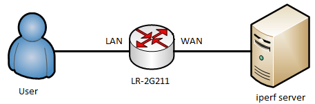
Forwarding results with different packet sizes
The performance test was performed according to the LAN-WAN scheme (via NAT) using iperf, i.e. On the client side, the iperf client is deployed, on the server side, behind the WAN, back - the iperf server. Performance test with copper 100Mbps LAN1-3 ports rests on port speed. When testing with 1000Mbps LAN4, the following results are obtained:

Wiring diagram
LR-2G211 is most relevant in cases where a telecom operator provides three services at once through a single cable: high-speed Internet access, cable television and IP telephony.
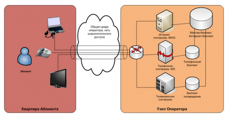
For example, we will use the legend according to which the user has an IPoE connection, and the services are presented in separate VLANs, for example, 100 (SIP) and 200 (VOIP).
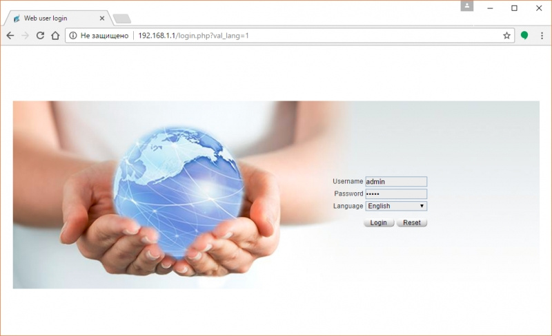
After connecting the computer to the router, the web-based control interface is accessible by factory details.
By default, the router has an IP address: 192.168.1.1
Login / password for access to the web interface: admin / admin
The start page contains all the basic information about the router, such as:
- firmware version,
- device model
- serial number,
- working hours,
- network details
- download schedules.

There are several menu tabs available in the user interface:
- Device - contains information about the device;
- Quick Guide - router quick setup menu;
- Basic - the basic configuration;
- VoIP - a menu for working with telephony services;
- Security - menu for access to the built-in protection mechanisms;
- System - menu for diagnostics, updates, reloads, etc.
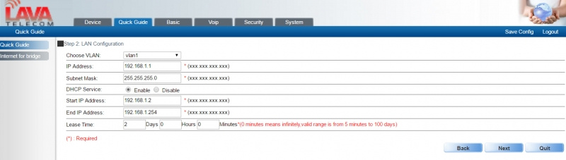
Quick Setup feature (Quick Guide), which will help you quickly and easily configure the router to work on the network.


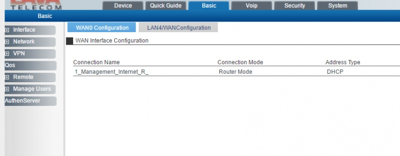
To access the advanced configuration, go to the Basic menu. The general menu looks like this:
Interface for IPoE
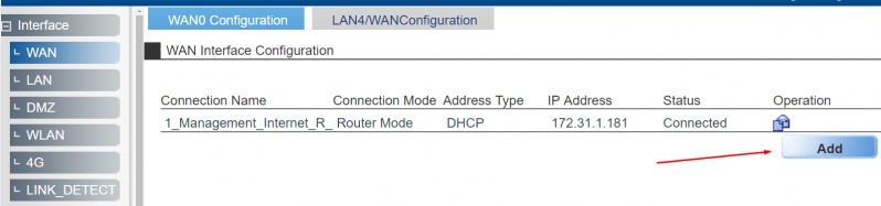
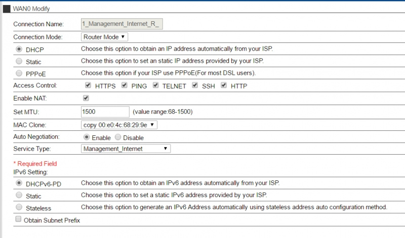
For an end user, setting up IPoE from the conditions looks quite simple: I plugged the optical connector into the transceiver or RJ45 into the copper WAN port, and Internet access appeared. For more precise configuration, consider the configuration of the WAN interface. Go to the menu Basic → Interface → WAN and click on the button to edit the interface as shown in the screenshot below:
In the menu that opens, various connection modes are available, DHCP / DHCPv6 / Static / Staticv6 / PPPoE (the router also supports L2TP, IPSec, PKI, GRE, EoIP - they are available in the VPN menu), access control functions to the router, NAT, MTU, MAC Clone Service Type (which can be applied to the Internet, SIP, IPTV). In our example, leave as shown in the screenshot below, and click OK:
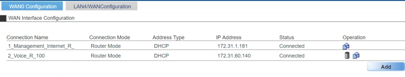
With this configuration, the router will automatically receive the network details that will be visible in the WAN interfaces:

If your operator uses L2TP connection, go to the VPN menu - L2TP - L2TP Client, and fill in the fields in accordance with your agreement:
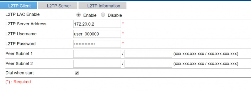
This is the minimum configuration required to connect. If the connection is successful, the status on the same tab for L2TP will change from DOWN to UP:

SIP interface
With the SIP interface, actions are similar to those described in the previous chapter. To create, go back to the Interface - WAN tab, and click Add to add a new interface:
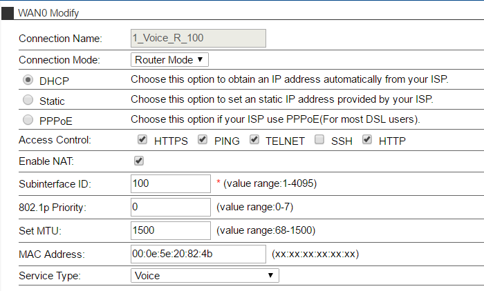
In the menu that appears, fill in the options as shown in the example below:
Put a dot on DHCP, specify the VLANID for SIP in Subinterface ID, if necessary put a tick in the option Enable NAT and click OK. If everything is done correctly, a new interface will appear in the list with interfaces, and will automatically receive network credentials via DHCP:
Setting up a SIP account
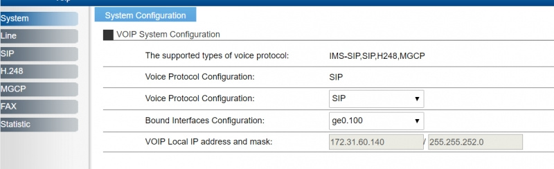
Go to the menu tab VoIP - System
Router \ Gateway supports multiple protocols - IMS-SIP, SIP, H.248 and MGCP. Therefore, from the drop-down list, you must select the one you need to work with VoIP.

In our example, we use Asterisk-based IP-PBX, so feel free to choose SIP. In the Bound Interfaces Configuration, you must select an interface (VLAN), from which you will be registered on the station. If done correctly, the final page should look like this:
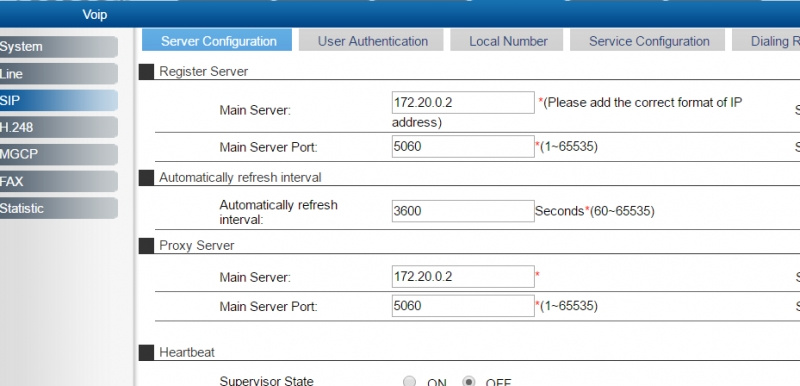
To configure the PBX server address information, go to the SIP - Server Configuration tab, specify the PBX server address and port (default is 5060), and click OK.
To configure credentials, go to the User Authentication tab and in the Operation column, click the icon to edit an account. It is necessary to fill it in accordance with the given details, and then click OK to apply the configuration.
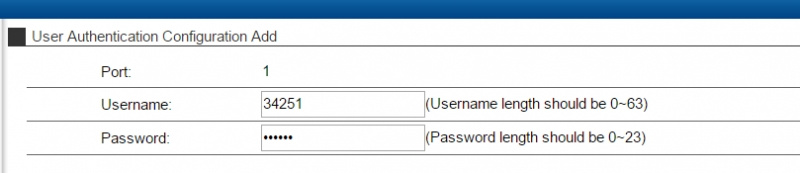
If everything is done correctly, the registration status will change to Successful, indicating a successful registration.

For more detailed configuration of lines on the System and SIP tabs, the Advanced Options menu is available.
Now, to check the connection, it is enough to connect an analog telephone to the FXS # 1 interface and make the first call.
By the way, an interesting point: it is not necessary to connect an analog telephone to the FXS interfaces. For example, if the office has an analog PBX and we need to connect an external SIP line to it, then we can easily stretch the cable from the gateway to the PBX and get the cherished one.
In this scheme, asterisk was used as a test environment, and therefore nothing prevents the use of services such as zadarma, mango, telfin, multi-phone and many others.
Configuring the interface to work with IPTV
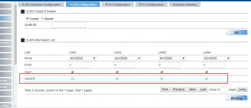
We return to the tab Basic - Interface - LAN - VLAN Configuration.
To create a VLAN, enter the required tag in the VLAN ID field. For example, for VoIP VLAN, enter 200, and click OK.
After application, the created VLAN appears in the VLAN Information List.
Now go to the WAN tab and click on Add to create a new interface. You can configure it like this:

vlan200 must be moved by double clicking on the right column.
Then you need to click OK to create a new interface. If done correctly, the list of interfaces should now look like this:

To select a port for STB, you need to go to Interface - LAN - Vlan configuration again, tick the vlan200 checkbox (IPTV Vlan) on the correct port and click Binding.

Now, if you connect the console to the LAN1 port, it should get the IP address from the VLAN 200 network and start working. With a different configuration (or with special need), you can enable IGMP mechanisms, the configuration of which is available on the Network - Multicast tab.
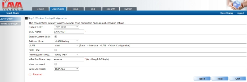
Wi-Fi setup
Wireless interface settings are in the Interface - WLAN menu. By default, up to 5 SSID connections are available on the router.

Which can be configured to work in different VLANs.
Select the desired SSID "LAVA-0001", click on the "edit" in the column Operation. In the menu that appears, you can change the name, vlan network, channels, isolation, and other parameters to fit your needs.

Click OK to apply the configuration, and then click Save Config to save it. If the configuration is not saved, then when the router is restarted, it will return to its original state.
USB 3G / 4G
Earlier it was mentioned that there is a USB interface onboard the router, which can be used to connect a 3G / 4G modem as a primary or backup link.
The menu for the modem configuration is located on the Basic - Interface - 4G tab.
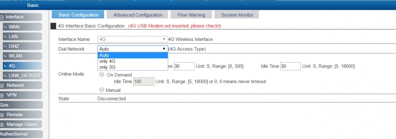
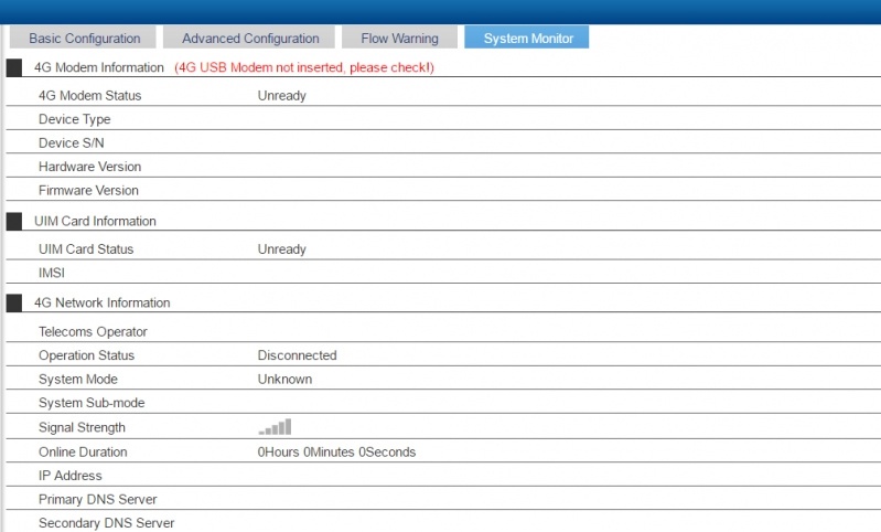
The menu contains the necessary tabs with options for operating 3G / 4G modems, and the System Monitor tab, if there is a connected modem, will show information about the device:
Reservation
The above-described 3G / 4G interface can be used as a spare, i.e. for the organization of a backup communication channel. For example, if you go to the Interface tab - Link_Detect, you can set the main link as the main link, the backup link and the 3G / 4G backup link, and specify the node that will be checked. Ie the logic is as follows: if the specified node does not respond, then switch to Backup Link.

QoS
Both at home and in a small company, QoS is a hot topic. There are different mechanisms on the router, but we’ll look at the restriction for user groups. For example, let's try to create a group “Company”, in which there will be two users, and for them every day during the whole working week there will be a speed limiting rule from 08:00 to 18:00, and then the restriction will be removed.
First, you need to create a group and add the necessary users to it.
Go to the Manage Users - Um tab, select the “Company” group already created by default and click Add under the table with users.

There is nothing to emphasize here, except:
Auth mode - in option available authentication by:
- ldap
- radius,
- ip,
- mac, which we will use.
Fill in the remaining fields as you see fit.
After users are created, you can go to the QoS menu and in the very first User Bandwidth Management tab add a new rule by clicking on Add:

Let's try the “Company” group to limit the speed to 4mbps daily. For this we are interested in the following options:
- Description: for_company (title \ description for the rule);
- Direction: bidirection (the direction in which the rule will operate in both directions);
- Rate: 4000 (speed in kbps);
- Way of Limit: Rate limit by user group (rate limit per user group);
- User group: company (select the group in which the necessary users are located);
- Start time-stop time: 08: 0 - 18:00 (time of the rule);
- Type of Limit: protocol ANY (the protocol for which you want to enable the restriction).

Thus, we create a rule called for_company, in which the download / upload limit will be up to 4000kbps. The restriction will apply to users who are in the Company group, and act every day except Sat-Sun from 08:00 to 18:00 for all types of connections. With regards to the temporary rule, you need to make sure that NTP is configured on the router and the time is correct. Otherwise, the created rule will not work correctly.
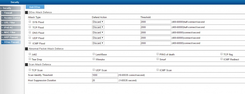
Security
Security should not be neglected, the LR-2G211 has internal mechanisms to protect its network.
The LR-2G211 is a fully functional router not only for a home user, but also for a small office network.
Do you need optics, Wi-Fi, SIP-gateway, IP-TV in one piece of hardware in the office or at home? Then you definitely should pay attention to the LR-2G211 !
Price at the time of publication:

All Articles