Another smart watch do it yourself
Being inspired some time ago with the article “Smart watches with your own hands for 1500 rubles.” , I also decided to try to make a similar device.
This article is not positioned as a guide to action or instruction, rather as an indication of the key points that I had to face. Perhaps, it will serve someone as a source of inspiration and useful information.
Selection of components, wiring board, soldering in harsh conditions, 3D-printed case and JavaScript on the clock - under the cut. Welcome!
Requirements
- Need to know the time without having to reach into your pocket for your phone.
- There should be a reception of notifications about incoming calls, SMS and notifications from instant messengers
- Battery life must be at least a week.
- Be as compact as possible
Already on the basis of this small list of requirements, you can proceed to the selection of components and refinement of the technical features of the implementation. The project budget for time and finance was not particularly limited, mass production was not planned, so you could afford to roam and not much to bathe over the savings of every penny.
In addition to general-purpose women, there were also purely technical ones:
- Create and run custom applications on the clock. Like a pebble . In general, here and further, the clock will increasingly resemble a Pebble clone, but why not
- Memory for applications and their data
- Adequate control of the charge level so that the watch is not cut down suddenly when the battery is discharged, but showed "sticks" and warned in advance
- Accelerometer, gyroscope and magnetometer for full user tracking. To be able to make a pedometer or a smart alarm clock that monitors the phases of sleep by the presence of movement
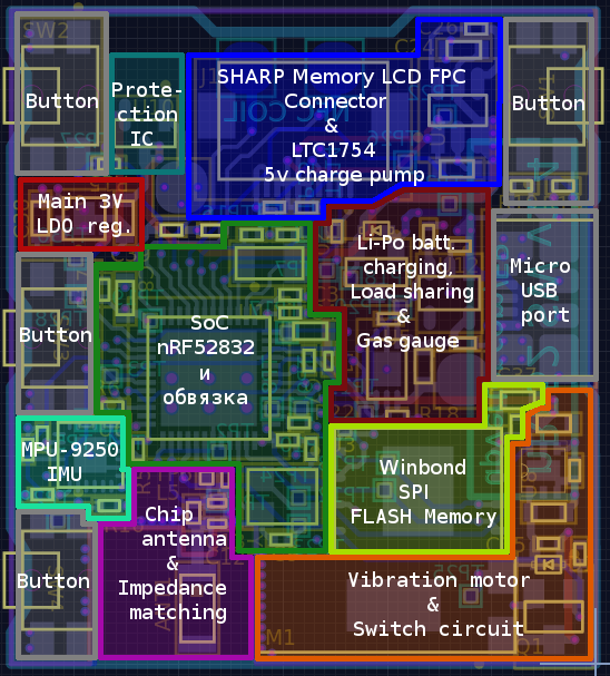
All this eventually crystallized into a small diagram:
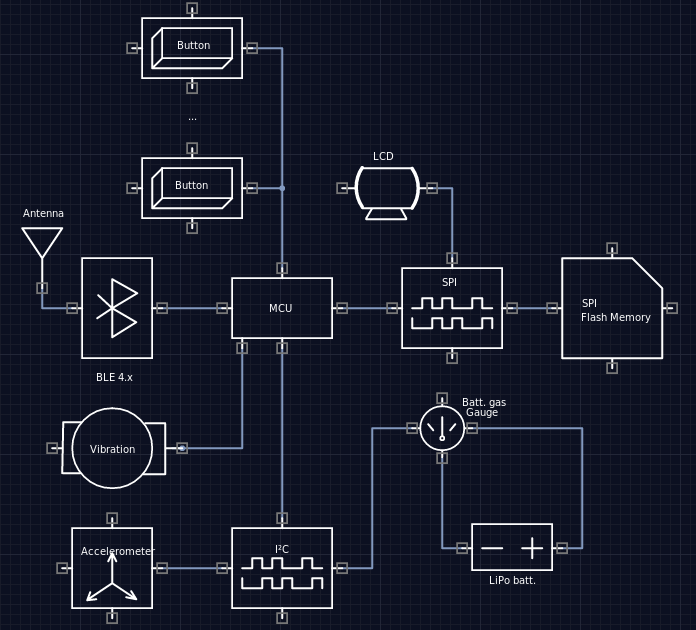
The microcontroller combines BLE 4.x for communication with a smartphone, I²C and SPI buses for sensors and a display with memory, controls vibration and responds to button presses, everything is powered by a Li-Po battery.
Now you can begin the process of selecting chips and parts. By laboriousness and time spent, it was the most difficult and lengthy process, it was necessary to compare a lot of things, look for, and dive headlong into places where I hadn’t been swimming before.
Component selection
Microcontroller
The first thing you need to choose a controller that will be the "brain" of the device and everything else on the board will serve him for good.
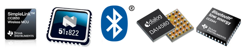
To make the device more compact, you need to use as few components and modules as possible. Here come to the aid various systems on a chip that combine the functionality of a bluetooth module and a microcontroller.
Source: www.argenox.com
- Cypress PSoC BLE core ARM Cortex-M0, BLE 4.2, 256kB FLASH, 32kB RAM, a bunch of peripherals and a built-in balun , wide supply voltage range: 1.9-5 volts
- Texas Insturments CC2541 - BLE 4.0 and 8051-core, 256kB FLASH, 8kB RAM
- Texas Instruments CC2640 - BLE 4.1, Cortex-M3, 128kB Flash, 20kB RAM
- Dialog DA-14580 - Cortex-M0, BLE 4.1, 16 MHz, 42 + 8kB RAM, 32kB OTP (once programmable memory, but it is possible to run code from external SPI FLASH), the smallest and least consuming chip of the listed
- SiLabs EFR32 - Cortex-M4F, 40 MHz, BLE 4.x, Bluetooth 5, up to 1MB FLASH, up to 256kB RAM
- Nordic nRF52832 - Cortex-M4F, 64MHz, BLE 4.x, Bluetooth 5, 512kB FLASH, 64kB RAM, NFC tag emulation, balun built-in
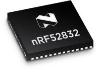
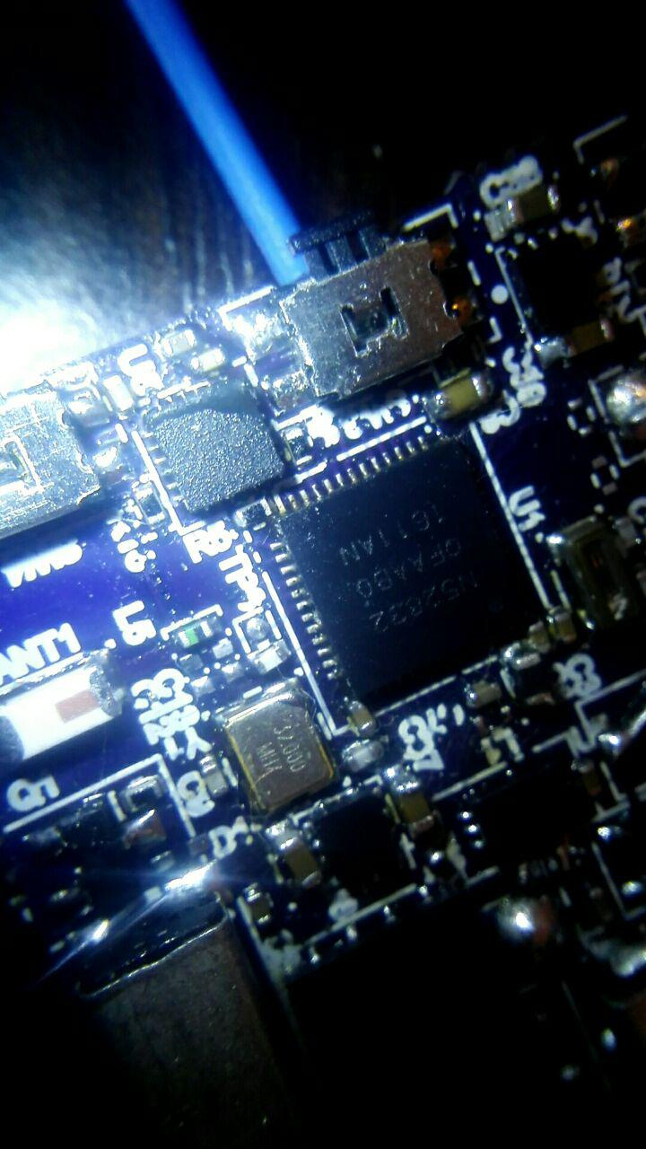
In a heap of tasty and not very solutions, the choice fell on the nRF52832 , this chip turned out to be the most productive and quite convenient in terms of the case (6x6mm 48-pin QFN). Also a smart option, greatly simplifying the layout of the board, is the ability to programmatically assign any peripherals to any of the GPIO outputs. This is what so many microcontrollers lack. Thanks to NFC support, you can add NFC-emulator functionality to your watch and sew up all your security cards with it.
The datasheet says that there is a built-in RTC (real time clock), this is convenient. But later it turned out that this is not a clock, but a Real-Time Counter , i.e. This is the most common timer, working on 32.768kHz quartz, including in sleep mode. Therefore, in the next revision of the device I will use a separate chip for the RTC, for example STMicroelectronics M41T62LC6F . It has a built-in quartz at 32.768kHz and works on the I²C interface.
The debug nRF52-DK is pretty cheap , about 4 thousand. rubles. On Aliexpress you can find for ~ 3 thousand.
Since the device does not imply mass production and any market sale, then drawing your board and building your solution on the BLE SoC is quite an exciting lesson without serious consequences. For those who want to quickly enter the market, it is recommended to use ready-made pre-certified modules .
There are several reasons for this and they are related to radio: for any new electronic device on the market, it is necessary to obtain a permit and be certified by such regulators as CE and FCC .

Concomitant pleasures include special layout of the board taking into account the features of signal propagation with a frequency of 2.4 GHz, shielding, measurements in an anechoic chamber, impedance matching and other microwave magic. In the ready-made modules, all this work has already been done by their developers, it’s enough for the user to embed the module in his decision and certify nothing anymore.
Quartz resonators
Quartz resonators are connected to the selected nRF52832 chip:
- At 32MHz for core and radio clocking, mandatory
- At 32.768kHz for clocking the clock timer and BLE time slots during sleep mode. It is optional, but connecting it reduces power consumption (time slots can be made shorter) and increases the accuracy of the RTC hour timer.
Both types of quartz are ordered in a surface mount housing from Aliexpress:
Display
To watch ticking without recharging at least a week away, you need to solve the problem that the display matrix in the operating mode consumes a lot of current. As I understand it, watch manufacturers solve this problem in two ways:
- Turn on the display and display the contents only when a wave of the hand occurs and the clock screen gets into the user's field of view, or when the user's attention has already been attracted, for example, by a notification or an alarm clock
- Display content continuously using displays that practically do not consume current to display a picture, but consume it only to update the content. There is no need to go far for examples: this is e-ink , Memory LCD or IMOD / mirasol
For the variant when the display is Malevich’s work most of the time, there are such options on the market: OLED, TFT, Amoled, LCD telephone modules (Nokia, Siemens, etc.). It remains to find a display with a suitable diagonal.
Examples:
- Small OLED displays , on Ali Express such cost a penny.
Cons of a bunch: a small diagonal, monochrome, consumption of 10-20mA, bulky module. Without a module board, there is a wide trail and a sea of strapping that will absorb a significant piece of area on the board. - TFT LCD, for example ILI9341 . Of the minuses: consumption, wide plume
The screens on the E-Ink disappeared immediately, because the screen refresh rate is too slow, monochrome and, most likely, it is difficult to find a fairly small E-Ink display on the open market.
If you look at Pebble , you can see that it uses the “Always on” display. Pebble Classic uses a monochrome SHARP Memory LCD display, Pebble Time uses a color (64 color) display using a similar technology, but produced by JDI , it is not available for sale in the open market.
Regarding IMOD / Mirasol, nothing was found except marketing brochures and Toq watches from Qualcomm .
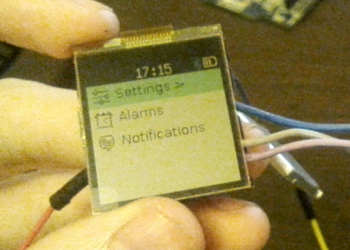
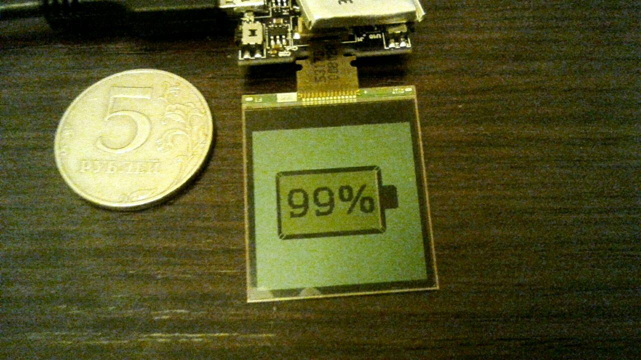
I wanted to take a color display like Pebble Time. The closest analogue, which is in the open sale, was the SHARP LS013B7DH06 ( its datasheet ).
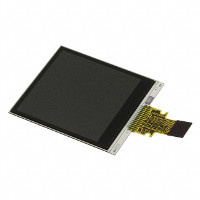
Specifications:
- 1.33 "diagonal
- Resolution: 128x128, 8 colors (3 bits per pixel)
- Dimensions: 26.82x31.3mm
- Interface: SPI
- Power supply: 5V, but SPI logic levels from 2.7V
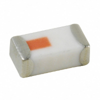
The supply voltage turned out to be an ambush, because the Li-Po battery does not get the required 5V voltage without additional step-up converters. But the current at the display is scanty and getting the necessary 5V is quite simple using a charge pump of the type Linear LTC1754-5 :
Another feature was the need to switch the status of the EXTCOMIN pin (External COM Inversion) from high to low and vice versa, so that the charge did not accumulate on the screen panel and the picture did not freeze at one point. For these purposes, you can dispose of the built-in PWM (PWM) microcontroller, tuned to a duty cycle of 50% (square wave) and at a frequency of 1 Hz or higher, or any other (including external) square wave generator.
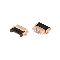
The display connects to the board using a small cable, it is very convenient to use a FPC connector with 10 pins in 0.5mm increments, for example Hirose FH12-10S-0.5SH :
The display module does not have its own backlight and doesn’t show through the LEDs through like a normal LCD screen, so for the time being, we don’t have to watch the clock without the backlight at night. If someone is familiar with the process of creating a backlight module for this kind of screens, please respond.
Battery
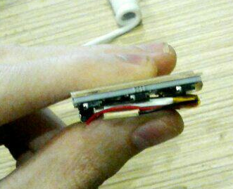
I had to spend some time trying to choose a suitable size battery from the standard nomenclature of sizes. I was looking for a lithium-polymer battery with a voltage of 3.7V and with a capacity of approximately 100mAh.
The battery was planned to be placed under the board, knowing the size of the board, you can easily pick up a battery that will fit and nothing will stick out.
On Aliexpress, you can order a whole lot of batteries for almost any size, the main thing is to know the coding system of their names. And it’s like this: HHWWLL, where HH is the thickness (height) of the battery in tenths of a millimeter, WW is its width and LL is its length in millimeters.
Example: 402025 - battery with a thickness of 4mm and dimensions of 20x25mm
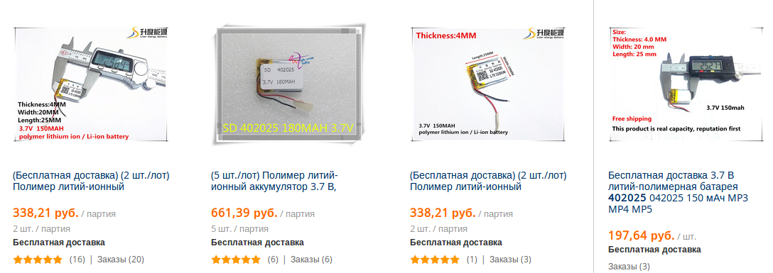
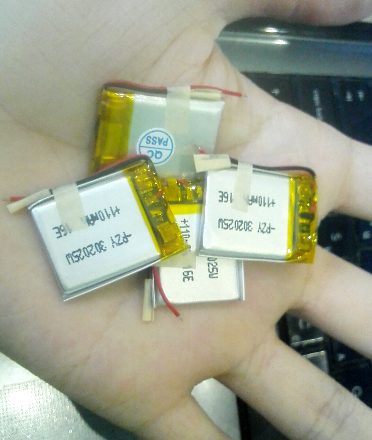
Were selected batteries 302025 (3x20x25mm) 110mAh capacity and ordered on Aliexpress.
Nutrition
Since it makes sense to discharge lithium-polymer batteries only up to 3 volts, it was decided to power the entire circuit from stabilized 3V and if the battery voltage dropped below 3V, then cut off the main power regulator with a protection chip ( Maxim MAX809TEUR + T ).
The total supply voltage of 3V fits into the power ranges of all circuit elements, except for the display, which needs 5V. Therefore, the display is powered via a Linear LTC1754-5 boost converter directly from the battery.
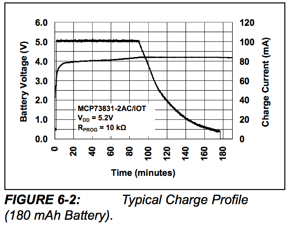
If you look at the discharge curve of this type of battery,
it can be seen that the entire battery capacity falls on the voltage range from ~ 4V to 3V, so a conventional 3V down converter will be enough to provide the system with a stable voltage and efficiently suck all the energy out of the battery, leaving nothing, but not re-discharging it .
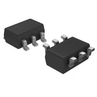
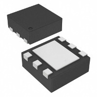
Texas Instruments TPS78230DRVT was chosen as a down converter; it has a small operating current of 500nA and a maximum current of 150mA, which is quite enough. The case of SON-6 is compact and quite easy-to-work:
Accumulator charging
It was decided to charge the battery through a standard microUSB port ( Molex 47346-0001 ), but it is not enough to simply connect the battery directly to the 5V bus from USB and charge it, you need to ensure the correct charging process, divided into several phases: preconditioning, constant current, constant voltage.
A popular solution for charging small-capacity batteries (up to 500mAh) is the Microchip MCP73831 chip . Charging current (depending on battery capacity) is programmed with a resistor, there is a tri-state or open-drain output for notification of the beginning and end of the charging process.
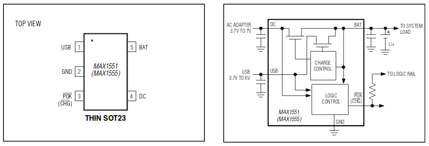
I also chose another chip - Maxim MAX1555EZK-T . It has a fixed charging current of 100mAh and has the same case as the microchip from Microchip and at the same time requires a minimum of external components and has an open-drain output to alert about the charging process:
In the next revision of the board, I will switch to a microchip from Microchip, because the charging current of 100mA for a 110mAh battery is probably a bit too much.
Battery Capacity Controller
There are several different in terms of performance and accuracy of the final result of techniques for tracking the state of charge of the battery (in English sources this is called the State of Charge):
Measure the so-called. open circuit voltage / OCV (voltage on the plates) of the battery through the ADC and make a conclusion about the battery capacity. Most often, it is necessary to transfer the voltage range to an area that is acceptable for the operation of the ADC using a voltage divider. The disadvantages of this approach are that the graph of the dependence of voltage on the capacity of lithium-polymer batteries is rather flat, and the readings themselves change with each cycle and are subject to noise and the fundamental inability to measure the actual voltage on the plates due to the influence of the load current
Another way is instead of measuring the voltage on the plates to measure the current that flows into and out of the battery. This is called coulomb counting. A typical solution is to integrate the value of the voltage drop across a shunt resistor of small resistance (about 100mOhm). Knowing the capacity of the battery, the current that has flowed out of it for a certain period of time, we can conclude how much more energy is left in the battery (neglecting the self-discharge). The disadvantages of this approach are that self-discharge is not taken into account, as well as the fact that the true battery capacity changes with each charge-discharge cycle. Roughly speaking, less current flows from a battery than it flows into it when charging. Because of this, over time, an error in the readings will inevitably accumulate
- Combining the first and second methods: measuring the voltage on the plates and the flowing current. Proper combination of two approaches will help build a model that will evaluate battery capacity with good accuracy. In order for this approach to work, it is necessary to perform at least one charge-discharge cycle to collect data on the dependence of the voltage on the plates against the capacitance. And each next cycle will have to make changes to the battery model so that the error does not accumulate. There are articles in which people tell how using the Kalman filter combined data from different measurements to predict the remaining charge ( [1] , [2] )
- Maxim MAX17043 - using a proprietary algorithm for the voltage on the plates builds a battery model inside. Promises accuracy of measurement of the remaining charge in 3%. Interface I²C. Nice and small body
- OnSemi LC709203F - measures OCV, I²C interface, 2.8% accuracy, there is temperature compensation through an external thermistor. Expensive and bad in Russia
- Texas Instruments BQ27621 - measures the voltage on the plates, I²C, accuracy is not specified, is expensive, BGA package
- Texas Instruments BQ27421 - measures voltage and current at the same time. I²C interface, accuracy not specified, costly, BGA package
- Linear LTC2941 - measures the flowing current, I²C interface, accuracy 1%, additionally requires an external shunt resistor (in LTC2941-1 it is built-in), housing: 2x3mm DFN-6
Of the available options was selected chip Linear LTC2941 for the smallest, but the casing and intelligible algorithm work. Ordered by Aliexpress.

Source: Linear Technology
The microcircuit uses the coulomb counter technique and considers the flowing current with an accuracy of 1%, works on the I²C (SMBus) interface and has a small but comfortable case: 2x3mm DFN-6:

Through I²C inside the chip, you can set the value of the current counter current divider, as well as set or read the value of the meter itself. The counter is 16-bit and increases when the current flows into the battery and decreases when the current flows from the battery. The maximum value of the counter (0xFFFF) can be taken as a fully charged battery, and the minimum (0x0000) as a fully discharged one. With a well-chosen counter predecessor, you can ensure that the meter reaches the maximum during charging, and reaches zero when the battery is completely discharged. It is possible to set the limit of the counter value, below which the microcircuit will sound the alarm and issue an interrupt.
Accelerometer
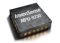
A rather popular chip was chosen among the heaps of options on the market: the InvenSense MPU-9250 . This is a system in the body (SiP), combining MEMS Acceleromer, MEMS gyroscope and magnetometer chip.
- Power supply from 2.4V to 3.6V
- 16-bit three-axis MEMS accelerometer with measuring ranges ± 2g, ± 4g, ± 8g, ± 16g
- 16-bit three-axis MEMS gyro up to 2000 ° / sec
- 16-bit three-axis magnetometer with a measurement range of up to ± 4800μT
- Built-in digital filters
- Interfaces I²C and SPI
- Programmable interrupts
- Coprocessor for processing DMP (Digital Motion Processor) readings
The chip is excellent, but in the end it seemed to be overkill and a simple accelerometer is enough for use in the clock. For example, Analog ADXL362 - according to the manufacturer, this is the most economical three-axis MEMS accelerometer.
Flash memory
It was decided to use external SPI-FLASH memory for applications and data. The Winbond W25Q256FV chip in the compact WSON-8 package was chosen from a variety of options:
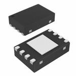
The amount of flash memory is 256 megabytes (or 32 megabytes), quite enough. The memory is divided into pages of 256 bytes, grouped into sectors of 4 kilobytes and blocks of 32 kilobytes. In the active mode (read or write) it consumes up to 20mA, in the standby mode - less than 1μA.
As with the accelerometer, later it began to seem that 32 megabytes is also an overkill and you could instead use the built-in FLASH memory of the microcontroller, it already has 512 kilobytes. But the place on the board was and the desire to have the file system right on the clock was also present.
Buttons
I wanted to control the interface by pressing the buttons on the side of the case (just like Pebble, what a coincidence). I could not find a touchscreen for such a small screen diagonal. He didn’t strongly bother himself with the choice of buttons and chose the first ones that were at right angles to the board and that were caught by the arm:
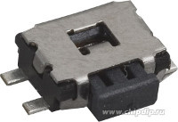
Source: Chip & Dip
Then it turned out that the plastic in the buttons rather poorly tolerates soldering with a hair dryer and washing the board with acetone.
Alternatively, I found buttons from Omron B3U-3000P :
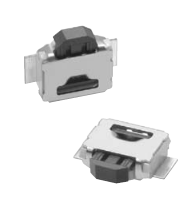
I will use them in the next board revision.
Vibration motor
To notify events such as alerts or an alarm clock, you need a vibration.
A handful of SMDs for surface mounting working from 3V and dimensions (HxWxL) 3x3x12mm were ordered on Aliexpress:
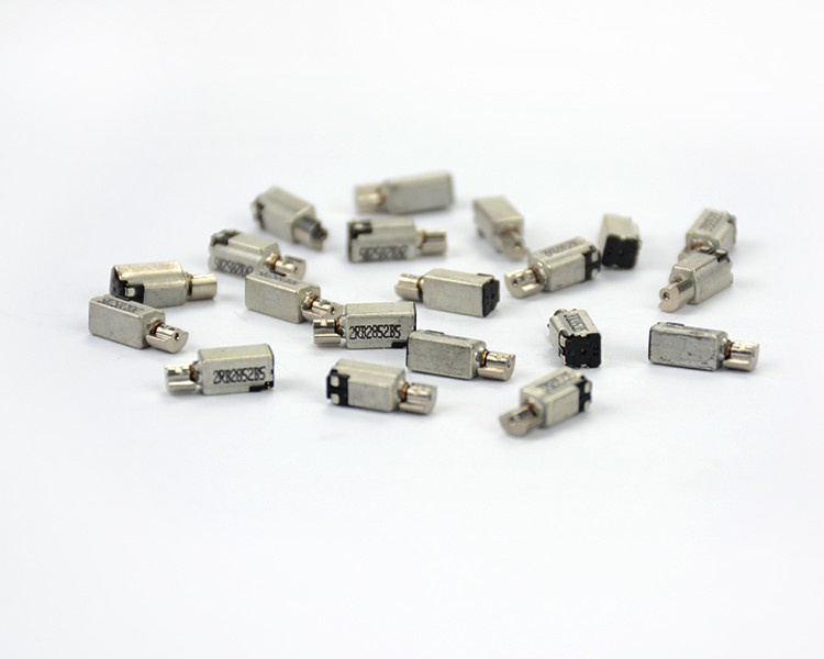
The motor is well soldered to the board with a solder paste, consumes 100mA at the peak and gives a good and tangible vibration.
Antenna
Due to limitations on the available board area, a surface-mounted chip antenna was chosen as the antenna. These are ceramic parts inside which a conductor acting as an antenna is wound in a special way. The gain of these antennas is miserable, but this is enough for a wearable device paired with a smartphone. During the tests, it turned out that the two concrete walls in the apartment also punched the signal completely.
The first chip antenna on 2.4GHz was Johanson 2450AT18B100 :
In general, these are quite popular antennas, and Johanson themselves produce more baloons, specially optimized for certain manufacturers, including for Nordic. Johanson 2450FM07A0029 harmonic filter was made specially for nRF52 Johanson, which replaces the LC filter in front of the antenna recommended in the reference design.
Antennas were ordered on aliexpress tape for 10pcs. for 214r / tape.
All the rest
The passive components for braces and strapping are mainly chip sizes 0402 and 0603 and are ordered from Elitan . In addition to the passive components, there are two transistors and a pair of diodes on the board. They participate in the control of the vibration motor, as well as in the power circuit, decoupling the power from USB and battery .
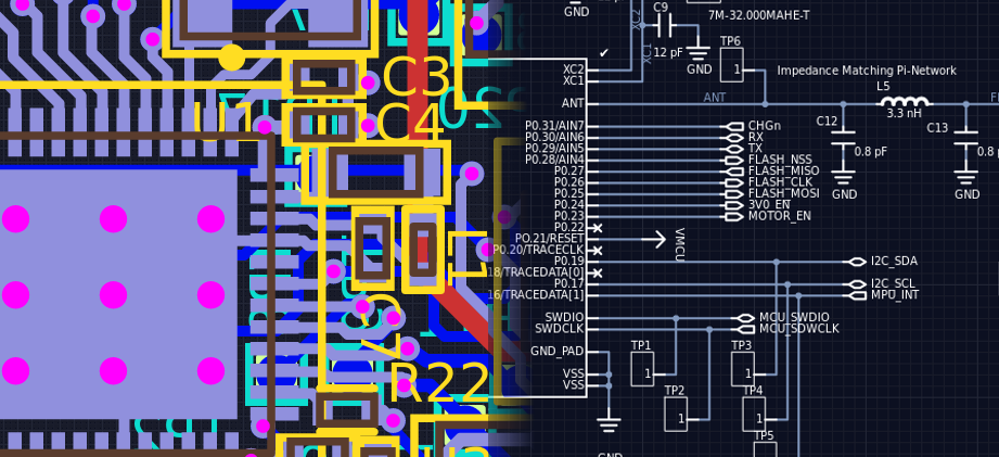
Scheme and fee
The appearance of the board in the screenshots is slightly different from what was ordered and is present in the photos of the device. In the screenshots of the board just a little later revision with minor changes.
Having decided to try something new, I drew a scheme and board not in the usual DipTrace, but in the cloudy EDA Upverter: a link to the design .
Upverter allows for the end-to-end design of the board and the circuit at the same time, so part of the layout elements was carried out according to the scheme, and part of the scheme was designed taking into account the layout features.
Another killer feature of Upverter is a huge library of components, carefully generated by bots and a bunch of Indians. , - , , .
, : , microUSB . , , .
, «rule of thumb» . - keepout-, , , . , . ( ), , .
( ) . , nRF52 .
, 90% , .

:
, , , , .
, OSHPark.com :
- /: 5/5 Mil
- : 10/4 Mil /
- : FR408
- : (ENIG)
- (blind vias) (buried vias) .
$10 . — 3. ( ) , , .
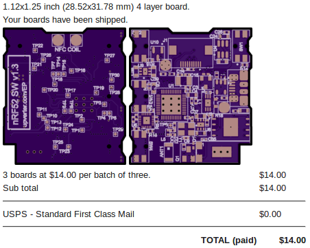
$14 .

, , NFC, .
test-point-, , I²C, SPI, . . JTAG (SWD) Segger JLink, nRF52-DK, NFC-.
, smd- (smd stencil) , , (reflow oven) .
, . . . , 0402, , .
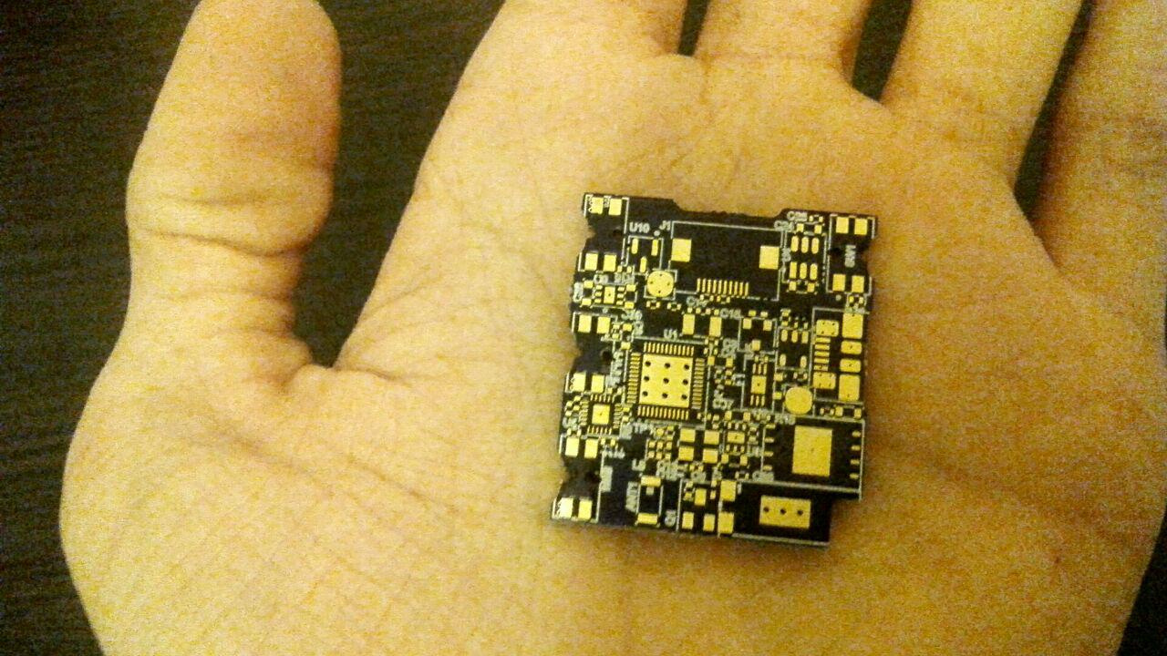
:
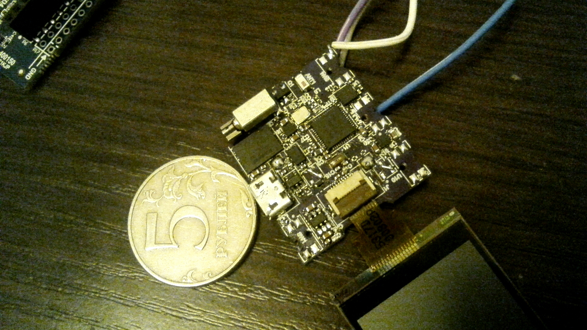
, — .
, .
. .
, , , . , , , USB-. , , USB- — 5 , — 4.2V, LDO — . It seems to work.
, , , . — ( « », : WatchOS, PebbleOS, etc.).
JLink, nRF52-DK SWD. , JLinkExe ! .
« »
, Nordic nRF5-SDK , nRF51 nRF52 .

SDK , , NFC . Makefile arm-none-eabi-gcc
. , .
.hex-, nRF52-DK . nRF52-DK , Mass Storage Device (), .hex .
JLinkExe
GDB- nrfjprog
.
, . , , , , .
, .
, -, , .
, , - . API X-Lib . , .
:


, API , JavaScript (ES 5), . , .
JerryScript, , API , , . , , : Date .., JSON-, ..
JS :
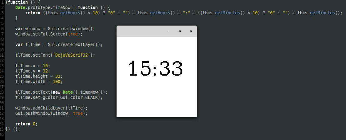
API GUI, , Bluetooth, ..
( -O0
):

106kB FLASH, 12.8kB RAM. 8kB RAM — (heap) JavaScript . . , FLASH nRF52832 512kB, RAM — 64kB.
FLASH (120kB) RAM BLE- SoftDevice.
— 3D- . TinkerCad 3D-. :
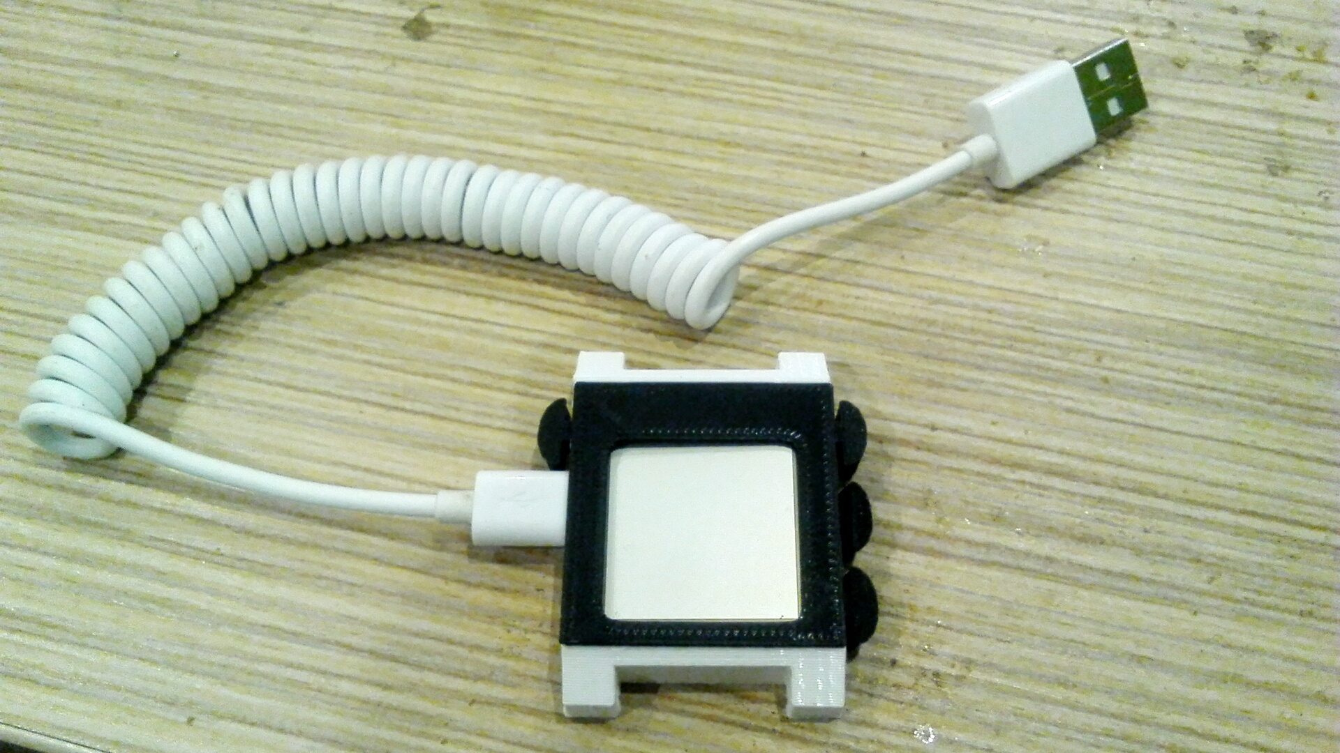
- 3D-, !
, . , , , . , , , .
, API- JS-, JS-, - Android. , . , , , Android- .
: https://upverter.com/EP/cdbd8b9abc72b7cd/nRF52-smart-watch/
, Github.
, , - , .
!
P.S.: .
All Articles