SportIduino - e-elevation system for Arduino for orienteering

Getting to nature is always great, but with a map in hand and with a conscious goal it is always more interesting. There are such types of outdoor activities as orienteering, rogaines, multi-races, participating in which you can have a good time. The task of the orienteer is to visit the control points marked on the map in the shortest time possible. In order to prove the fact of their visit, they are used as a so-called. “Traditional” marking systems: colored pencils, code symbols, composters, etc., as well as electronic systems. Despite the convenience of the latter, traditional methods are still widely used in amateur competitions. This is due to the cost of equipment (from 3500 rubles for the station mark and from 450 rubles for one chip), with the possibility of theft of stations installed in public places, the need to take a deposit for the chip. Therefore, I set a goal to create a more affordable alternative. The following describes its implementation in the Arduino environment.
The electronic tagging system usually consists of RFID chips and stations - special devices for their writing and reading. The system works as follows. At the start the athlete gets a chip, takes a card and starts. Running up to the gearbox, he puts his chip to the station mark, it records the current time on the chip and gives a signal, after which the athlete can continue on his way. At the finish, the athlete hands over the chip to the judge, who reads the information using the gateway and reads out the result to the athlete - his time at a distance, the number of visited kn, the compliance with a given direction. He can also print splits - time intervals spent on the path between the controls, which allows the athlete to analyze his way and compare himself with others on one or another segment of the distance.
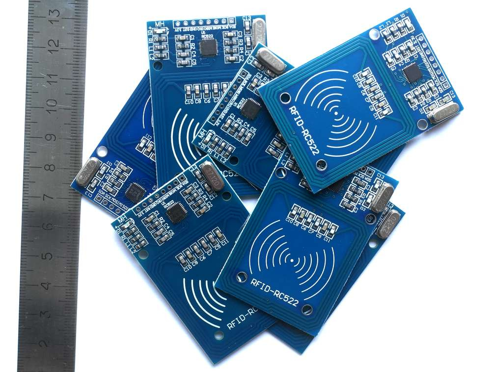
To work with RFID chips, there is a widely available module RFID-RC522, for which there is an excellent library for Arduino, in many respects this fact determined its use. The module operates at a frequency of 13.56 MHz and supports the ISO 14443 standard, works with various chips, reading and writing occurs from a distance of several centimeters, which is well suited for our purposes.
Chips
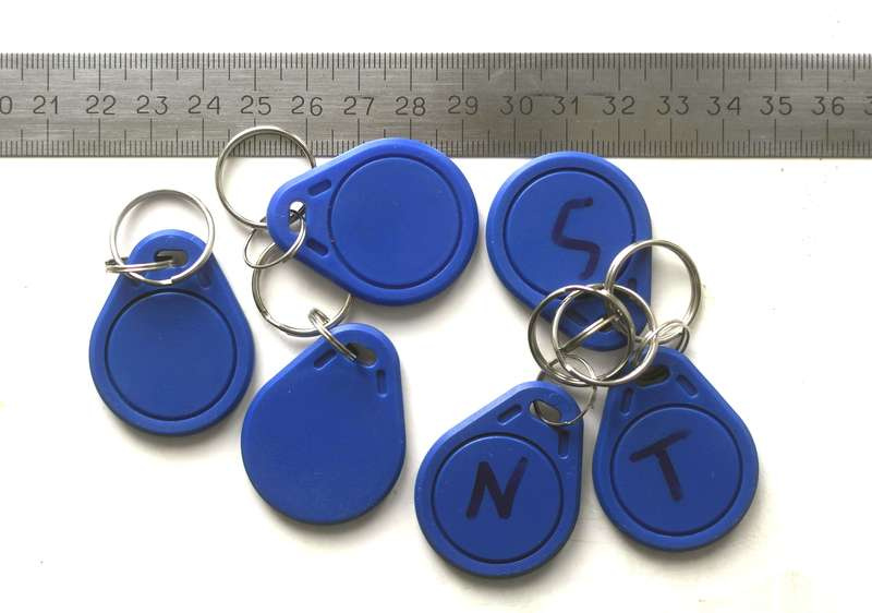
To create a marking system, I used the Mifare Classic 1K (S50) chip because of its wide availability in various versions and low cost (11 rubles per chip in the form of a keychain). The chip allows you to read and write information quickly and reliably. Chip memory is structurally divided into 16 sectors, each of which contains 4 blocks of 16 bytes. The 4th block of each sector contains the keys with the help of which it is possible to write / read blocks in the sector. In addition, in the zero sector, the zero block contains the UID and information about the manufacturer. Thus, 3 blocks of 16 bytes in sectors 1 through 15 and two blocks in the 0th sector remain for recording. The structure of the record is presented below in the table, all data is recorded in triplicate for reliability.
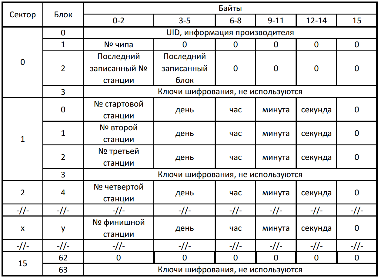
This recording system allows you to record 45 marks in memory, including start and finish, for most competitions this is quite enough. But if you optimize memory usage and put a little more time on the mark, the capacity can be significantly increased.
Stations of the mark
Scheme and installation
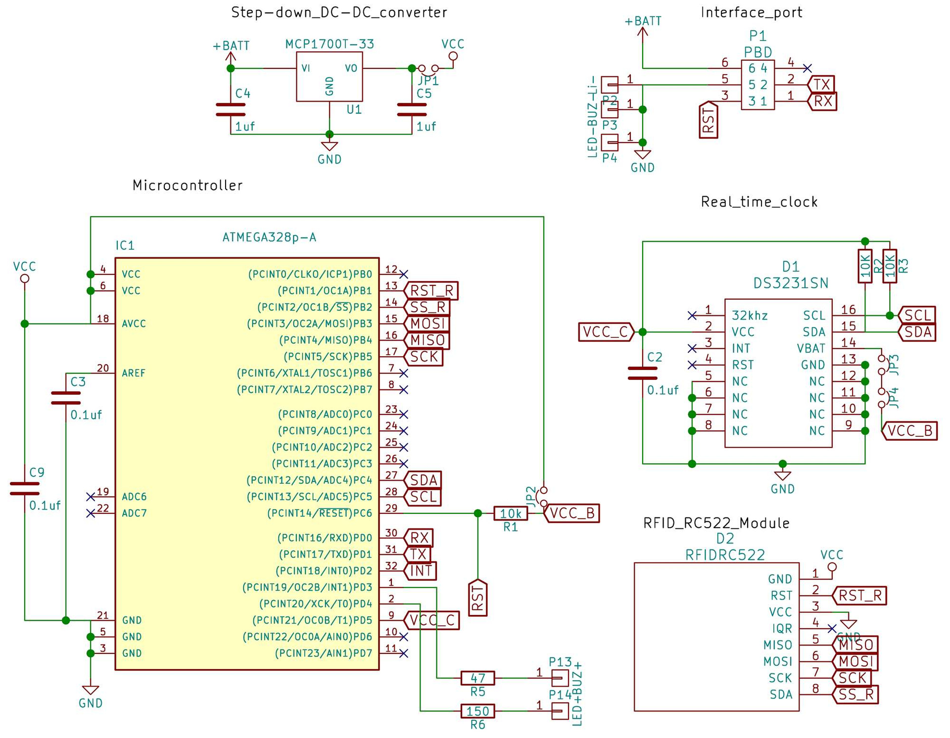
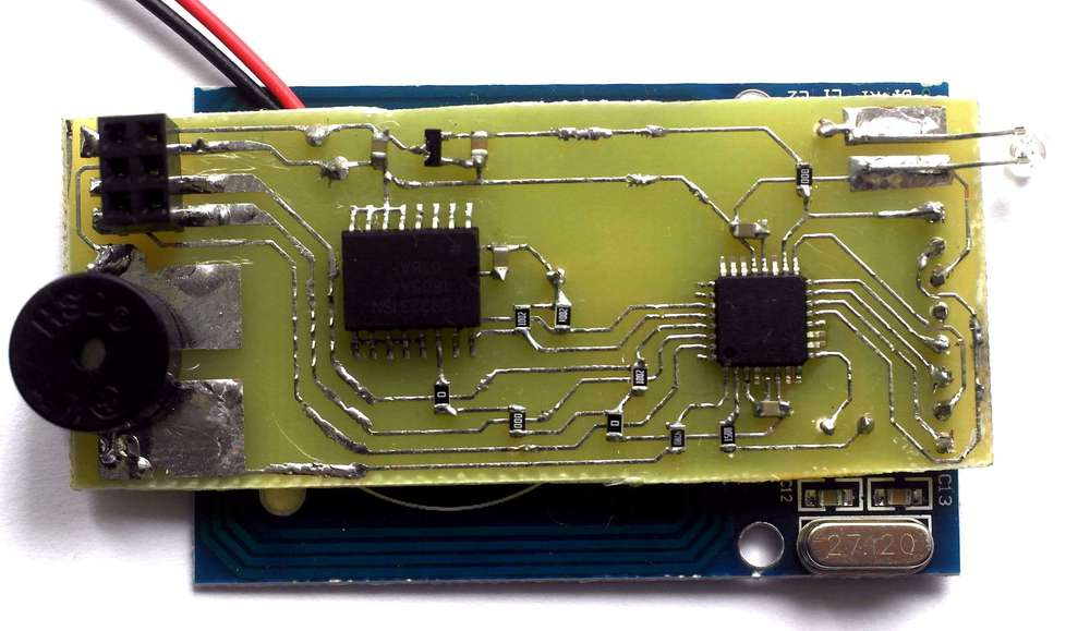
The main components of the station mark: the microcontroller - Atmega328p-au, RFID-module RC522, clock DS3231. Powered by 3 AA batteries through the MCP1700T-33 linear stabilizer.
I assembled the components on the printed circuit board, all the components of the SMD, with the RFID circuit board, made the soldering through the male connector. The boards were made using photoresist, 0.5 mm tracks. While honing the method has done quite a lot of defects, it is probably more expedient to make gerber files and order their production on the side, since this is not very expensive.
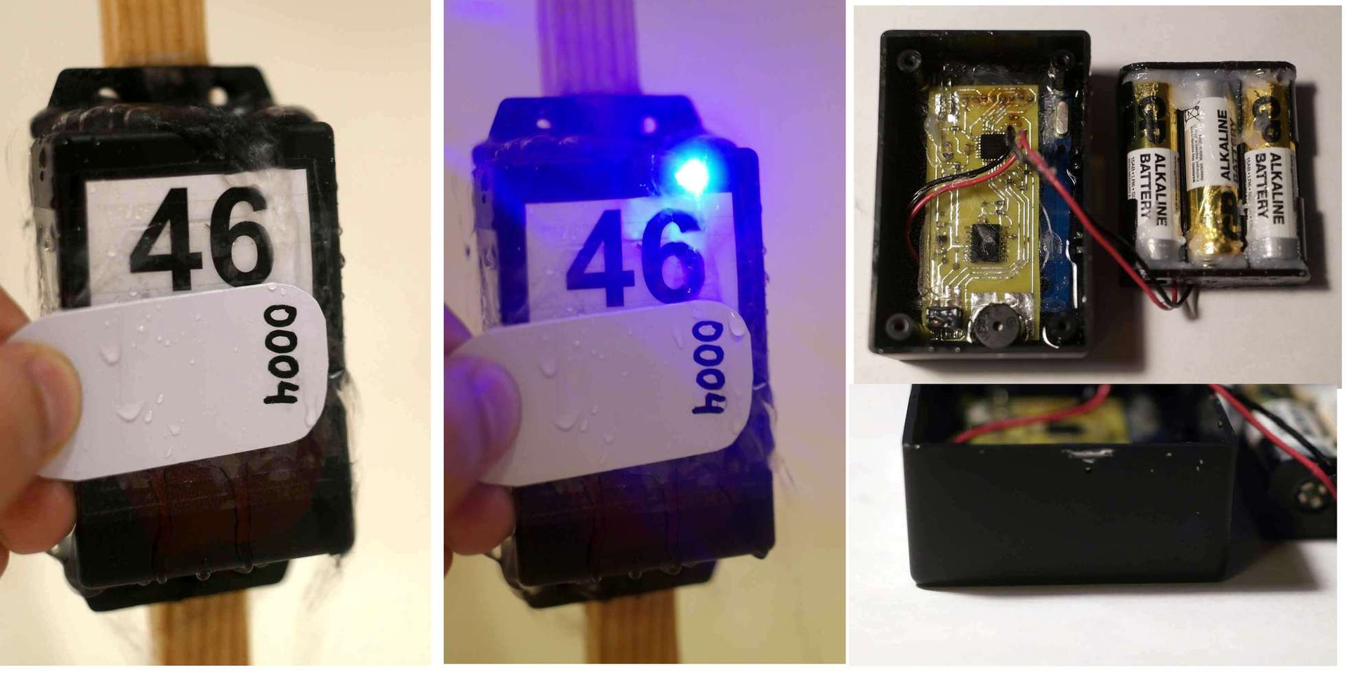
I use the available g1020BF as a case. In the box for the LED, drilled a hole and cut off excess plastic to fit the battery compartment. Hole for the LED epoxy treated, then insert the welded board. After curing epoxy, poured 30 milliliters of the compound PC-68, this was just enough to cover the board. In the battery compartment inserted batteries and all greased with grease for waterproofing. After tightening the lid the station is ready for use.
The cost of the station components and materials for its manufacture is about 500 rubles. It takes me about 1.5 hours of pure time to make and set up one station.
Station firmware
During the operation of the station, various kinds of failures are possible, it was necessary to implement the watchdog operation, so you need to use a compatible Bootloader in order for it to work correctly. A good version of the bootloader for Atmega328p and instructions for installing it are here . You should also change the standard library wire to non-blocking, so that the station continues to work when the i2c line breaks, and does not go into an infinite loop. I downloaded the bootloader using another Arduino via the Arduino as isp firmware, connected the SPI contacts via pins leading to the RFID module, which I took off after a successful download. Then installed the main firmware.
With the main firmware, the station with a chip tray reads a block of information from which it learns the numbers of the last recorded block and the station at which the mark occurred. If the station number is different, then the information block is updated and the station number and the current time are recorded in the next free block. Time and station number can be adjusted using special chips and gateways.
Nutrition
One of the most important issues that had to be solved was how to maximize the service life of stations from a set of batteries. This is especially critical for tourist orientation, when it happens that the stations are installed long before the competition and it is necessary that they function guaranteed for more than a month.
To reduce consumption, sleep modes are used for the controller, as well as for the RC522. In sleep mode, the station consumes only 0.02 mA versus 20 mA during operation. In order to more economically use energy, three modes of station operation have been implemented with different time intervals of sleep.
By default, the station starts in standby mode. At the same time, the search for a chip occurs once a second, the battery capacity lasts for 160 days. When a chip tray (this is done by the production director or the first athlete running to the station), the station goes into operation. In the operating mode, a chip search is implemented every 250 ms. New batteries will last for 45 days of continuous work. After 6 hours of inactivity, the station returns to idle mode.
When a sleep master chip is brought in (a special judge chip with station settings), the station goes into storage mode (chip search every 25 seconds), picks up 3 times and reboots. New batteries in this mode will be enough for 5 years. With a tray of any chip station goes into standby mode, while there is a measurement of the remaining battery charge. If the voltage drops below 3.1V, which indicates that about 15% of the charge remains, the station signals this.
Gateway and Data Processing
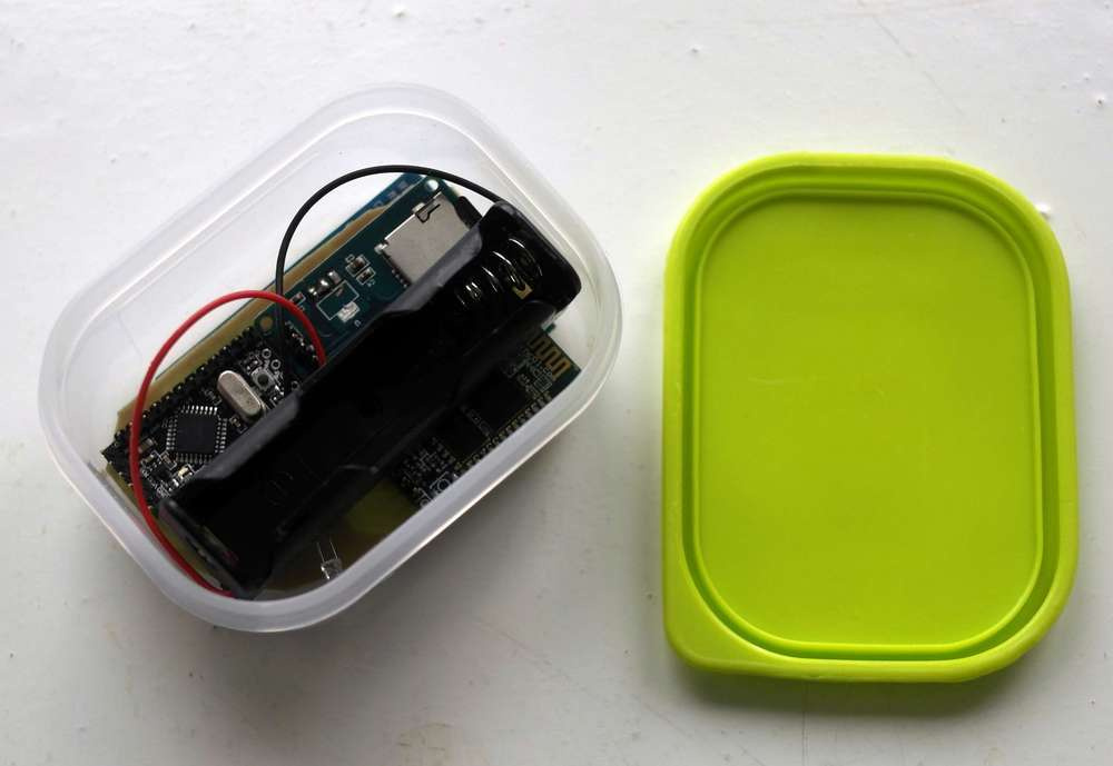
A gateway is provided for working with chips and mark stations. Using the gateway station, you can set and adjust the time and station numbers using special master chips. Also, the gateway station performs pre-launch cleaning and checking the chips, inserts the initial information and the individual number in them. And, of course, reads the chips and gets the results.
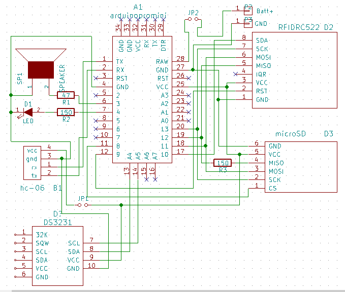
I have additionally added an SD module for recording splits and a Bluetooth module to the circuit so that the station can be connected to a telephone or computer for receiving or transmitting data.
While the scheme and firmware is not yet sufficiently optimized and implemented while from the modules on the knee. In the future, it is planned to modify for more convenient use.
At the moment, data processing is carried out in a semi-manual way by sorting the resulting CSV files. The system is very flexible and can be easily configured for any competition, to implement data preprocessing in the gateway station in a convenient way in different cases. For the future, there are plans to write software to automate data processing.
Conclusion
I am new to programming and developing electronic devices and have been doing this for less than a year. Therefore, the code and circuit solutions are quite possibly far from optimal or completely incorrect. I would be very happy to criticism, the entire project is freely available on the githab .
I also want to thank those who have already helped with advice and became interested in development.
All Articles