今日は、Q-touchライブラリを使用してタッチボタンとスライダーを処理する例を示します。
サイクルの3番目の部分では、約束どおり、これらのセンサーからのデータはModBus TCPパッケージに「パック」され、Wi-Fi経由でオフィスの照明制御システムに送信されます。
始めるために、どのようなQ-touchを見つけましょう。 これは、抵抗性タッチボタンとスライダーの処理技術のAtmelovsk実装であり、操作を簡素化するライブラリが付属しています。 さらに、すべてのSAMDマイクロコントローラーには、ハードウェアQタッチコントローラー(いわゆる周辺タッチコントローラー(PTC))があります。 これにより、マイクロコントローラーの使用ピン数とコンピューティングコアの負荷を最小限に抑えることができます。
センサーとして、 ATQT1-XPRO拡張モジュールを使用します。これは、前の記事で既に述べたように、Xplained Proシリーズの任意のデバッグボードにインストールできます。
Qtouchテクノロジーは、ボタン、スライダー、ローター、近接検知のセンサーの種類をサポートしています。

QtouchおよびQMatrixテクノロジー
QTouchは独自の静電容量の測定に基づいており、QMatrixはジョイントの測定に基づいています。
固有の静電容量を使用した測定は、未知の静電容量の敏感な電極を既知の電位に充電することを意味します。 結果の電荷は測定回路に転送されます。 電荷と転送のサイクルを使用して、敏感なプレートの静電容量を測定できます。
結合容量を使用した測定は、2つの電極を使用して実行されます。 電極の1つはエミッタとして機能し、バーストモードでロジックパルスによって送信される電荷を受け取ります。 2番目の電極はレシーバーとして機能し、タッチパネルを構成する誘電体を介してエミッターと通信します。 指がパネルに触れると、ジョイントフィールドが減少し、タッチが検出されます。
| Qtouch | QMatrix |
|---|---|
| 自己能力 | 共同能力 |
| 堅牢でシンプルな電極設計 | 明確に定義されたクリック検出エリア |
| 少数のセンサーに最適 | 多数のセンサー(10以上)に最適 |
| 遠距離でのアプローチの適切な定義 | 湿度と環境によく適応 |
| 理論的にはあらゆる形態の電極 | パッシブトラッキング-より長いパスが可能 |
| 感度調整が簡単 | ノイズと地面のノイズによく適応 |
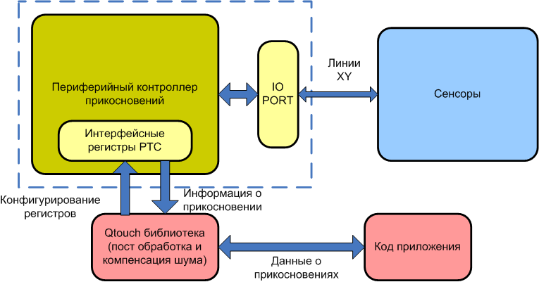
SAMD20および21シリーズのコントローラーには、QTouch / QMatrixテクノロジーが統合されています。 それを担当する特別なユニットは、ペリフェラルタッチコントローラー(PTC)です。 システム全体の運用スキームを下図に示します。
プロジェクトを作成する
新しい周辺機器を開発するには、サンプルプロジェクトを使用すると非常に便利です。 また、QTouchには、開発を視覚化する特別なQTouch Composerプラグインもあります。 ただし、タッチボタンを既存のプロジェクトに統合する必要がある場合は、アクションと設定のシーケンス全体を理解する必要があります。 さあ、やってみましょう。
ライブラリの一般的なスキームをブロック図に示します。

PTCおよびRTCウィザードを使用してプロジェクトに追加します。
構成はファイルtouch_config_samd.hで構成されます。 主なパラメーターを見てみましょう。
最初に、タッチを決定する方法を選択する必要があります:自分の能力または関節。 選択は、対応する定数の値を設定することにより実行されます。
#define DEF_TOUCH_MUTLCAP (1u) #define DEF_TOUCH_SELFCAP (0u)
変換を完了するためのPTCコントローラーからの割り込みの優先度には、0〜3の値を設定できます(0が最高の優先度です)。 そして、定義の助けを借りてインストールされます:
#define DEF_TOUCH_PTC_ISR_LVL (1u)
上記のように、ジョイント静電容量を使用してタッチを決定するには、XとYの2つのラインが必要です。Samd21にはXとYの16ラインがあります。この場合(拡張カードでのデバッグを使用) /ロータースタート。 出力のペアを指定する順序により、チャネル番号が設定されます。 ローター/スライダーの場合、すべてのチャンネルに同じYラインを使用することが不可欠です。 行は、対応する定義を使用して指定されます。
#define DEF_MUTLCAP_NODES X(8), Y(10), X(9), Y(10), X(2), Y(12), X(3), Y(12), \ X(8), Y(12), X(9), Y(12), X(2), Y(13), X(3), Y(13), \ X(8), Y(13), X(9), Y(13)
チャネルの数を示します(ボタンの場合、常に1チャネル、ローター/スライダーの場合は3〜8)。 私たちの場合、2つのボタンが使用され、ローターとスライダーごとに4つのチャネルがあり、合計で10チャネルです。
#define DEF_MUTLCAP_NUM_CHANNELS (10) /* Total number of channels */
センサーの数を示します(合計4つのボタンが2つ、スライダーが1つ、ローターが1つあります)。
#define DEF_MUTLCAP_NUM_SENSORS (4) /* Total number of sensors */
ローター/センサーの数を示します(スライダーが1つ、ローターが合計2つあります)。
#define DEF_MUTLCAP_NUM_ROTORS_SLIDERS (2) /* Number of rotor sliders */
変換パラメーターの指定に移ります。
フィルタリングのレベルは、変換の精度と速度に影響します。 レベルが高いほど(1から64)、1回の変換でより多くのサンプルが落ち、ノイズ/信号比は改善されますが、変換時間は長くなります。
#define DEF_MUTLCAP_FILTER_LEVEL FILTER_LEVEL_32 /* Filter level */
センサーからの信号増幅は、チャンネルごとに調整されます。 値の範囲は1〜32です。
#define DEF_MUTLCAP_GAIN_PER_NODE GAIN_1, GAIN_1, GAIN_1, GAIN_1, GAIN_1, \ GAIN_1, GAIN_1, GAIN_1, GAIN_1, GAIN_1
ポーリング期間をミリ秒単位で設定します。
#define DEF_TOUCH_MEASUREMENT_PERIOD_MS 20u
メカニカルボタンに関しては、タッチボタンにアンチバウンスのようなものが用意されています。 それは、ボタン/ローター/スライダーのタッチを検出するために、信号レベルがしきい値を超えなければならない測定サイクルの数を示すという事実にあります。
#define DEF_MUTLCAP_DI 4u
ある物体がセンサーに長時間触れていることがあります。 この場合、新しい動作条件を考慮してしばらくしてからセンサーを再較正する必要があります。 再キャリブレーションが発生するまでの時間を設定するには、特別な定数が使用されます。 時間は200ミリ秒単位で設定されます(つまり、値5は1秒に対応します)。 時間が0に設定されている場合、自動再キャリブレーションは実行されません。
#define DEF_MUTLCAP_MAX_ON_DURATION 0u
Qtouch Analyzerのデバッグ情報の出力を有効または無効にできます。
<cut />#define DEF_TOUCH_QDEBUG_ENABLE 0u
いくつかの奇妙な理由により、Atmelには(他の周辺機器と同様に)標準のPTC初期化関数といくつかの必要な定数の定義が含まれていませんでした。 したがって、これはすべて独立して行う必要があります。 今何をしますか。
まず、RTCを中断すると、ボタンの操作がテストされるため、RTCを初期化する必要があります。 RTCを構成し、コールバックを登録し、コールバックのコードを記述します。 RTCは、ボタンの読み取り間隔と同じだけのmsが経過した場合、1 msごとに割り込みを生成し、メインでチェックされる適切なフラグを設定します。
必要な広告:
タイマー機能
// RTC Interrupt timing definition #define TIME_PERIOD_1MSEC 33u /* ! QTouch Library Timing info. */ touch_time_t touch_time; volatile uint16_t touch_time_counter = 0u; struct rtc_module rtc_instance; : void rtc_overflow_callback(void) { /* Do something on RTC overflow here */ if(touch_time_counter == touch_time.measurement_period_ms) { touch_time.time_to_measure_touch = 1u; touch_time.current_time_ms = touch_time.current_time_ms + touch_time.measurement_period_ms; touch_time_counter = 0u; } else { touch_time_counter++; } } void configure_rtc_callbacks(void) { /* register callback */ rtc_count_register_callback(&rtc_instance, rtc_overflow_callback, RTC_COUNT_CALLBACK_OVERFLOW); /* Enable callback */ rtc_count_enable_callback(&rtc_instance,RTC_COUNT_CALLBACK_OVERFLOW); } void configure_rtc_count(void) { struct rtc_count_config config_rtc_count; rtc_count_get_config_defaults(&config_rtc_count); config_rtc_count.prescaler = RTC_COUNT_PRESCALER_DIV_1; config_rtc_count.mode = RTC_COUNT_MODE_16BIT; config_rtc_count.continuously_update = true; /* initialize rtc */ rtc_count_init(&rtc_instance,RTC,&config_rtc_count); /* enable rtc */ rtc_count_enable(&rtc_instance); } void timer_init(void) { /* Configure and enable RTC */ configure_rtc_count(); /* Configure and enable callback */ configure_rtc_callbacks(); /* Set Timer Period */ rtc_count_set_period(&rtc_instance,TIME_PERIOD_1MSEC); }
次に、PTC自体を構成する必要があります。 まず、必要な構造を追加します。
PTCの構造
static touch_mutlcap_config_t mutlcap_config = { DEF_MUTLCAP_NUM_CHANNELS, /* Mutual Cap number of channels. */ DEF_MUTLCAP_NUM_SENSORS, /* Mutual Cap number of sensors. */ DEF_MUTLCAP_NUM_ROTORS_SLIDERS, /* Mutual Cap number of rotors and sliders. */ /* Mutual Cap GLOBAL SENSOR CONFIGURATION INFO. */ { DEF_MUTLCAP_DI, /* uint8_t di; Sensor detect integration (DI) limit. */ /* Interchanging Negative and Positive Drift rate, since Signal increases on Touch. */ DEF_MUTLCAP_ATCH_DRIFT_RATE, /* uint8_t neg_drift_rate; Sensor negative drift rate. */ DEF_MUTLCAP_TCH_DRIFT_RATE, /* uint8_t pos_drift_rate; Sensor positive drift rate. */ DEF_MUTLCAP_MAX_ON_DURATION, /* uint8_t max_on_duration; Sensor maximum on duration. */ DEF_MUTLCAP_DRIFT_HOLD_TIME, /* uint8_t drift_hold_time; Sensor drift hold time. */ DEF_MUTLCAP_ATCH_RECAL_DELAY, /* uint8_t pos_recal_delay; Sensor positive recalibration delay. */ DEF_MUTLCAP_CAL_SEQ1_COUNT, DEF_MUTLCAP_CAL_SEQ2_COUNT, DEF_MUTLCAP_ATCH_RECAL_THRESHOLD, /* recal_threshold_t recal_threshold; Sensor recalibration threshold. */ }, { mutlcap_gain_per_node, /* Mutual Cap channel gain setting. */ DEF_MUTLCAP_FREQ_MODE, /* Mutual Cap noise counter measure enable/disable. */ DEF_MUTLCAP_CLK_PRESCALE, DEF_MUTLCAP_SENSE_RESISTOR, DEF_MUTLCAP_CC_CAL_CLK_PRESCALE, DEF_MUTLCAP_CC_CAL_SENSE_RESISTOR, mutlcap_freq_hops, DEF_MUTLCAP_FILTER_LEVEL, /* Mutual Cap filter level setting. */ DEF_MUTLCAP_AUTO_OS, /* Mutual Cap auto oversamples setting.*/ }, mutlcap_data_blk, /* Mutual Cap data block index. */ PRIV_MUTLCAP_DATA_BLK_SIZE, /* Mutual Cap data block size. */ mutlcap_xy_nodes, /* Mutual Cap channel nodes. */ DEF_MUTLCAP_QUICK_REBURST_ENABLE, DEF_MUTLCAP_FILTER_CALLBACK /* Mutual Cap filter callback function pointer. */ }; touch_config_t touch_config = { &mutlcap_config, /* Pointer to Mutual Cap configuration structure. */ NULL, DEF_TOUCH_PTC_ISR_LVL, /* PTC interrupt level. */ };
マクロ:
#define GET_MUTLCAP_SENSOR_STATE(SENSOR_NUMBER) p_mutlcap_measure_data-> \ p_sensor_states[(SENSOR_NUMBER / \ 8)] & (1 << (SENSOR_NUMBER % 8))
定義:
#define DEF_MUTLCAP_CAL_SEQ1_COUNT 8 #define DEF_MUTLCAP_CAL_SEQ2_COUNT 4 #define DEF_MUTLCAP_CC_CAL_CLK_PRESCALE PRSC_DIV_SEL_8 #define DEF_MUTLCAP_CC_CAL_SENSE_RESISTOR RSEL_VAL_100 #define DEF_MUTLCAP_QUICK_REBURST_ENABLE 1u #define PTC_APBC_BITMASK (1u << 19u)
変数:
static uint8_t mutlcap_data_blk[PRIV_MUTLCAP_DATA_BLK_SIZE]; uint16_t mutlcap_xy_nodes[DEF_MUTLCAP_NUM_CHANNELS * 2] = {DEF_MUTLCAP_NODES}; gain_t mutlcap_gain_per_node[DEF_MUTLCAP_NUM_CHANNELS]= {DEF_MUTLCAP_GAIN_PER_NODE}; freq_hop_sel_t mutlcap_freq_hops[3u] = {DEF_MUTLCAP_HOP_FREQS};
PTCタイミング設定機能:
void touch_configure_ptc_clock(void) { struct system_gclk_chan_config gclk_chan_conf; system_gclk_chan_get_config_defaults(&gclk_chan_conf); gclk_chan_conf.source_generator = GCLK_GENERATOR_3; system_gclk_chan_set_config(PTC_GCLK_ID, &gclk_chan_conf); system_gclk_chan_enable(PTC_GCLK_ID); system_apb_clock_set_mask(SYSTEM_CLOCK_APB_APBC, PTC_APBC_BITMASK); }
センサー構成:
touch_ret_t touch_sensors_config(void) { touch_ret_t touch_ret = TOUCH_SUCCESS; sensor_id_t sensor_id; touch_ret = touch_mutlcap_sensor_config(SENSOR_TYPE_KEY, CHANNEL_0, CHANNEL_0, NO_AKS_GROUP, 20u, HYST_6_25, RES_8_BIT,0, &sensor_id); if (touch_ret != TOUCH_SUCCESS) while (1); touch_ret = touch_mutlcap_sensor_config(SENSOR_TYPE_KEY, CHANNEL_1, CHANNEL_1, NO_AKS_GROUP, 20u, HYST_6_25, RES_8_BIT,0, &sensor_id); if (touch_ret != TOUCH_SUCCESS) while (1); touch_ret = touch_mutlcap_sensor_config(SENSOR_TYPE_ROTOR, CHANNEL_6, CHANNEL_9, NO_AKS_GROUP, 20u, HYST_6_25, RES_8_BIT,0, &sensor_id); if (touch_ret != TOUCH_SUCCESS) while (1); touch_ret = touch_mutlcap_sensor_config(SENSOR_TYPE_SLIDER, CHANNEL_2, CHANNEL_5, NO_AKS_GROUP, 20u, HYST_6_25, RES_8_BIT,0, &sensor_id); if (touch_ret != TOUCH_SUCCESS) while (1); return (touch_ret); }
センサーおよび一般パラメーターの初期化
touch_ret_t touch_sensors_init(void) { touch_ret_t touch_ret = TOUCH_SUCCESS; /* Setup and enable generic clock source for PTC module. */ touch_configure_ptc_clock(); touch_time.measurement_period_ms = DEF_TOUCH_MEASUREMENT_PERIOD_MS; /* Initialize touch library for Mutual Cap operation. */ touch_ret = touch_mutlcap_sensors_init(&touch_config); if (touch_ret != TOUCH_SUCCESS) { while (1u); /* Check API Error return code. */ } #if DEF_TOUCH_QDEBUG_ENABLE == 1 QDebug_Init(); #endif /* configure the touch library sensors. */ touch_ret = touch_sensors_config(); if (touch_ret != TOUCH_SUCCESS) { while (1u); /* Check API Error return code. */ } /* Auto Tuning setting for calibration. * * AUTO_TUNE_PRSC: When Auto tuning of pre-scaler is selected * the PTC uses the user defined internal series resistor setting * (DEF_MUTLCAP_SENSE_RESISTOR) and the pre-scaler is adjusted * to slow down the PTC operation to ensure full charge transfer. * * AUTO_TUNE_RSEL: When Auto tuning of the series resistor is * selected the PTC runs at user defined pre-scaler setting speed * (DEF_MUTLCAP_CLK_PRESCALE) and the internal series resistor is * tuned automatically to the optimum value to allow for full * charge transfer. * * AUTO_TUNE_NONE: When manual tuning option is selected (AUTO_TUNE_NONE), * the user defined values of PTC pre-scaler and series resistor is used * for PTC operation as given in DEF_MUTLCAP_CLK_PRESCALE and * DEF_MUTLCAP_SENSE_RESISTOR * */ touch_ret = touch_mutlcap_sensors_calibrate(AUTO_TUNE_RSEL); if (touch_ret != TOUCH_SUCCESS) { while (1u); /* Check API Error return code. */ } return (touch_ret); }
測定終了時の測定および割り込みハンドラー
void touch_mutlcap_measure_complete_callback( void ) { #if DEF_TOUCH_QDEBUG_ENABLE == 1 /* Send out the Touch debug information data each time when Touch * measurement process is completed . * The Touch Signal and Touch Delta values are always sent. * Touch Status change, Rotor-Slider Position change and Sensor * Reference * values can be optionally sent using the masks below. */ QDebug_SendData( TOUCH_CHANNEL_REF_CHANGE | TOUCH_ROTOR_SLIDER_POS_CHANGE | TOUCH_STATUS_CHANGE ); /* QT600 two-way QDebug communication application Example. */ /* Process any commands received from QTouch Studio. */ QDebug_ProcessCommands(); #endif if (!(p_mutlcap_measure_data->acq_status & TOUCH_BURST_AGAIN)) { /* Set the Mutual Cap measurement done flag. */ p_mutlcap_measure_data->measurement_done_touch = 1u; } } touch_ret_t touch_sensors_measure(void) { touch_ret_t touch_ret = TOUCH_SUCCESS; if (touch_time.time_to_measure_touch == 1u) { /* Start a touch sensors measurement process. */ touch_ret = touch_mutlcap_sensors_measure( touch_time.current_time_ms, NORMAL_ACQ_MODE, touch_mutlcap_measure_complete_callback); if ((touch_ret != TOUCH_ACQ_INCOMPLETE) && (touch_ret == TOUCH_SUCCESS)) { touch_time.time_to_measure_touch = 0u; } else if ((touch_ret != TOUCH_SUCCESS) &&(touch_ret != TOUCH_ACQ_INCOMPLETE)) { while (1); /* Reaching this point can be due to - * 1. The api has retured an error due to a invalid * input parameter. * 2. The api has been called during a invalid Touch * Library state. */ } } return (touch_ret); }
メインでは、RTCタイマーの初期化、PTCの初期化、スリープモードの構成(必要な場合)、およびグローバル割り込みの有効化が必要です。
メインでの初期化
system_interrupt_enable_global();
//タイマーを初期化します。 (RTC実際に
timer_init();
// QTouchライブラリを初期化し、タッチセンサーを構成します。
touch_sensors_init();
NVMCTRL-> CTRLB.bit.SLEEPPRM = 3;
system_set_sleepmode(SYSTEM_SLEEPMODE_STANDBY);
//タイマーを初期化します。 (RTC実際に
timer_init();
// QTouchライブラリを初期化し、タッチセンサーを構成します。
touch_sensors_init();
NVMCTRL-> CTRLB.bit.SLEEPPRM = 3;
system_set_sleepmode(SYSTEM_SLEEPMODE_STANDBY);
最も単純なケースでは、ボタンのタッチとスライダーの位置がLEDで示されているとします。 ローターには触れません。
(1)では、(必要に応じて)スリープ状態に陥る機能、タッチを処理するためのタッチと点火を処理する機能を追加する必要があります:
whileのコード(1)
// Goto STANDBY sleep mode, unless woken by timer or PTC interrupt. system_sleep(); // Start touch sensor measurement, if touch_time.time_to_measure_touch flag is set by timer. touch_sensors_measure(); if ((p_mutlcap_measure_data->measurement_done_touch == 1u)) { p_mutlcap_measure_data->measurement_done_touch = 0u; // Get touch sensor states button1_state = GET_MUTLCAP_SENSOR_STATE(0); button2_state = GET_MUTLCAP_SENSOR_STATE(1); rotor_state = GET_MUTLCAP_SENSOR_STATE(2); slider_state = GET_MUTLCAP_SENSOR_STATE(3); if (button1_state) { if(button_pressed!=1) { port_pin_set_output_level(LED_8_PIN, 0); button_pressed=1; } } else { port_pin_set_output_level(LED_8_PIN, 1); if (button_pressed==1) { button_pressed=0; } } if (button2_state) { if(button_pressed!=2) { port_pin_set_output_level(LED_9_PIN, 0); button_pressed=2; } } else { port_pin_set_output_level(LED_9_PIN, 1); if (button_pressed==2) { button_pressed=0; } } // Clear all slider controlled LEDs port_pin_set_output_level(LED_0_PIN, 1); port_pin_set_output_level(LED_1_PIN, 1); port_pin_set_output_level(LED_2_PIN, 1); port_pin_set_output_level(LED_3_PIN, 1); port_pin_set_output_level(LED_4_PIN, 1); port_pin_set_output_level(LED_5_PIN, 1); port_pin_set_output_level(LED_6_PIN, 1); port_pin_set_output_level(LED_7_PIN, 1); // If slider is activated if(slider_state) { // Parse slider position slider_position = GET_MUTLCAP_ROTOR_SLIDER_POSITION(1); slider_position = slider_position >> 5u; switch(slider_position) { case 0: port_pin_set_output_level(LED_0_PIN, 0); break; case 1: port_pin_set_output_level(LED_0_PIN, 0); port_pin_set_output_level(LED_1_PIN, 0); break; case 2: port_pin_set_output_level(LED_0_PIN, 0); port_pin_set_output_level(LED_1_PIN, 0); port_pin_set_output_level(LED_2_PIN, 0); break; case 3: port_pin_set_output_level(LED_0_PIN, 0); port_pin_set_output_level(LED_1_PIN, 0); port_pin_set_output_level(LED_2_PIN, 0); port_pin_set_output_level(LED_3_PIN, 0); break; case 4: port_pin_set_output_level(LED_0_PIN, 0); port_pin_set_output_level(LED_1_PIN, 0); port_pin_set_output_level(LED_2_PIN, 0); port_pin_set_output_level(LED_3_PIN, 0); port_pin_set_output_level(LED_4_PIN, 0); break; case 5: port_pin_set_output_level(LED_0_PIN, 0); port_pin_set_output_level(LED_1_PIN, 0); port_pin_set_output_level(LED_2_PIN, 0); port_pin_set_output_level(LED_3_PIN, 0); port_pin_set_output_level(LED_4_PIN, 0); port_pin_set_output_level(LED_5_PIN, 0); break; case 6: port_pin_set_output_level(LED_0_PIN, 0); port_pin_set_output_level(LED_1_PIN, 0); port_pin_set_output_level(LED_2_PIN, 0); port_pin_set_output_level(LED_3_PIN, 0); port_pin_set_output_level(LED_4_PIN, 0); port_pin_set_output_level(LED_5_PIN, 0); port_pin_set_output_level(LED_6_PIN, 0); break; case 7: port_pin_set_output_level(LED_0_PIN, 0); port_pin_set_output_level(LED_1_PIN, 0); port_pin_set_output_level(LED_2_PIN, 0); port_pin_set_output_level(LED_3_PIN, 0); port_pin_set_output_level(LED_4_PIN, 0); port_pin_set_output_level(LED_5_PIN, 0); port_pin_set_output_level(LED_6_PIN, 0); port_pin_set_output_level(LED_7_PIN, 0); break; default: port_pin_set_output_level(LED_0_PIN, 1); port_pin_set_output_level(LED_1_PIN, 1); port_pin_set_output_level(LED_2_PIN, 1); port_pin_set_output_level(LED_3_PIN, 1); port_pin_set_output_level(LED_4_PIN, 1); port_pin_set_output_level(LED_5_PIN, 1); port_pin_set_output_level(LED_6_PIN, 1); port_pin_set_output_level(LED_7_PIN, 1); break; } } }//measurement done flag
コンパイル、記入、お楽しみください。