Create isometric 2D levels using the Tilemap system

Unity 2018.3 introduced support for isometric tile maps, very similar to the hexagon tile maps support that was added in version 2018.2. New Tilemap features allow you to quickly and efficiently create 2D environments based on the isometric and hexagonal grids that were used in many classic games, including the first parts of Diablo and Fallout, Civilization, Age of Empires, and many others.
Both systems are based on the already existing Tilemap system, which appeared in Unity 2017.2, and today it is just as easy to work with them! In addition, they have native integration with Editor. In future versions of Unity, they can be ported to the package manager.
If you are interested in experimenting with these systems, we created a pre-prepared Isometric Starter Kit project with an animated character and several environment tilesets. You can download it here .
Project Settings for Isometric Tilemap
Before we get started with Tilemap, it's important to set up the project correctly. Isometric Tilemap works with two-dimensional sprites and uses the right sorting of rendering to create the illusion of an isometric map with a top view. We need to make the tiles farther from the viewer first drawn, and the closer ones on top of them.
You can use the Unity function called Custom Axis Sort to adjust the rendering order of 2D objects on the screen. This parameter can be set either for the camera (currently this method is standard for Scriptable Render Pipelines, including LWRP and HDRP), or globally, at the project level.
To set Custom Axis Sort at the project level, go to Edit> Project Settings> Graphics . In the Camera Settings section, you will see the Transparency Sort Mode drop-down menu, as well as the X, YZ value options for Transparency Sort Axis.
By default, Transparency Sort Axis sets the XYZ axes to (0, 0, 1). However, all of our 2D tiles are actually on the same Z plane. Therefore, to determine which tiles are in front or behind, you need to use not depth, but height. Tiles located higher on the screen will be sorted by lower ones. To sort tiles by height, change the Transparency Sort Mode value to Custom and set Transparency Sort Axis to (0, 1, 0).

To learn more about how this works, you can read the corresponding page on 2D sorting in the Unity documentation.
In some cases, it may also be necessary to change the Transparency Sort Axis value to Z. We will talk more about this below.
Tile Card Types
The Tilemap system consists of several interacting components. The first two are the Grid and Tilemap game objects. To create a Grid, just right-click anywhere in the Hierarchy, go to the 2D Object, and select the type of Tilemap that you want to use. By default, each new Grid is created with one child Tilemap game object of the corresponding type. The following types of Tilemap currently exist:
Tilemap - creates rectangular Grid and Tilemap. An example of the use of this Tilemap can be seen in the 2D Game Kit of the Unity engine.
Hexagonal Point Top Tilemap - creates a Grid and Tilemap from hexagons, in which one of the vertices of each hexagon is directed upwards.
Hexagonal Flat Top Tilemap is another type of Grid of hexagons, in which at the top of the hexagon there is a face parallel to the top edge of the screen.
The last two types, Isometric and Isometric Z as Y , create two different implementations of the isometric grid. The difference between them appears when simulating different levels of tile heights, for example, when there is a high platform at the isometric level.
If you want to create separate Tilemap game objects for each level of tile heights, then it is better to use the usual Isometric Tilemap type. It simplifies the process of creating automatic collision forms, but has less flexibility when working with elevations between tiles, because all tiles on the same layer should be on the same “plane”.
In the case of Isometric Z as Y Tilemap , the Z position value of each tile works in conjunction with the Transparency Axis Sort parameter, making the tiles appear stacked on top of each other. When drawing on a Z as Y Tilemap, we dynamically change the Z parameter of the brush to switch between different heights. To render Z as Y Tilemap correctly , an additional Z value is required in the Transparency Sort Axis with Custom mode.
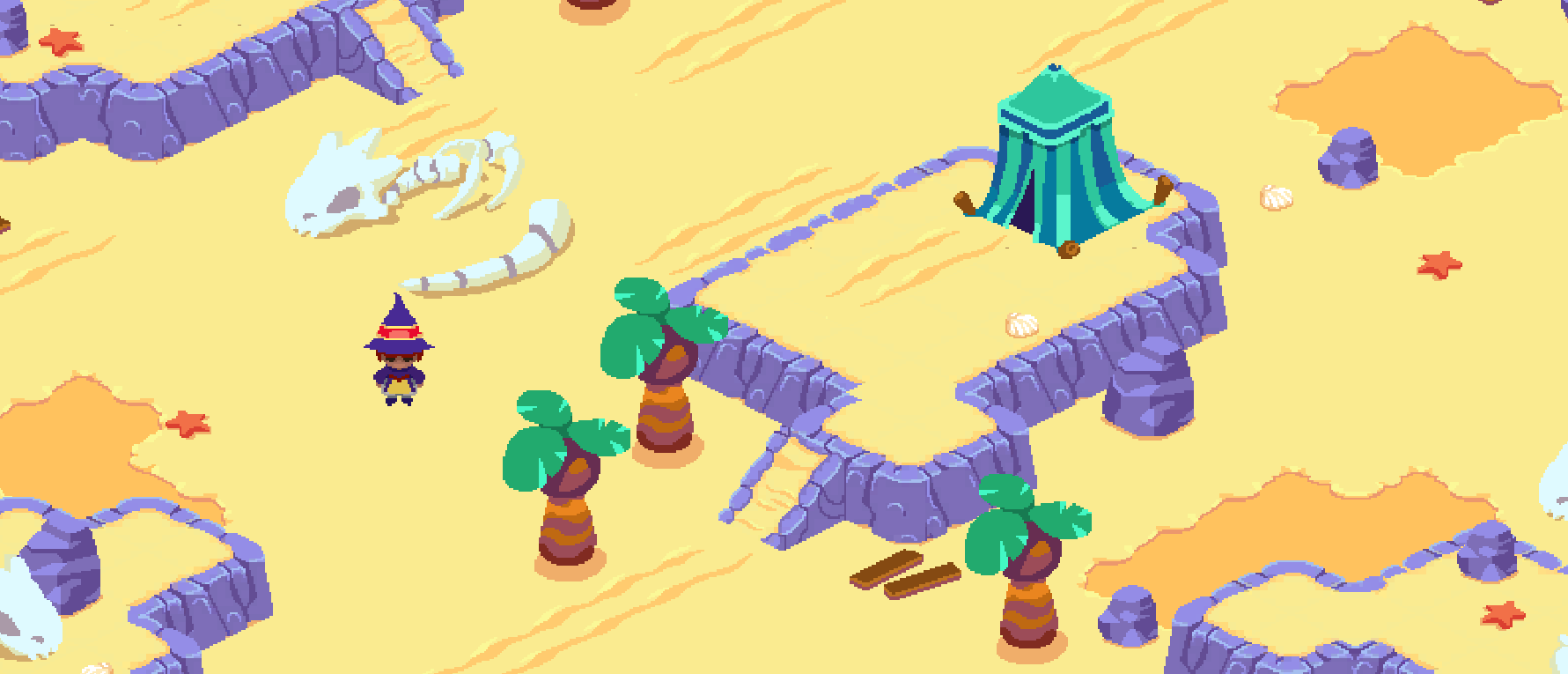
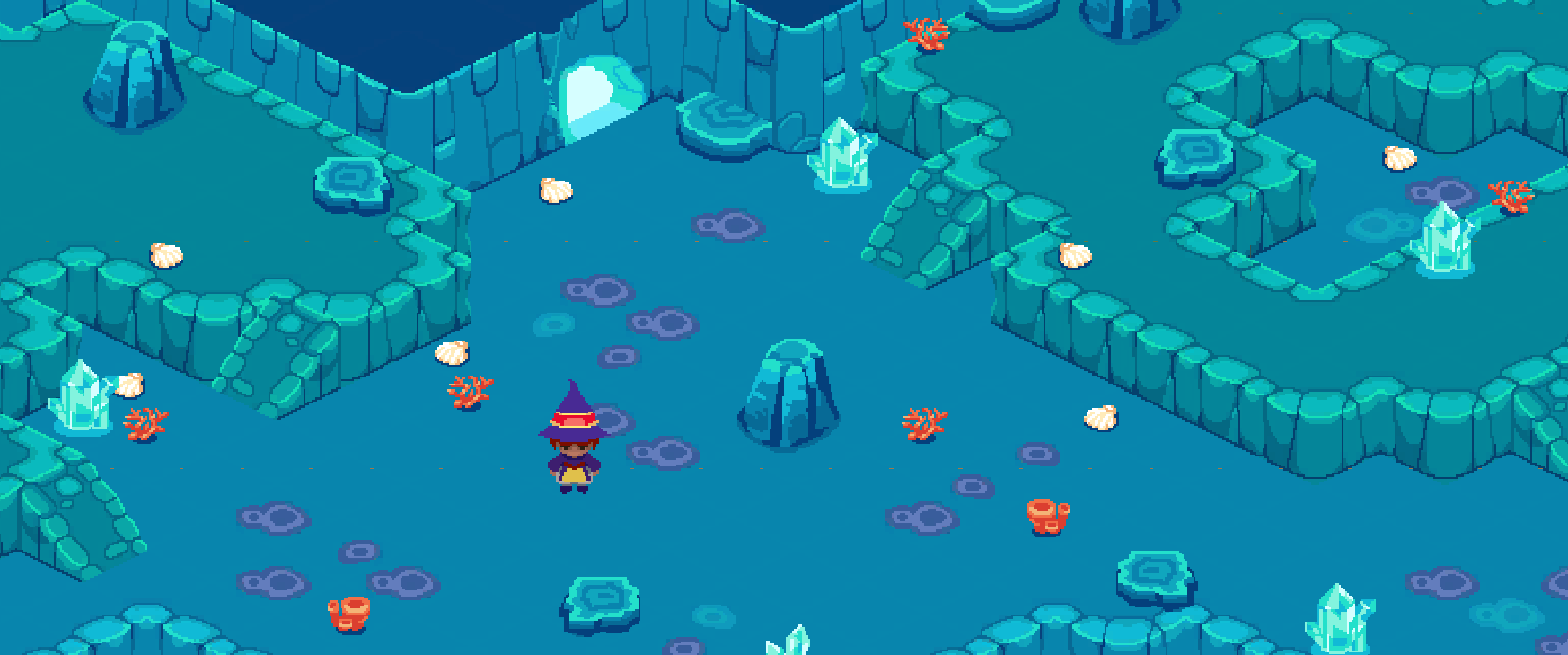
Note: The assets shown in the screenshots are taken from the Temple tile of the Isometric Starter Kit project. They are completely free, so you can use them to create your own environments!
Think of the Grid as an “easel” on which all Tilemap game objects reside. And they, in turn, are essentially a canvas on which we will draw tiles. To start drawing on Tilemap, we also need a brush and a palette. All tile assets are located on the Tile Palette, from which they can be selected using the brush tool and start drawing.
To create a Tile Palette, choose Window> 2D> Tile Palette. In the upper left drop-down menu, select “Create New Palette”. Make sure that the appropriate mesh type is selected. In the example, I will use the usual Isometric Tilemap, as well as assets from the Isometric Starter Kit project. We will specify Manual as the cell size of the palette (cell size) in order to be able to resize isometric tiles. In this case, I know that the sizes of my tiles correspond to a grid with a cell size of 1 by X and 0.5 by Y; however, they depend on the resolution selected when importing the values of pixels per unit and the sizes of the assets - in fact, on the isometric angle that the tiles are rotated.

Note on importing assets
You may not know which import options and tile card size are best for your assets. There is a general rule that you can follow: first you need to look at the resolution of tiles. Typically, isometric tile blocks are larger in height than in width; “Flat” tiles (which look more like a plane than a cube) are wider than high. However, the width between them will always be the same. Therefore, if you want the tiles to occupy exactly one Unity unit of measurement, then set the Pixels Per Unit in the tile import settings to a value equal to their width in pixels. In some cases this value will have to be changed, usually in the direction of decreasing (or increasing the resolution of assets); this can be useful if you want to recreate an effect in which some tiles seem to occupy more than one grid cell and overlap adjacent tiles.

To determine the correct grid value by Y for tiles, take the height of the base (or vertex) of one tile, and divide it by the width. This will give you the value of Y relative to X, given that X is 1. Let's look at some examples:

In the pixel art assets we use for this project, all base tiles are 32 pixels high and 64 pixels wide. Therefore, the grid size in Y will be equal to 0.5. The second block in the image is taken from the Golden Skull Studios asset package; You can see it here . The example tile has been reduced, but the original assets are 128 pixels wide. The base of the tile is approximately 66 pixels, which gives a grid size of Y equal to 66/128, i.e. approximately 0.515 units.
The basic process of working with Tilemap
Having decided on the correct Grid sizes, we will add several tiles to our palette. Just grab one of the tile sprites and drag it into the Tile Palette window. This will create the Tile Asset. It contains information about the tile itself, for example, the sprites it uses, the hue and type of the generated collider. If you need to see detailed information about the palette tile, select the Select (S) tool at the top of the Tile Palette window and click on this tile. Notice that the Inspector can see which Tile asset it refers to.
To draw a new Tile by Tilemap, select the Brush tool (B) and click on the Tile in the Palette. After that, you can draw with the selected tile in the scene window. There are other drawing tools like Eraser (D), Box Fill (U), Flood Fill (G) and Tile Picker (I).
Sometimes you need to change the location of tiles on the palette itself. Immediately below the toolbar there is an Edit button. If you click on it, the palette editing mode will turn on, in which the tools affect the Tile Palette itself. Do not forget to exit this mode after making the necessary changes.
Tilemap Renderer Modes
In some cases, tiles of different types may not be sorted correctly, despite being on the same Tilemap, as in this example:

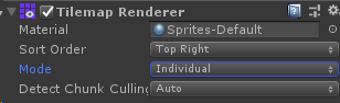
This is determined by the Mode parameter of the Tilemap Renderer component. By default, Mode is Chunk.
Chunk mode is effective in reducing Tilemap asset consumption. Instead of rendering each tile individually, it renders them in a single pass as a large block. However, this mode has two main disadvantages. First, it does not support dynamic sorting with other 2D objects in the scene. This means that if the Tilemap is in Chunk mode, then it will not be able to dynamically sort in front of or behind other objects, for example, characters - only one or the other will be visible at a time, and this depends on the Order in Layer parameter. However, it is still extremely effective at optimizing the game and can be used to batch render large areas of terrain.
However, this does not save us from the problem of incorrect sorting of different tiles. To batch render tiles taken from two or more different sprites (e.g. textures), the sprites must be combined into a single Sprite Atlas asset.
To create Sprite Atlas, select Assets> Create> Sprite Atlas . Sprite Atlas options have a list of Objects for Packing . Just drag and drop into it all the tiles that you want to render in batches, and specify the appropriate import parameters, usually matching the parameters of individual sprites.
After that, the tiles will be sorted correctly; but they will only be visible in Play mode or during game execution.
Therefore, during the editing process, it is better to select Individual mode for Tilemap Renderer. In this mode, each sprite will be sorted separately; this means that they will render correctly even outside the Play mode, which is very useful when editing a level. After completing the creation of the level structure, you can switch the Tilemap Renderer mode to Chunk again at any time.
Individual rendering mode is also useful when you need to add objects such as trees, objects and higher plots of land that should be dynamically sorted with characters or with each other. In this post we will enable the Individual mode for all Tilemap.

Using Multiple Tilemap
Sometimes it is required to use several Tilemap on one Grid. In the case of isometric and hexagonal Tilemap, it is useful to be able to add to the level of the item aligned on the grid or tiles that seem higher than the first layer.
To connect another Tilemap to the grid, right-click on the Grid game object and create a new Tilemap of the appropriate type.
To start drawing on the new Tilemap, go back to the Tile Palette window and change the Active Tilemap under the main toolbar.
Adding Raised Areas
There are two main ways to add elevated areas to levels. Choosing the right one usually depends on the type of Tilemap selected. We will consider each of the cases.
In addition, we prepared a short video on this topic, which demonstrates these approaches using the usual Isometric Tilemap as well as adding collision areas to tiles. Watch the video if you want to briefly understand both of these ways:
Using a regular Isometric Tilemap
For regular Isometric Tilemap, you can simply create a new Tilemap from the same Grid and assign Order in Layer a higher value. You can then change the Tile Anchor parameter so that the new layer is snapped to a higher point in the same grid.
My lower level Tilemap for X and Y has Tile Anchor set to (0, 0). I want the new layer to be drawn one unit higher, so I will change the anchor point of the new Tilemap to (1, 1). I will also set Order in Layer to 1 — one more than the base level.
Now you can change the active Tilemap to having a second level of height and start drawing.

Using Z as Y Isometric Tilemap
It can sometimes be useful to simulate different heights with one Tilemap. In such a case, Z as Y Isometric Tilemap and Grid can be used.
In the case of Z as Y Tilemap, the Z value of each tile has an additional effect on the order in which tiles are rendered. We can change the value of Z tiles when drawing them using the Z Position parameter of the brush at the bottom of the Tile Palette (as well as using the hot keys "+" and "-"):

However, in order for the Z value to influence correctly and the tiles to be sorted correctly, you need to go back to the Custom Axis Sort value and add the Z effect. The number used here is directly related to how Unity converts the positions of the isometric grid cells into values in world space.
For example, a grid with dimensions according to XYZ of (1, 0.5, 1) - standard for isometry - will have a sorting value along the Z axis equal to -0.26. If you are interested in how this number is calculated, or if you use a grid with a different cell size, then continue reading to find out how to find the correct Z value for your case.
By setting the correct value for Custom Axis Sort, you can start drawing tiles with different Z values. You can also configure the increments with which the Z value moves the raised tiles up or down, changing the Z size of the Grid, by default, equal to 1.
Z value calculation
There is a general formula that can be used to determine the Z value of axis sorting. First, take the size Y of the grid. If you have not decided on the size of Y yet, see the note on importing assets above. Multiply this value by -0.5, and subtract another 0.01.
According to this formula, a grid having a size of (1, 0.5, 1) will give us a sort value by Z of -0.26. With this sorting value, the tiles of any grid (1, 0.5, 1) will be sorted correctly.
If you want to know more about this value and about calculations, then study the documentation . It explains in detail the work of 2D renderers and what happens when isometric cells are converted to world space values.
Adding Collisions
Now that we have placed some of the tiles over the others, with the help of collisions we can control the areas that the player is able to reach and the transitions between them.
There are many ways to add collisions, but in our case it is required that the player rise and fall along the slope, so it is not so obvious which objects should have colliders. We can set collisions manually using an additional Tilemap.
In this project, we created several sprites corresponding to various shapes that will define areas of collisions. We can draw these shapes on the third Tilemap in places where the player cannot pass. For example, we want a player to be able to climb a rock only on a slope, and not climb directly on it.
We can also add unique material to Tilemap Renderer to give tiles a different shade and distinguish them from the rest of the level.
By placing collision tiles, you can add the Tilemap Collider component to Tilemap collisions. In this case, for each individual tile, colliders are automatically created, determined by the shape of the sprite.
To optimize performance, you can also add the Composite Collider 2D component and check the Used by Composite checkbox of the Tilemap Collider. This will combine all the individual colliders into one large shape.

Adding Items
Adding items to a level is quite simple. You can either manually place item sprites at any desired point in the scene, or attach items to the Tilemap Grid, turning them into separate tiles. Choose yourself which solution suits you best.
In this project, we manually placed several trees at the level. Trees and character have the same Order in Layer, which allows you to dynamically sort the character in front of and behind the trees.
Using the collider, you can specify the point at which the player can go near the tree. This can also be done in several ways.
The first one is shown in the video - just attach a child collider to the object and change its shape as needed.
The second way is to set the Custom Physics Shape for the object in the Sprite Editor. To open the Sprite Editor, select the sprite object and find the Sprite Editor button in the Inspector. In the upper left drop-down menu, switch to the Custom Physics Shape editor. Here you can create polygonal shapes that define the borders of the collider. Having set the physical form, you can attach the Polygon Collider component to the object, and it will correspond to this form.
If you use objects as tiles in Tilemap, you can also use the Grid collider. Select the Tile Asset that matches the item tile (if you don’t remember where to find it, see the “Basic Tilemap Process” section). You will see the Collider Type menu. By default, a sprite is set as the type, that is, an automatically generated collider will use the Physics Shape, which we talked about above. If the type is set to grid. then it will always exactly match the shape of the mesh cell to which the item is attached. Perhaps this is not the most accurate way to implement colliders, but for some types of games it may be useful.
To use colliders for these tiles, select the Tilemap with items and add the Tilemap Collider component.
Using Rule Tiles
Rule Tiles are extremely useful for automating the drawing process with tiles. Rule Tile works like a regular tile, but has an additional list of tiling options. Using these parameters (rules), a tile can automatically choose which sprite to draw depending on neighboring tiles.
Rule Tiles are useful when you do not want to manually select tiles with different turns, for example, when creating a rock or platform. They can also be used to randomize between different variations of the same tile, to avoid repeating patterns, and even to create animated tiles.
Isometric and Hexagonal Rule Tiles are available from the 2D Extras Unity repository on GitHub. It also has many other useful assets for the Tilemap system that are worth exploring.
We added Rule Tiles for each of the tilesets in the Isometric Starter Kit project. Here are some examples from project tiles that you can experiment with:


Further work
Now that you have learned about the device of isometric tile cards in Unity, download the Isometric Starter kit project and try to work with them yourself! If you are a programmer, then you have the opportunity to interact with Tilemap through scripts, you can use it.
For example, by watching this video, you can learn how to implement a simple character controller compatible with Isometric Tilemap:
The graphics for this project were created for Unity by @castpixel ; her other works can be seen here . If you want to learn more about creating 2D games on Unity, then you should learn some great courses from the Learn website . If you are looking for additional resources for experimenting with tile maps, then check out the Unity Asset Store .
First time creating levels with Tilemap? Learn how to build two-dimensional worlds in this Unity Learn newbie tutorial .
All Articles