Training Cisco 200-125 CCNA v3.0. Day 51. EIGRP Troubleshooting
Today we will look at how to troubleshoot the implementation of the EIGRP protocol. To do this, you need to download the laboratory work on this topic at www.nwking.org/product/resources-day-51-eigrp-troubleshooting , which is shown under this video, and then we will work on it together.
We are still continuing the topic of section 2.6 of the ICND2 course, and as I said, you should go to the site and download the lab “Day 51: EIGRP Troubleshooting,” which is an archived file for the Cisco Packet Tracer program.

I have already completed the initial settings in this lab so that we can consider troubleshooting the most common protocol configuration problems 3 months ago. Since then, I have not had time to finish this video tutorial, so I forgot about what kind of problems we are talking about.
The purpose of this lab is to make sure that three computers, PC1, PC2, and PC3 can ping each other. Let's see if this is possible right now. I go to the PC1 command line terminal and enter the command to ping PC2: ping 10.1.20.20, after which I get a system notification that the destination host is unavailable. The situation is similar with the ping of PC3 at 10.1.30.30.
Now I will try to ping other computers from PC2. PC1 at 10.1.10.10 is unavailable in the same way as PC3. This means that in the routing table of router R2, the required entry is missing.
Let's try to start ping from PC3. As you can see, PC1 and PC2 are also unavailable.
Let's see why we are unable to establish a connection between computers. We have 3 offices: in Bangalore, Boston and Paris, whose networks are connected to each other using the EIGRP protocol. Let's start with troubleshooting the R1 router. I go to the CLI console and am going to enter the show ip eigrp command, but first I want to make sure that EIGRP is configured on this device. To do this, I use the show run | begin eigrp. As you can see, the protocol works.

In order to make sure that the EIGRP protocol is running on all 3 routers, I carry out a similar check for R2 and R3. The protocol works, but ping does not pass.
I go into the R1 settings and enter the show ip route command. We see that thanks to EIFRP, the router “learned” some routes, but these are summarized routes marked Null0.

If you remember, when auto-summing routes, the router starts to summarize all the routes according to the settings of this function. In this case, he summed up the whole 10.0.0.0/8 network block, including the routes of many subnets, which are not really parts of the 10.0.0.0 network.
Almost all network protocols use the Null0 concept to prevent traffic loops. So that you understand this concept, I will give one example. Suppose we have an R1 router, an R2 router, and the Internet. Between R1 and R2 there is a default route Default route. This means that if the first router does not know a specific route, it sends all traffic along the default route to R2, because it is connected to an external network.
Suppose that R1 performs the summation of routes, while 2 networks are connected to it: 10.1.1.0/24 and 10.1.2.0/24. As a result, it sends the total route 10.0.0.0/8 to R2.
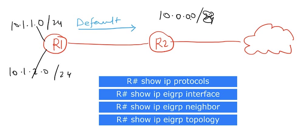
After receiving the message of the first router, R2 puts in its routing table a record that the route to the network 10.0.0.0/8 is carried out through R1. Suppose that traffic for the 10.1.3.0/24 network arrives at the second router. Guided by this entry, R2 will forward this traffic to R1.
Having received traffic for the 10.1.3.0 network, R1 router will not find it in its routing table, but since it has a default route to R2, where it should address all unknown traffic, it will send the received message back to R2 router. R2 will send it to R1 again, and we will get a traffic loop that will continue until the TTL packet lifetime counter reaches 0.

The routing loop created by summing the routes is a problem that any router in auto-summing mode uses Null0 to solve. So if Null0 is present in the routing table, this serves as evidence of automatic or manual route summation.
This way, I understand that R1 uses route summarization because it uses the Null0 pseudo-interface, which does not accept or redirect traffic to prevent looping. It acts like a "black hole" in which the traffic addressed to all addresses of the 10.0.0.0/8 block disappears, except for the addresses of specific subnets mentioned in the routing table. In our case, these are networks 10.1.10.0/24 and 10.1.10.1/32. At the same time, traffic for these subnets will go through the corresponding interfaces, and traffic for the remaining addresses of block 10.0.0.0/8 will go to Null0.
Simply put, if for some network there is no special route in the routing table, packets addressed to it are sent to the dump, to the “black hole” Null0, which acts as a “killer” of traffic. This is how the mechanism of preventing traffic looping in dynamic routing protocols works.
At present, I cannot say that the summation of routes is the reason that computers cannot ping each other, but we must bear in mind that we have some kind of summation here.
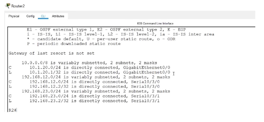
I did not see that we have a neighborhood, since the table does not have routes to neighboring devices. Let's go into the R2 settings and enter the show ip route command. We see that R2 does not perform route summation. Because the table does not have the Null0 interface.
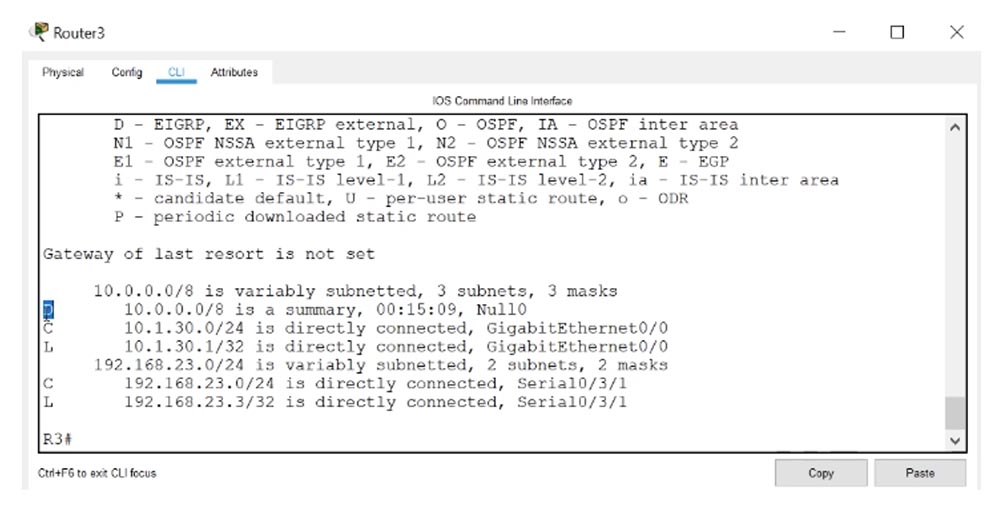
I use the same command for R3 and see that some type of summation is also used here, since Null0 is present in the table.
Since the connections between the networks of three offices are displayed in red on the circuit diagram, we can conclude that there are problems. If you use the show ip eigrp interfaces command to ask R3 to show the status of the interfaces using EIGRP protocol, it will display the GigabitEthernet0 / 0 interface and the serial interface Se0 / 3/0 to which the R2 router is connected.

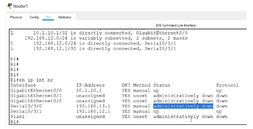
I enter the show ip interface brief command, and we see that Se0 / 3/0 is turned off and is in the down state, and there are no problems with the PC3 connecting to this router.
Now I will enter the same command in the settings of the R1 router - there is a similar situation here, that is, the Se0 / 3/0 interface connecting R1 and R3 is also disabled. Perhaps this is the reason for the impossibility of pinging computers.
We will try to solve this problem. Technically, according to our topology, neighbor relations should form between the routers R1 and R3.

This did not happen, because at the logical level, the routers are not connected, since the corresponding serial interfaces are in an administratively down state. It may be that someone mistakenly used the shutdown command or something like this, but we should not care about the cause of this problem, we just need to fix it. Therefore, in the settings of the R1 router, I sequentially enter the commands config t (erminal), int (erface) se0 / 3/0 and no shut (down). I turned on this interface, and now the system begins to configure it. We see that everything went fine - we have a record that a new neighborhood has been established with the device 192.168.13.3. Next, I enter the show ip eigrp interfaces command, and make sure that all 3 interfaces are now enabled on R1.
The show ip eigrp neighbors command shows that the se0 / 3/0 interface to which the 192.168.13.3 network is connected is connected to a neighbor.

Why didn’t the neighborhood between the routers R1 and R2 be established? We see that EIGRP is launched on all R1 interfaces, including on the Se0 / 3/1 interface, to which R2 is connected, but the R1 router does not see its neighbor. Let's use the show ip protocols test command, which will show all network protocols running on this device. I enter the same command in the R2 console, and now we are able to compare information in both settings windows.

In the first case, eigrp-1 and AS1 work, in the second - eigrp-10 and AS10. We know that in order to establish a neighborhood, ASs must match, so the cause of the problem lies precisely in this. The second reason for the impossibility of establishing a neighborhood may be different values of the coefficients of the metric K, but in our country they coincide. In the CCNA course, you do not have to solve problems on the subject of these coefficients, just keep in mind that they must coincide, otherwise it will not be possible to establish a neighborhood between routers.
Similarly, the device passwords must match if the authentication setting was used. Authentication is also not part of your CCNA course, so just remember this rule.
We see one more difference: R1 router uses automatic route summation, while R2 has this feature disabled. Perhaps, to some extent, this can create problems, but in this case, the summation does not affect the establishment of neighborly relations.
I think that in the parameters of the R3 router, eigrp-1 will also be present, since they established a neighborhood. Since the cause of the problem is the eigrp-10 of the R2 router, let's try changing this setting to eigrp-1. To do this, I enter the show run | command in the R2 console begin eigrp and copy the parameters of the network routes Routing for Networks.
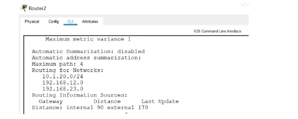
Next, I enter global configuration mode, enter the no router eigrp 10 command, and then use the router eigrp 1 command. After it, I paste the 3 lines of Routing for Networks parameters copied above. As you can see, we immediately established neighborly relations with the device 192.168.23.3, which is connected to the Serial0 / 3/1 interface.
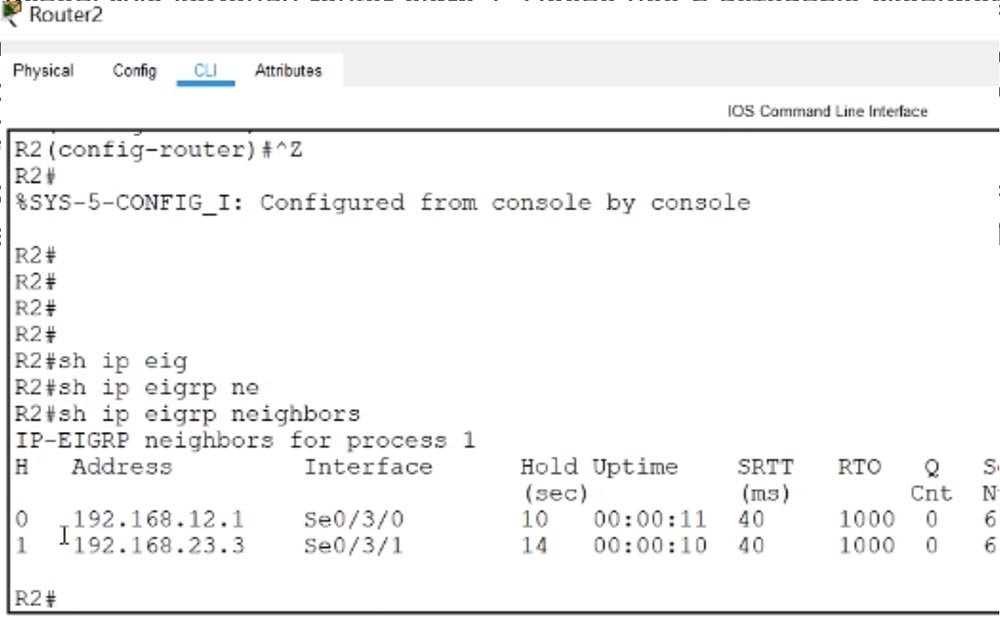
I enter the show ip eigrp neighbors command and see that now R2 has two neighbors - this is R1 router with address 192.168.12.1 and R3 router with address 192.168.23.3.
After entering a similar command in the R1 console, I see that he also has a new neighbor - the R2 router, connected to the Sw0 / 3/1 serial interface.

Let's see what happened now that these routers have established a neighborhood.
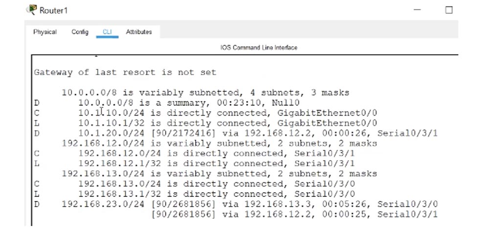
The show ip route command shows that the 10.1.10.0/24 and 10.1.20.0/24 networks are connected to the R1 router, but where is the 10.1.30.0/24 network? A similar situation is observed with R2 router - it sees only the 10.1.20.0/24 network, that is, itself, "not noticing" the tenth and thirtieth network. The reason is that auto-summing of routes created a problem for us.
In the R2 console, you can see that as a result of auto-summing through the interfaces 192.168.12.1. and 192.168.23.3 load balancing for the network 10.0.0.0/8.
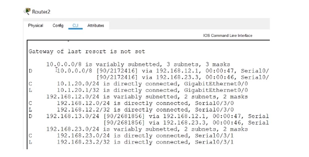
Autosumming takes place on the R1-R2 section, this is the subnet 192.168.12.1, and on the R2-R3 section, this is the 192.168.23.3 subnet.

In load balancing mode, very interesting things happen. Let's go to the PC2 command line terminal and enter the ping 10.1.10.10 command, that is, we will ping the PC1 computer. We see that at first we receive a response from 10.1.10.1, followed by a message that the host at 192.168.23.3 is unavailable.

This shows how load balancing works: the R2 router sends one ping packet on the R2-R1 channel, the second packet on the R1-R3 channel, and so on. The router R1 receives the request and sends a response, and the router R3, having received the packet addressed to 10.1.10.10, has no idea what the destination is, because it is not in the routing table.
I go into R3 settings and enter the show ip route command. We see that the router does not know anything about 10.1.10.10, but it uses the total route 10.0.0.0/8 with the Null0 interface.

Thus, all traffic addressed to the device, whose address is present in the address block 10.0.0.0/8, but whose route is not described in the routing table, is sent to the Null0 “dump” to prevent looping.
A similar situation occurs when ping a PC3 computer at 10.1.30.30 - communication with it is established, and ping through the interface 192.168.12.1, that is, the packet to PC1 does not pass with the message “destination host is not available”.

So, we were convinced that the auto-summing of the routes really created problems for us. Therefore, let's go back to the settings of R1 and cancel all auto-summation. To do this, I type the commands config t, router eigrp 1 and no auto-summary. I do the same for the R3 router.
Let's see what came of it. We go to the PC2 command line terminal and enter the ping 10.1.10.10 command. As you can see, the ping of PC1 was successful. Similarly, we easily ping the PC3 computer at 10.1.30.30.
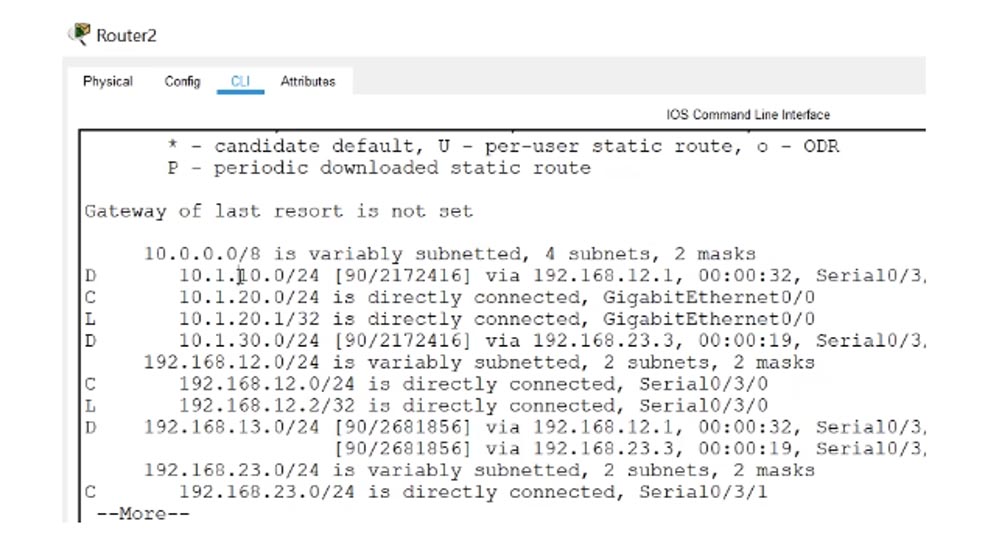
We go into the R2 console and enter the show ip route command. We see that now in the routing table entries for routes for all subnets 10.1.10.0/24, 10.1.20.0/24 and 10.1.30.0/24, announced by the EIGRP protocol, appeared. Now the router knows how to contact all subnets.
Now all devices should ping each other without problems. We see that PC3 successfully pings PC2 at 10.1.20.20 and PC1 at 10.1.10.10. The situation is similar with PC1 when ping PC2 and PC3. As you can see, everything is very simple. Let's go back to the slide with test commands that should be used to troubleshoot EIGRP configuration.

The first thing you should do when troubleshooting is to check the physical state of the connections to make sure that all switches and routers are turned on and in working condition. If this does not solve the problem, use the show ip protocols command. This will help you determine which protocols are running on the device and what are the settings for their settings. This team helped us to detect the discrepancy between eigrp 1 and eigrp 10 and fix this problem. Next, you need to consistently use the show ip eigrp interface, show ip eigrp neighbor and commands to view the interface table, neighbor table, and topology table.
The show ip eigrp interface command will give you the opportunity to see which interfaces work, let's check this with the example of R1 router. You see that two serial interfaces have neighbors.

The show ip eigrp neighbor command will let us see what these neighbors are.

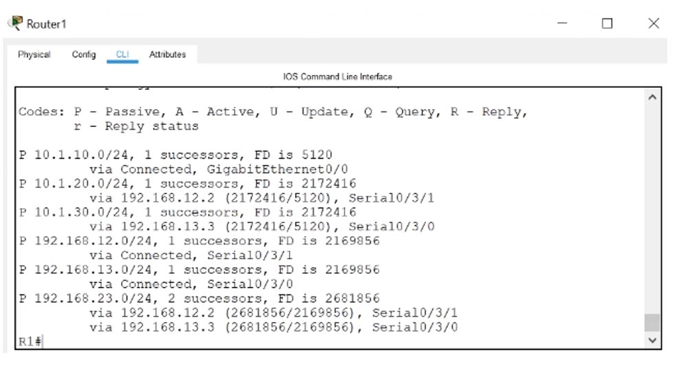
The show ip eigrp topology command will provide FD information and other topology parameters for the entire network.
Remember that before using these commands it is advisable to check the physical state of network devices, and do not forget that the Null0 interface serves to prevent traffic from looping when adding routes. Autosumming in itself does not create problems, but you should know that in some cases it is capable of it.
Thank you for staying with us. Do you like our articles? Want to see more interesting materials? Support us by placing an order or recommending it to your friends, a 30% discount for Habr users on a unique analogue of entry-level servers that was invented by us for you: The whole truth about VPS (KVM) E5-2650 v4 (6 Cores) 10GB DDR4 240GB SSD 1Gbps from $ 20 or how to divide the server? (options are available with RAID1 and RAID10, up to 24 cores and up to 40GB DDR4).
Dell R730xd 2 times cheaper? Only we have 2 x Intel TetraDeca-Core Xeon 2x E5-2697v3 2.6GHz 14C 64GB DDR4 4x960GB SSD 1Gbps 100 TV from $ 199 in the Netherlands! Dell R420 - 2x E5-2430 2.2Ghz 6C 128GB DDR3 2x960GB SSD 1Gbps 100TB - from $ 99! Read about How to Build Infrastructure Bldg. class c using Dell R730xd E5-2650 v4 servers costing 9,000 euros for a penny?
We are still continuing the topic of section 2.6 of the ICND2 course, and as I said, you should go to the site and download the lab “Day 51: EIGRP Troubleshooting,” which is an archived file for the Cisco Packet Tracer program.
I have already completed the initial settings in this lab so that we can consider troubleshooting the most common protocol configuration problems 3 months ago. Since then, I have not had time to finish this video tutorial, so I forgot about what kind of problems we are talking about.
The purpose of this lab is to make sure that three computers, PC1, PC2, and PC3 can ping each other. Let's see if this is possible right now. I go to the PC1 command line terminal and enter the command to ping PC2: ping 10.1.20.20, after which I get a system notification that the destination host is unavailable. The situation is similar with the ping of PC3 at 10.1.30.30.
Now I will try to ping other computers from PC2. PC1 at 10.1.10.10 is unavailable in the same way as PC3. This means that in the routing table of router R2, the required entry is missing.
Let's try to start ping from PC3. As you can see, PC1 and PC2 are also unavailable.
Let's see why we are unable to establish a connection between computers. We have 3 offices: in Bangalore, Boston and Paris, whose networks are connected to each other using the EIGRP protocol. Let's start with troubleshooting the R1 router. I go to the CLI console and am going to enter the show ip eigrp command, but first I want to make sure that EIGRP is configured on this device. To do this, I use the show run | begin eigrp. As you can see, the protocol works.
In order to make sure that the EIGRP protocol is running on all 3 routers, I carry out a similar check for R2 and R3. The protocol works, but ping does not pass.
I go into the R1 settings and enter the show ip route command. We see that thanks to EIFRP, the router “learned” some routes, but these are summarized routes marked Null0.
If you remember, when auto-summing routes, the router starts to summarize all the routes according to the settings of this function. In this case, he summed up the whole 10.0.0.0/8 network block, including the routes of many subnets, which are not really parts of the 10.0.0.0 network.
Almost all network protocols use the Null0 concept to prevent traffic loops. So that you understand this concept, I will give one example. Suppose we have an R1 router, an R2 router, and the Internet. Between R1 and R2 there is a default route Default route. This means that if the first router does not know a specific route, it sends all traffic along the default route to R2, because it is connected to an external network.
Suppose that R1 performs the summation of routes, while 2 networks are connected to it: 10.1.1.0/24 and 10.1.2.0/24. As a result, it sends the total route 10.0.0.0/8 to R2.
After receiving the message of the first router, R2 puts in its routing table a record that the route to the network 10.0.0.0/8 is carried out through R1. Suppose that traffic for the 10.1.3.0/24 network arrives at the second router. Guided by this entry, R2 will forward this traffic to R1.
Having received traffic for the 10.1.3.0 network, R1 router will not find it in its routing table, but since it has a default route to R2, where it should address all unknown traffic, it will send the received message back to R2 router. R2 will send it to R1 again, and we will get a traffic loop that will continue until the TTL packet lifetime counter reaches 0.
The routing loop created by summing the routes is a problem that any router in auto-summing mode uses Null0 to solve. So if Null0 is present in the routing table, this serves as evidence of automatic or manual route summation.
This way, I understand that R1 uses route summarization because it uses the Null0 pseudo-interface, which does not accept or redirect traffic to prevent looping. It acts like a "black hole" in which the traffic addressed to all addresses of the 10.0.0.0/8 block disappears, except for the addresses of specific subnets mentioned in the routing table. In our case, these are networks 10.1.10.0/24 and 10.1.10.1/32. At the same time, traffic for these subnets will go through the corresponding interfaces, and traffic for the remaining addresses of block 10.0.0.0/8 will go to Null0.
Simply put, if for some network there is no special route in the routing table, packets addressed to it are sent to the dump, to the “black hole” Null0, which acts as a “killer” of traffic. This is how the mechanism of preventing traffic looping in dynamic routing protocols works.
At present, I cannot say that the summation of routes is the reason that computers cannot ping each other, but we must bear in mind that we have some kind of summation here.
I did not see that we have a neighborhood, since the table does not have routes to neighboring devices. Let's go into the R2 settings and enter the show ip route command. We see that R2 does not perform route summation. Because the table does not have the Null0 interface.
I use the same command for R3 and see that some type of summation is also used here, since Null0 is present in the table.
Since the connections between the networks of three offices are displayed in red on the circuit diagram, we can conclude that there are problems. If you use the show ip eigrp interfaces command to ask R3 to show the status of the interfaces using EIGRP protocol, it will display the GigabitEthernet0 / 0 interface and the serial interface Se0 / 3/0 to which the R2 router is connected.
I enter the show ip interface brief command, and we see that Se0 / 3/0 is turned off and is in the down state, and there are no problems with the PC3 connecting to this router.
Now I will enter the same command in the settings of the R1 router - there is a similar situation here, that is, the Se0 / 3/0 interface connecting R1 and R3 is also disabled. Perhaps this is the reason for the impossibility of pinging computers.
We will try to solve this problem. Technically, according to our topology, neighbor relations should form between the routers R1 and R3.
This did not happen, because at the logical level, the routers are not connected, since the corresponding serial interfaces are in an administratively down state. It may be that someone mistakenly used the shutdown command or something like this, but we should not care about the cause of this problem, we just need to fix it. Therefore, in the settings of the R1 router, I sequentially enter the commands config t (erminal), int (erface) se0 / 3/0 and no shut (down). I turned on this interface, and now the system begins to configure it. We see that everything went fine - we have a record that a new neighborhood has been established with the device 192.168.13.3. Next, I enter the show ip eigrp interfaces command, and make sure that all 3 interfaces are now enabled on R1.
The show ip eigrp neighbors command shows that the se0 / 3/0 interface to which the 192.168.13.3 network is connected is connected to a neighbor.
Why didn’t the neighborhood between the routers R1 and R2 be established? We see that EIGRP is launched on all R1 interfaces, including on the Se0 / 3/1 interface, to which R2 is connected, but the R1 router does not see its neighbor. Let's use the show ip protocols test command, which will show all network protocols running on this device. I enter the same command in the R2 console, and now we are able to compare information in both settings windows.
In the first case, eigrp-1 and AS1 work, in the second - eigrp-10 and AS10. We know that in order to establish a neighborhood, ASs must match, so the cause of the problem lies precisely in this. The second reason for the impossibility of establishing a neighborhood may be different values of the coefficients of the metric K, but in our country they coincide. In the CCNA course, you do not have to solve problems on the subject of these coefficients, just keep in mind that they must coincide, otherwise it will not be possible to establish a neighborhood between routers.
Similarly, the device passwords must match if the authentication setting was used. Authentication is also not part of your CCNA course, so just remember this rule.
We see one more difference: R1 router uses automatic route summation, while R2 has this feature disabled. Perhaps, to some extent, this can create problems, but in this case, the summation does not affect the establishment of neighborly relations.
I think that in the parameters of the R3 router, eigrp-1 will also be present, since they established a neighborhood. Since the cause of the problem is the eigrp-10 of the R2 router, let's try changing this setting to eigrp-1. To do this, I enter the show run | command in the R2 console begin eigrp and copy the parameters of the network routes Routing for Networks.
Next, I enter global configuration mode, enter the no router eigrp 10 command, and then use the router eigrp 1 command. After it, I paste the 3 lines of Routing for Networks parameters copied above. As you can see, we immediately established neighborly relations with the device 192.168.23.3, which is connected to the Serial0 / 3/1 interface.
I enter the show ip eigrp neighbors command and see that now R2 has two neighbors - this is R1 router with address 192.168.12.1 and R3 router with address 192.168.23.3.
After entering a similar command in the R1 console, I see that he also has a new neighbor - the R2 router, connected to the Sw0 / 3/1 serial interface.
Let's see what happened now that these routers have established a neighborhood.
The show ip route command shows that the 10.1.10.0/24 and 10.1.20.0/24 networks are connected to the R1 router, but where is the 10.1.30.0/24 network? A similar situation is observed with R2 router - it sees only the 10.1.20.0/24 network, that is, itself, "not noticing" the tenth and thirtieth network. The reason is that auto-summing of routes created a problem for us.
In the R2 console, you can see that as a result of auto-summing through the interfaces 192.168.12.1. and 192.168.23.3 load balancing for the network 10.0.0.0/8.
Autosumming takes place on the R1-R2 section, this is the subnet 192.168.12.1, and on the R2-R3 section, this is the 192.168.23.3 subnet.
In load balancing mode, very interesting things happen. Let's go to the PC2 command line terminal and enter the ping 10.1.10.10 command, that is, we will ping the PC1 computer. We see that at first we receive a response from 10.1.10.1, followed by a message that the host at 192.168.23.3 is unavailable.
This shows how load balancing works: the R2 router sends one ping packet on the R2-R1 channel, the second packet on the R1-R3 channel, and so on. The router R1 receives the request and sends a response, and the router R3, having received the packet addressed to 10.1.10.10, has no idea what the destination is, because it is not in the routing table.
I go into R3 settings and enter the show ip route command. We see that the router does not know anything about 10.1.10.10, but it uses the total route 10.0.0.0/8 with the Null0 interface.
Thus, all traffic addressed to the device, whose address is present in the address block 10.0.0.0/8, but whose route is not described in the routing table, is sent to the Null0 “dump” to prevent looping.
A similar situation occurs when ping a PC3 computer at 10.1.30.30 - communication with it is established, and ping through the interface 192.168.12.1, that is, the packet to PC1 does not pass with the message “destination host is not available”.
So, we were convinced that the auto-summing of the routes really created problems for us. Therefore, let's go back to the settings of R1 and cancel all auto-summation. To do this, I type the commands config t, router eigrp 1 and no auto-summary. I do the same for the R3 router.
Let's see what came of it. We go to the PC2 command line terminal and enter the ping 10.1.10.10 command. As you can see, the ping of PC1 was successful. Similarly, we easily ping the PC3 computer at 10.1.30.30.
We go into the R2 console and enter the show ip route command. We see that now in the routing table entries for routes for all subnets 10.1.10.0/24, 10.1.20.0/24 and 10.1.30.0/24, announced by the EIGRP protocol, appeared. Now the router knows how to contact all subnets.
Now all devices should ping each other without problems. We see that PC3 successfully pings PC2 at 10.1.20.20 and PC1 at 10.1.10.10. The situation is similar with PC1 when ping PC2 and PC3. As you can see, everything is very simple. Let's go back to the slide with test commands that should be used to troubleshoot EIGRP configuration.
The first thing you should do when troubleshooting is to check the physical state of the connections to make sure that all switches and routers are turned on and in working condition. If this does not solve the problem, use the show ip protocols command. This will help you determine which protocols are running on the device and what are the settings for their settings. This team helped us to detect the discrepancy between eigrp 1 and eigrp 10 and fix this problem. Next, you need to consistently use the show ip eigrp interface, show ip eigrp neighbor and commands to view the interface table, neighbor table, and topology table.
The show ip eigrp interface command will give you the opportunity to see which interfaces work, let's check this with the example of R1 router. You see that two serial interfaces have neighbors.
The show ip eigrp neighbor command will let us see what these neighbors are.
The show ip eigrp topology command will provide FD information and other topology parameters for the entire network.
Remember that before using these commands it is advisable to check the physical state of network devices, and do not forget that the Null0 interface serves to prevent traffic from looping when adding routes. Autosumming in itself does not create problems, but you should know that in some cases it is capable of it.
Thank you for staying with us. Do you like our articles? Want to see more interesting materials? Support us by placing an order or recommending it to your friends, a 30% discount for Habr users on a unique analogue of entry-level servers that was invented by us for you: The whole truth about VPS (KVM) E5-2650 v4 (6 Cores) 10GB DDR4 240GB SSD 1Gbps from $ 20 or how to divide the server? (options are available with RAID1 and RAID10, up to 24 cores and up to 40GB DDR4).
Dell R730xd 2 times cheaper? Only we have 2 x Intel TetraDeca-Core Xeon 2x E5-2697v3 2.6GHz 14C 64GB DDR4 4x960GB SSD 1Gbps 100 TV from $ 199 in the Netherlands! Dell R420 - 2x E5-2430 2.2Ghz 6C 128GB DDR3 2x960GB SSD 1Gbps 100TB - from $ 99! Read about How to Build Infrastructure Bldg. class c using Dell R730xd E5-2650 v4 servers costing 9,000 euros for a penny?
All Articles