Battery Power for MySensors Devices
This music will last forever if I replace the batteries (C)

This opus is dedicated to my research on the power of autonomous wireless devices that are part of the MySensors smart home system.
First there was lithium ...
Rather, lithium-ion and lithium-polymer batteries.
For a long time, these batteries from old gadgets accumulated in a box. I thought - here it is, universal power for all small-sized microcontrollers. Moreover, the voltage of 3.3-4.2V is perfect for both AVR, and for all kinds of ESP and STM. For reliability, you can put an LDO stabilizer of the required power and get a stable 3.3 for MK and the entire periphery.

But as it turned out, not everything is so good.
- Batteries needed to be charged. To do this, it was necessary to make them removable, or add a charging module to your device, which, in turn, gave additional cost, dimensions and charging holes in the case. And it’s not always convenient to charge devices, for example, a weather sensor outside the window.
- Lithium batteries (like most power supplies in general) are not suitable for use at low temperatures. In a weather sensor attached to the window, in winter, the battery sank immediately in the cold.
- During long-term operation, if the battery voltage is not monitored in time, you can discharge it "to zero", that is, below the permissible value, which is guaranteed to kill it. So you need protection against overdischarge.
- A variety of battery sizes and capacities significantly limited the repeatability of devices in identical enclosures. And the reserves of old batteries quickly came to an end - as a result, it was necessary to buy somewhere new. And, as it turned out, the cost of such power sources turned out to be quite cheap and added at least $ 2 to the cost of each device (and taking into account the charging board and more). Moreover, there was no economy from rechargeability, since most autonomous controllers consumed very little energy and could work for months without recharging.
NiMH and other AA / AAA batteries were even worse. They needed to be charged in a special charger, they had a “memory effect” and an initially low voltage (1.2-1.3V), and when connected in series due to the difference in internal resistance, one of the batteries could be discharged more than others, which again led to its spoilage.
And again, lithium ...
Now there are round small 3.0V lithium batteries, in favor of which I decided to abandon capricious and expensive batteries.
CR2032 batteries are used in a huge number of BIOS computers, electric meters and other devices with RTC, watches, calculators and various toys. With small dimensions and low price, they have a voltage of 3.0V, which is quite sufficient for the MK and a decent capacity of 200-250mA / h for their dimensions.

But again, problems. The fact of the matter. that the direct current of such a battery is only 0.4mA. If you load it with a higher current, the battery voltage will drop, although then it can partially or completely recover. A typical Mysensor sleep mode consumes several microamps. But in the transfer mode, it’s already about 15-20mA. At the same time, new versions of the MySensors library make devices send a lot of packets - ping, greeting, presentations, searching for a gateway or router, which results in a long, sometimes several seconds, operation of the radio module. At a voltage of about 2V, cheap Chinese NRF24L01 start to fail, and sometimes it’s not even possible to get them into sleep () sleep mode from MySensors.
As a result, everything works somehow on a fresh battery, but as the battery discharges, communication problems increase, the radio module starts to flood more on the air, increasing the battery discharge. In the end, the voltage drops to the point that the entire device stops going to sleep mode, and then a cyclic reboot occurs until the battery runs out completely.
Depending on the manufacturer and the "freshness" of the battery, the device can work from a couple of days to a month. If you buy cheap batteries on aliexpress, then there’s a lottery. The transition to the more capacious CR2450 and CR2477 saves a little, but they do not know how to give a current of more than 0.5mA for a long time.
For a while I experimented with boost converters that allowed the battery to maintain normal operating voltage for the MK until the last crumbs of energy, but they had a small, but non-zero quiescent current, which reduced the overall service life.
Little fingers - little fingers

It’s time to calm down and adopt the “advanced” Chinese experience, to power all of your devices from three AAA (batteries are not included). But I decided to look for a solution with at least two 1.5 volt batteries.
I stopped at such a scheme with a boost stabilizer NCP1400 :
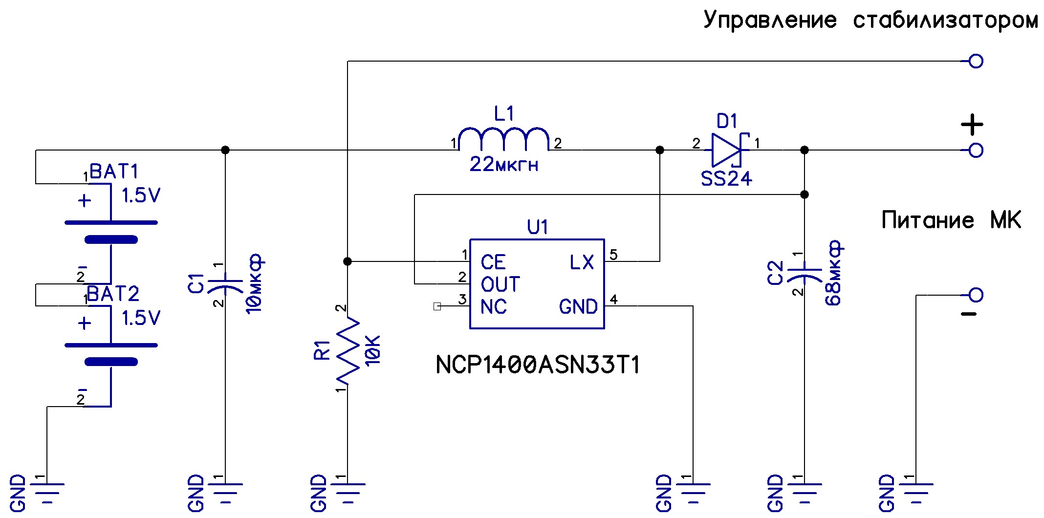
Two series-connected AAA alkaline batteries initially give 2.7-3.1V by the end of the production period, reducing the voltage to 1-2V
When the NCP1400 is off (low level at the control input), the battery power immediately goes to the MC through the L1 coil and the Schottky diode D1 with a minimum voltage drop of about 0.1V. If a high level is applied to the control input, the NCP1400 stabilizer starts up and gives 3.3V voltage to the MK with a total battery voltage of 0.8V to 3.1V.
The operation algorithm is as follows:
- The main time the controller is in PowerDownMode, all peripherals, including the NRF24 are disabled or also in low power mode.
- The MC leaves sleep mode by interruption from the timer or by an external interruption (for example, in switches by interruption from the button), the supply voltage VCC (built-in function of the AVR controllers) is measured.
- If the supply voltage is greater than 3V (or other voltage sufficient for stable peripheral operation), then the NCP1400 does not start and all processing is carried out at this supply voltage until the next sleep cycle.
- If the voltage is lower than 3V, the NCP1400 stabilizer starts, the supply voltage is set to 3.3V, all regular processing of the device is performed, including sending data via NRF24
- Further, if the voltage is above 1.7V (sufficient voltage to exit the MC from sleep mode), then the NCP1400 turns off until the next wake-up cycle.
- If the voltage is less than 1.7 (the minimum voltage of the MK), then the NCP1400 does not turn off until the controller reboots or until the supply voltage drops below 0.8V (voltage of the NCP1400)
#define MY_RF24_CE_PIN 9 #define MY_RF24_CS_PIN 10 #define MY_RF24_POWER_PIN 8 #define MY_RADIO_NRF24 #include <MySensors.h> #define PIN_NCP1400 2 #define CHILD_ID_VCC 0 MyMessage msgVcc(CHILD_ID_VCC, V_VOLTAGE); bool low_power = false; int readVcc(); // void before(){ pinMode(PIN_NCP1400,OUTPUT); digitalWrite(PIN_NCP1400,HIGH); } void presentation(){ sendSketchInfo("NCP1400 test", "1.0"); present(CHILD_ID_VCC, S_MULTIMETER,"mV"); } // void loop(){ int vcc = 1000; if( low_power == false ){ vcc = readVcc(); digitalWrite(PIN_NCP1400,HIGH); // NRF1400 } if( vcc < 1700 )low_power = true; // NRF1400 send(msgVcc.set(vcc)); // VCC if( low_power == false )digitalWrite(PIN_NCP1400,LOW); // NRF1400 sleep( 300000 ); // 5 } /** * VCC */ int readVcc() { long result; // Read 1.1V reference against AVcc ADMUX = _BV(REFS0) | _BV(MUX3) | _BV(MUX2) | _BV(MUX1); delay(2); // Wait for Vref to settle ADCSRA |= _BV(ADSC); // Convert while (bit_is_set(ADCSRA,ADSC)); result = ADCL; result |= ADCH<<8; result = (1100L * 1023)/result; return((int)result); }
Testing
And how do we deal with current consumption in practice? I connect my circuit to the LBP and take measurements of the current consumption and output voltage.
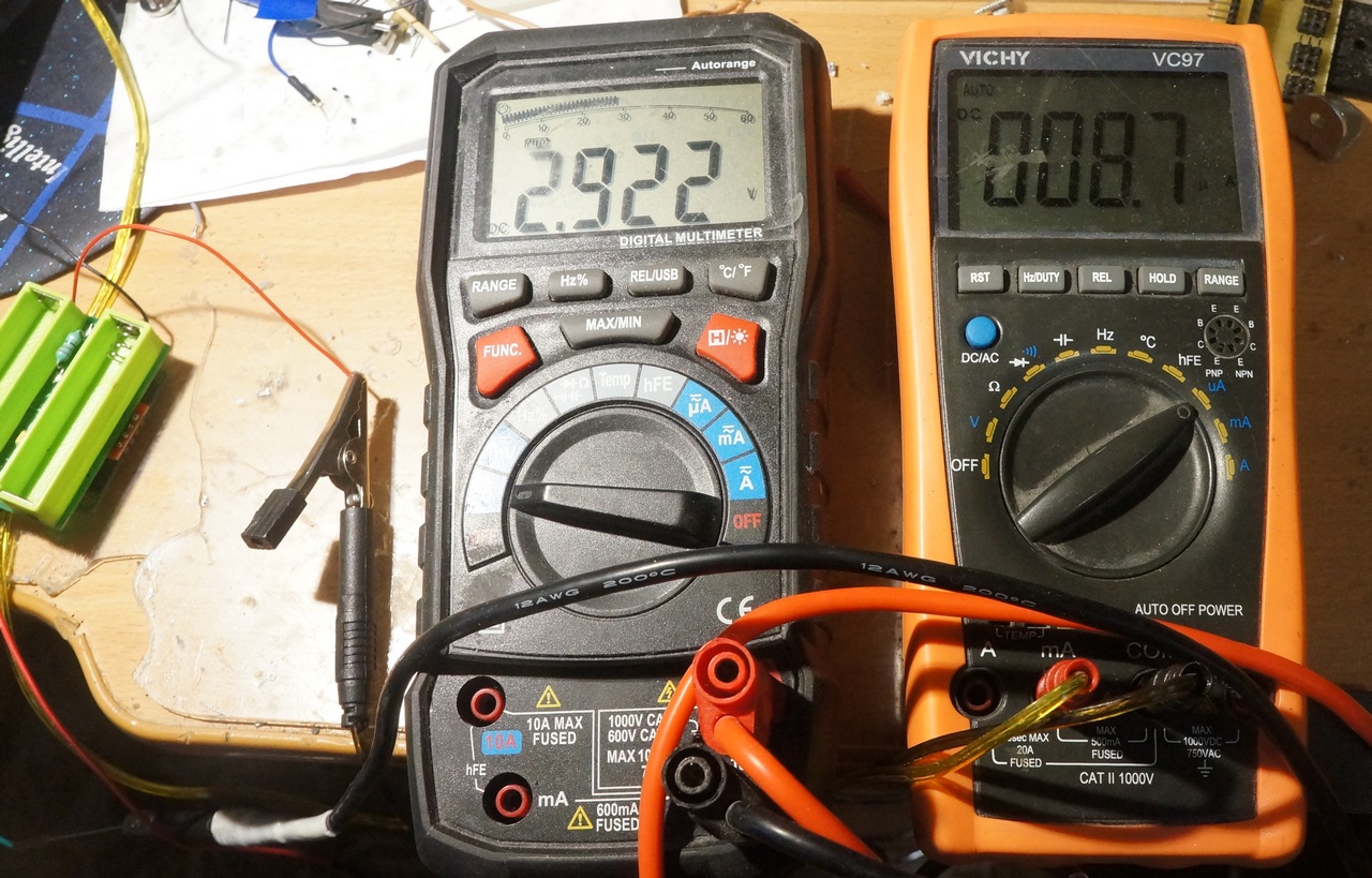
Idling current with the NCP1400 turned off and an input voltage of 1-3 V was 0.3 μA. Even lower than the declared by datasheet 0.5mkA (or maybe on this range my devices give a large error). But with the stabilizer turned on without load, the current turned out to be unexpectedly large - more than 0.3mA. It turned out that the pull-up resistor R1 caused a large consumption. Replacing the R1 rating from 10K to 150K, I got 30 μA at an input voltage of 3.0 V and 44 μA at 1.0 V.
If you completely remove the resistor R1, then the stabilizer in the absence of connecting this input to the MC will be constantly on consuming with an input 2V of the order of 11 μA.
Now I connect the microcontroller with NRF24L01 and the HUD21 sensor, working according to the above described algorithm:
- Input voltage 3.0V - active mode (NCP1400 is on) 32mA, sleep mode (NCP1400 is off) 9uA
- Input voltage 2.0V - active mode (NCP1400 on) 51mA, sleep mode (NCP1400 off) 6mA
- Input voltage 1.7V - active mode (NCP1400 on) 63mA, sleep mode (NCP1400 off) 5.6mA
- Input voltage 1.0V - NCP1400 is constantly on - sleep mode 197mkA
- Input voltage 0.5V - NCP1400 is constantly on - 397μA sleep mode
Active battery consumption increases when power is reduced. The voltage of 1.7V was selected experimentally. Below this value, the microcontroller may already stably not work. When the battery voltage drops below this threshold, the NCP1400 stabilizer no longer turns off and consumption in sleep mode is quite high. In this mode, the batteries will not last long, but there will be enough time to replace them.
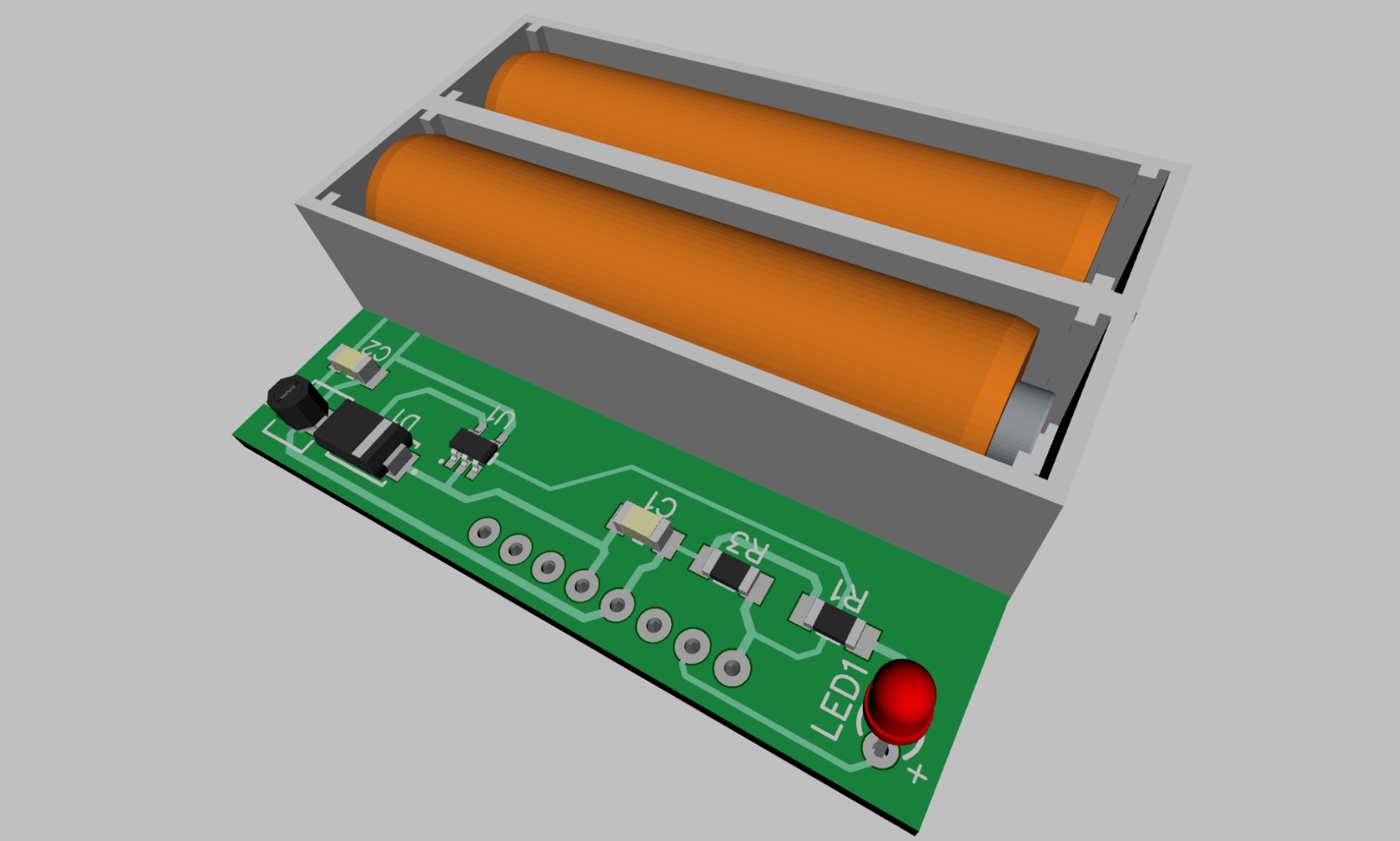
Embodiment in the gland
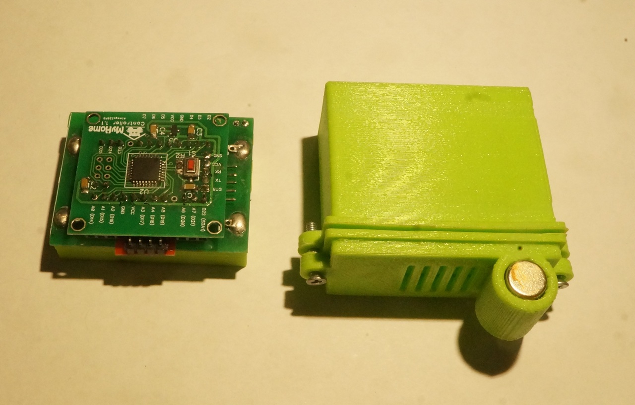
Designed universal power boards for my smart home devices

And although the finished devices were not as compact as with lithium batteries, the result was quite fine with me. especially considering the cost of alkaline batteries in the stores of Galomart, Kastorama, Leroyle, etc.
Currently, I operate at home more than a dozen different devices for monitoring temperature, soil moisture, etc. in the MuSensors / MajorDoMo system.
Read more on my blog
All Articles