Smart antenna for LTE networks
Currently, many people use the Internet LTE. However, if in large cities there are no problems with network coverage and Internet speed, in the suburbs, subscribers face the problem of poor reception. The reason for this is not only the weak signal itself, but also the occurrence of multiple signal reflections along the path from the base station (BS) to the subscriber. This article describes the development of a smart antenna that adapts to the conditions of signal reception.
On the Internet, there are many offers to sell external antennas for connecting to 4G modems. And although mobile operators do not recommend this, and even threaten to remove the modem from the guarantee, since the connectors on the modems are considered exclusively service, external antennas are sold very well. Several years ago, when the first Wimax modems from Yota, which were produced by Samsung, appeared, the coverage of that network was not very good even in the city. At the same time, the first external antennas of Chinese and one Russian manufacturer, Resonance, appeared on the market. The Wimax standard has now changed LTE, and all mobile operators sell portable modems. The market of external antennas has expanded significantly, you can find dozens of different types on the Internet. Some companies offer turnkey installation and creation of complete systems for country houses, using active amplifiers and additional antennas installed inside the house for local distribution of the signal. But for communication with the base station, in the overwhelming majority of cases, highly directional antennas are used, most often printed antenna arrays having a beam width of about 20 degrees both in azimuth and in elevation. The main problem of directional antennas is that they are manually sent once to a specific BS and, in the event of a signal loss from this BS, the connection is interrupted. The solution to this problem is smart antennas, which themselves are tuned to the base station without any human intervention. Most often they are used for installation on automobiles and other mobile objects (not in Russia) or for creating temporary communication channels where necessary and there are no other ways to quickly establish communication.
Smart antennas are of two types: adaptive and switching. An adaptive antenna is, in fact, an antenna array with the ability to instantly synthesize rays in arbitrary directions. The switched antenna has several antennas in different directions (usually in a circle), and, depending on which direction the signal is stronger, one or another antenna turns on, the remaining antenna antennas are inactive and wait for either a change in the subscriber’s position or switch to another base station, if the signal from for some reason became stronger. Thus, a smart antenna differs from known systems in that it adapts to changing reception conditions. Often the signal from different base stations may differ depending on the time of day or the time of year. And yet, thanks to this advantage, such an antenna can be used, for example, on hikes or in motor homes.
In order to test how such an antenna will work in real conditions, the team of authors has developed the simplest and cheapest smart antenna and conducted field tests.
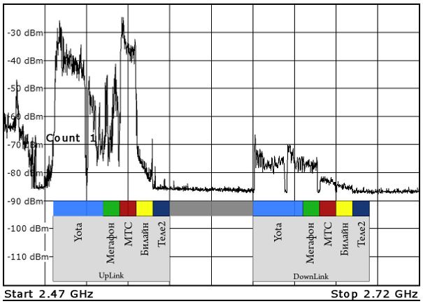
It is known that the frequency range allocated for LTE is 200 MHz - 2.5 to 2.7 GHz. To clearly see this, an omnidirectional antenna was connected to the spectrum analyzer, the analyzer itself was switched to accumulation mode and left for a sufficiently long time. The results are shown in the graph above. In the same place, the subbands of various operators are plotted on the chart (information about the frequencies of the operators is found on the Internet). No further comments are required, except that the top Wi-Fi channels are also captured on the chart.
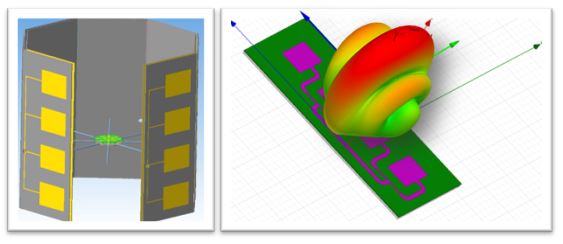
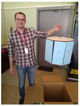
The proposed design is a drum of 8 faces and includes a microwave switch and control board. Each face is a separate antenna, which is a 4x1 printed grid. So that the rays do not overlap, but there are no “blind” zones, the azimuth width of the beam is 65 degrees and 19 degrees in elevation to achieve high gain (approximately 12 dBi). For ease of fabrication, a porous, but rather rigid insulation 5 mm thick was used as a substrate for microstrip patches. The dielectric constant of such a material is close to unity, and the insertion loss is negligible, which was tested on a specially made single patch. The strip lines, as well as the screens of the antennas, were cut out of copper foil deposited on thin lavsan, and glued with adhesive tape to the substrate. The antennas were designed for a frequency of 2.6 GHz, the CWS at the center frequency turned out to be close to 1, at the edges of the range it rose to 2, which is quite acceptable for antennas of communication devices.
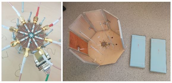
Separately, an eight-channel switch was made, which connects the modem input to one of eight antennas aimed at the BS with the best signal. As controllable elements, pin-diodes from Infineon were used, and according to the authors, the control board should control them, which, receiving information from the modem, chooses which side is the best and that channel includes. Such a survey (verification of signals from all antennas) should occur several times per minute. Thus, when there is a change in the interference environment or signal strength from the BS, the smart antenna can choose a different direction. The photos below show a switch and a smart antenna with 2 strips removed.
Were conducted tests of smart antennas in the Leningrad region, where coverage of all operators is rather weak. Signals from two operators, MegaFon and Tele2, were checked. For testing, a Huawei E8372 modem was used, having “legitimate” connectors for connecting external antennas. Using speedtest.net, Internet speeds of both operators were measured without connecting an antenna, and then with an antenna and switching between all 8 sides. The results are shown in the picture below.
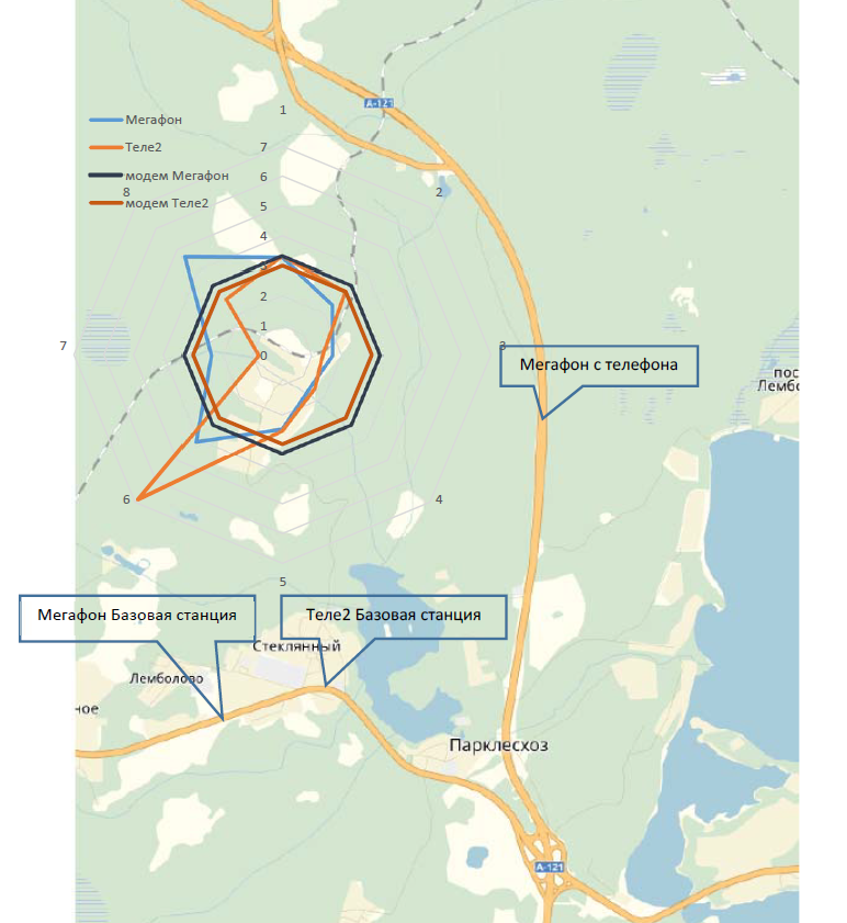
The positions of the nearest base stations (according to data from the Internet), as well as visible by the phone with MegaFon's SIM card (Network Cell Info application, showing the location of the current and several close BSs) are marked on the map. The lines “Megafon modem” and “Tele2 modem” show Internet speed without connecting an antenna, that is, using an omnidirectional antenna built into the modem. Such an antenna receives signals from all sides and sees not only the signal directly from the base station (or maybe not at all in direct line of sight), but also re-reflected signals from all directions. A directional antenna that has a gain in a certain direction will work more efficiently than an omnidirectional antenna, even if the signal is amplified with an amplifier, since noise will also be amplified.
 The lines "Megaphone" and "Tele2" demonstrate the speed of the Internet with an antenna connected to the modem. It is clearly seen that in certain directions the signal is significantly weaker, in others it has increased, which indicates the spatial selectivity of the smart antenna. Unfortunately, the Internet speed is not a radio characteristic, such as signal strength or signal-to-noise ratio, but the authors could not get at least some "service" information from the modem used. Probably, the software of other modems can give access to radio information, but not ours.
At the first stage, the interest of the authors is quite satisfied, in the future plans to add band-pass filters after antennas to reduce interference from out-of-band signals, to add a bidirectional low-noise amplifier with separation of receive and transmit frequencies.
On the Internet, there are many offers to sell external antennas for connecting to 4G modems. And although mobile operators do not recommend this, and even threaten to remove the modem from the guarantee, since the connectors on the modems are considered exclusively service, external antennas are sold very well. Several years ago, when the first Wimax modems from Yota, which were produced by Samsung, appeared, the coverage of that network was not very good even in the city. At the same time, the first external antennas of Chinese and one Russian manufacturer, Resonance, appeared on the market. The Wimax standard has now changed LTE, and all mobile operators sell portable modems. The market of external antennas has expanded significantly, you can find dozens of different types on the Internet. Some companies offer turnkey installation and creation of complete systems for country houses, using active amplifiers and additional antennas installed inside the house for local distribution of the signal. But for communication with the base station, in the overwhelming majority of cases, highly directional antennas are used, most often printed antenna arrays having a beam width of about 20 degrees both in azimuth and in elevation. The main problem of directional antennas is that they are manually sent once to a specific BS and, in the event of a signal loss from this BS, the connection is interrupted. The solution to this problem is smart antennas, which themselves are tuned to the base station without any human intervention. Most often they are used for installation on automobiles and other mobile objects (not in Russia) or for creating temporary communication channels where necessary and there are no other ways to quickly establish communication.
Smart antennas are of two types: adaptive and switching. An adaptive antenna is, in fact, an antenna array with the ability to instantly synthesize rays in arbitrary directions. The switched antenna has several antennas in different directions (usually in a circle), and, depending on which direction the signal is stronger, one or another antenna turns on, the remaining antenna antennas are inactive and wait for either a change in the subscriber’s position or switch to another base station, if the signal from for some reason became stronger. Thus, a smart antenna differs from known systems in that it adapts to changing reception conditions. Often the signal from different base stations may differ depending on the time of day or the time of year. And yet, thanks to this advantage, such an antenna can be used, for example, on hikes or in motor homes.
In order to test how such an antenna will work in real conditions, the team of authors has developed the simplest and cheapest smart antenna and conducted field tests.
It is known that the frequency range allocated for LTE is 200 MHz - 2.5 to 2.7 GHz. To clearly see this, an omnidirectional antenna was connected to the spectrum analyzer, the analyzer itself was switched to accumulation mode and left for a sufficiently long time. The results are shown in the graph above. In the same place, the subbands of various operators are plotted on the chart (information about the frequencies of the operators is found on the Internet). No further comments are required, except that the top Wi-Fi channels are also captured on the chart.
The proposed design is a drum of 8 faces and includes a microwave switch and control board. Each face is a separate antenna, which is a 4x1 printed grid. So that the rays do not overlap, but there are no “blind” zones, the azimuth width of the beam is 65 degrees and 19 degrees in elevation to achieve high gain (approximately 12 dBi). For ease of fabrication, a porous, but rather rigid insulation 5 mm thick was used as a substrate for microstrip patches. The dielectric constant of such a material is close to unity, and the insertion loss is negligible, which was tested on a specially made single patch. The strip lines, as well as the screens of the antennas, were cut out of copper foil deposited on thin lavsan, and glued with adhesive tape to the substrate. The antennas were designed for a frequency of 2.6 GHz, the CWS at the center frequency turned out to be close to 1, at the edges of the range it rose to 2, which is quite acceptable for antennas of communication devices.
Separately, an eight-channel switch was made, which connects the modem input to one of eight antennas aimed at the BS with the best signal. As controllable elements, pin-diodes from Infineon were used, and according to the authors, the control board should control them, which, receiving information from the modem, chooses which side is the best and that channel includes. Such a survey (verification of signals from all antennas) should occur several times per minute. Thus, when there is a change in the interference environment or signal strength from the BS, the smart antenna can choose a different direction. The photos below show a switch and a smart antenna with 2 strips removed.
Were conducted tests of smart antennas in the Leningrad region, where coverage of all operators is rather weak. Signals from two operators, MegaFon and Tele2, were checked. For testing, a Huawei E8372 modem was used, having “legitimate” connectors for connecting external antennas. Using speedtest.net, Internet speeds of both operators were measured without connecting an antenna, and then with an antenna and switching between all 8 sides. The results are shown in the picture below.
The positions of the nearest base stations (according to data from the Internet), as well as visible by the phone with MegaFon's SIM card (Network Cell Info application, showing the location of the current and several close BSs) are marked on the map. The lines “Megafon modem” and “Tele2 modem” show Internet speed without connecting an antenna, that is, using an omnidirectional antenna built into the modem. Such an antenna receives signals from all sides and sees not only the signal directly from the base station (or maybe not at all in direct line of sight), but also re-reflected signals from all directions. A directional antenna that has a gain in a certain direction will work more efficiently than an omnidirectional antenna, even if the signal is amplified with an amplifier, since noise will also be amplified.
The lines "Megaphone" and "Tele2" demonstrate the speed of the Internet with an antenna connected to the modem. It is clearly seen that in certain directions the signal is significantly weaker, in others it has increased, which indicates the spatial selectivity of the smart antenna. Unfortunately, the Internet speed is not a radio characteristic, such as signal strength or signal-to-noise ratio, but the authors could not get at least some "service" information from the modem used. Probably, the software of other modems can give access to radio information, but not ours.
At the first stage, the interest of the authors is quite satisfied, in the future plans to add band-pass filters after antennas to reduce interference from out-of-band signals, to add a bidirectional low-noise amplifier with separation of receive and transmit frequencies.
All Articles